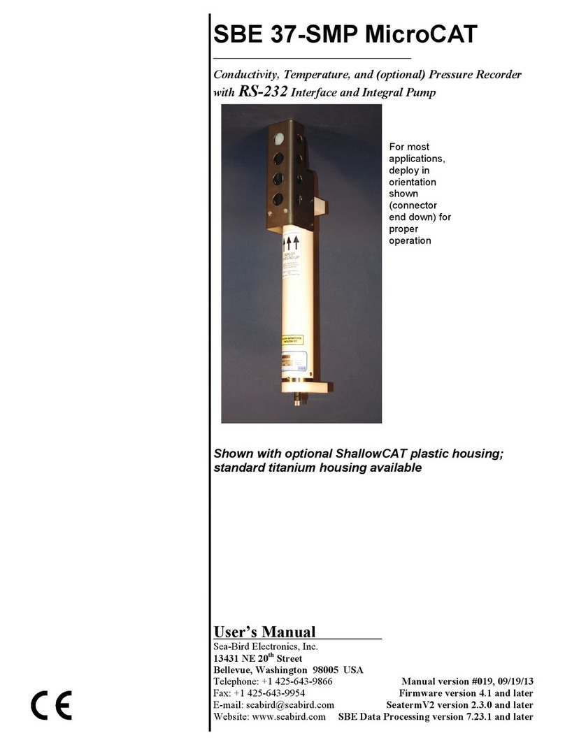
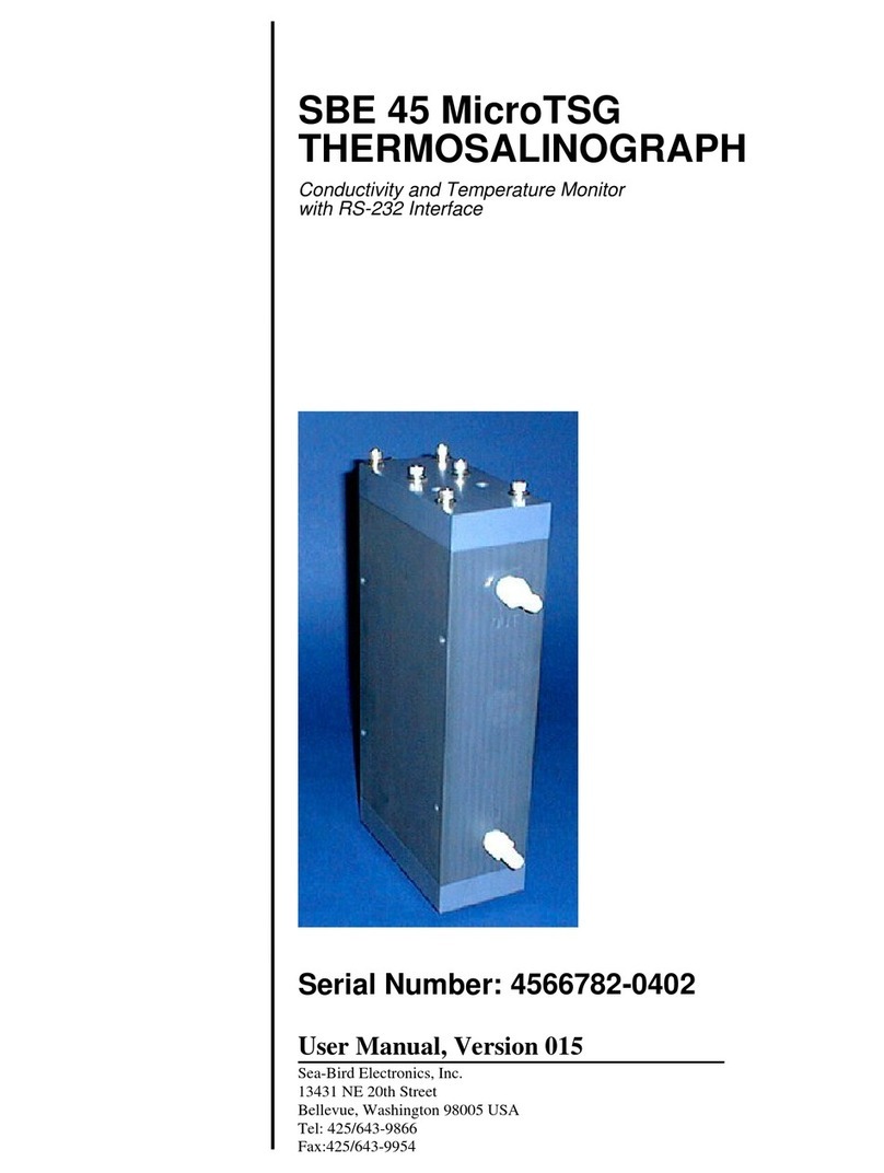
Sea-Bird Electronics SBE 19plusV2 User manual

Sea-Bird Electronics, Inc.
1808 136th Place NE
Bellevue, Washington 98005 USA
Tel: 425/643-9866
Fax:425/643-9954
SBE 19plusV2
SEACAT PROFILER
Conductivity, Temperature, and Pressure Recorder
with RS-232 Interface
Serial Number: 19P53231-6266
User Manual, Version 003

This page Intentionally Left Blank.

SEA-BIRD ELECTRONICS, INC.
1808 136th Place NE
Bellevue, Washington 98005 USA
Phone: (425) 643 9866
Fax: (425) 643 9954
Email: [email protected]
SBE 19plus CTD OPERATING AND REPAIR MANUAL
TABLE OF CONTENTS
Manual Generation Date....................................................................................................................................................................................................................................
1
Limited Liability Statement...............................................................................................................................................................................................................................
2
Warning...................................................................................................................................................................................................................................................
4
Configuration.............................................................................................................................................................................................................................................
5
Manual - Version 003......................................................................................................................................................................................................................................
8
Quick Reference Sheet - Version 003.......................................................................................................................................................................................................................
123
Ni-MH Battery Charger Manual - Version 002................................................................................................................................................................................................................
125
Specifications............................................................................................................................................................................................................................................
142
Calibrations..............................................................................................................................................................................................................................................
149
Pressure Test Certificates................................................................................................................................................................................................................................
156
Appnotes..................................................................................................................................................................................................................................................
160
Drawings..................................................................................................................................................................................................................................................
251
Warranty..................................................................................................................................................................................................................................................
262
Service Request Form......................................................................................................................................................................................................................................
264

Manual Generation Date: 11 February 2009
1

L I M I T E D L I A B I L I T Y S T A T E M E N T
Extreme care should be exercised when using or servicing this equipment. It should be used or
serviced only by personnel with knowledge of and training in the use and maintenance of
oceanographic electronic equipment.
SEA-BIRD ELECTRONICS, INC. disclaims all product liability risks arising from the use or servicing of
this system. SEA-BIRD ELECTRONICS, INC. has no way of controlling the use of this equipment or of
choosing the personnel to operate it, and therefore cannot take steps to comply with laws pertaining to
product liability, including laws which impose a duty to warn the user of any dangers involved in
operating this equipment. Therefore, acceptance of this system by the customer shall be conclusively
deemed to include a covenant by the customer to defend, indemnify, and hold SEA-BIRD
ELECTRONICS, INC. harmless from all product liability claims arising from the use of servicing of this
system.
2

This page intentionally left blank.
3

WARNING !!
Do not submerge this instrument (S/N 19P53231-6266)
beyond the depth rating of the lowest rated component listed below!
Main Housing (Plastic) 600 meters
Pressure Sensor (350 dBar) Druck 350 meters
DO Sensor (SBE 43) 600 meters
Pump (SBE 5P) 600 meters
Seapoint Turbidity Meter 6000 meters
Fluorometer (WETLabs - ECO-FLRT) 600 meters
4

SYSTEM CONFIGURATION 11 February 2009
Model SBE 19plusV2 S/N 19P53231-6266
Instrument Type SBE 19plusV2 SeaCaT Profiler
Firmware Version 2.1
Communications 4800 baud, 8 data bits, no parity, one stop bit
Memory 64MB
Housing 600 meter (Acetron Plastic)
0 Conductivity Raw Frequency 2534.35 Hz
Pressure Sensor Strain Gauge: 350 dBar, S/N 2863051
Computer communications (Data I/O) connector Located on the P/N 17709 Y-Cable
Number of Voltages Sampled: 3
Serial RS-232C Sensor None
Data Format:
Count Temperature
Frequency Conductivity
Count Pressure, Strain Gauge
Stored Voltage 0 (External Voltage 0) Oxygen, SBE 43
Stored Voltage 1 (External Voltage 2) OBS, Seapoint Turbidity
Stored Voltage 2 (External Voltage 4) Fluorometer, WETLAB ECO-AFL/FL
Pump (SBE 5P) 055194
DO Sensor (SBE 43) 431571
Seapoint Turbidity Meter 11826
Fluorometer (WETLabs - ECO-FLRT) FLRT-1299
Individual Voltage Delay Settings for Moored Mode Applications:
SBE 43 30 Seconds
Additional Sensor(s) 4 Seconds
Configured Overall Voltage Delay Setting: 30 Seconds
Note: The 30 second voltage delay for the SBE 43 is based on the typical response time at 2 degrees Celsius for
a 0.5-mil thick membrane to read within 1% of its final value. Please consult Application Note 64 under Summary
of Response Times for Moored Applications for more information.
Note: Overall Voltage Delay Setting is based on the longest time delay listed above. To recalculate this value
when adding or removing sensors, please refer to manual text.
5

IMPORTANT SOFTWARE & HARDWARE CONFIGURATION INFORMATION
Sea-Bird supplies two versions of our software package for communication, real-time data acquisition, and data
analysis and display:
•SEASOFT-Win32 - Windows software for PC running Win 95/98/NT/2000/XP
•SEASOFT-DOS - DOS software for IBM-PC/AT/386/486 or compatible computer with a hard drive
Detailed information on the use of the Windows software follows:
SEASOFT-Win32
SEASOFT-Win32 software was supplied on a CD-ROM with your CTD. This software package is designed to run on a PC running Win
95/98/NT/2000/XP. The CD-ROM also contains software manuals that describe the appropriate applications for the various programs, the
procedure for installing the software, and instructions on using the programs. There are three primary programs used with the CTD for
setup, data collection and retrieval, data display, and data processing:
•SEATERM - terminal program for setup of the CTD and uploading of data from the CTD memory (Note: If using the CTD with the
90208 Auto Fire Module or SBE 17plus V2 SEARAM, use SeatermAF instead of SEATERM)
•SEASAVE - real-time data acquisition program
•SBE Data Processing - data processing program
Instructions for using the software are found in their Help files.
To communicate with the CTD to set it up or to upload data from the CTD memory to the computer hard drive,
SEATERM must have information about the CTD hardware configuration (communication parameters, internal
firmware, etc.) and about the computer. To communicate with the CTD, double click on Seaterm.exe:
1. In the Configure menu, select the CTD. The Configuration Options dialog box appears.
A. On the COM Settings tab, select the firmware version (if applicable), baud rate, data bits, and parity to match the CTD’s
configuration sheet. If necessary, change the com port to match the computer you are using.
B. On the Upload Settings tab, enter upload type (all as a single file, etc.) as desired.
For the SBE 17 and 25 only: enter the serial number for the SBE 3 (temperature) and SBE 4 (conductivity) modular sensors,
exactly as they appear in the configuration (.con) file.
C. On the Header Information tab, change the settings as desired.
Click OK when done. SEATERM saves the settings in a SEATERM.ini file.
2. On the Toolbar, click Connect to communicate with the CTD.
3. To set up the CTD prior to deployment:
On the Toolbar, click Status. SEATERM sends the Status command and displays the response. Verify that the
CTD setup matches your desired deployment. If not, send commands to modify the setup.
4. To upload data from the CTD:
On the Toolbar, click Upload to upload data from the CTD memory to the computer.
Sea-Bird CTDs store and/or transmit data from their primary and auxiliary sensors in the form of binary or
hexadecimal number equivalents of the sensors’ frequency or voltage outputs. This is referred to as the raw data.
The calculations required to convert from raw data to engineering units of the measured parameters (temperature,
conductivity, pressure, dissolved oxygen, pH, etc.) are performed using the software, either in real time, or after
the data has been stored in a file. SEASAVE creates the file in real time. As noted above, SEATERM uploads the
recorded data and creates the file on the computer hard drive.
To successfully store data to a file on the computer and subsequently convert it to engineering units, the software
must know the CTD type, CTD configuration, and calibration coefficients for the sensors installed on the CTD.
This information is unique to each CTD, and is contained in a configuration file. The configuration file, which has
a .con extension, was written onto a floppy disk and the CD-ROM shipped with the CTD. The .con file for a given
CTD is named with the last four digits of the serial number for that CTD (e.g., 1234.con). The configuration file is
created or modified (e.g., changing coefficients after recalibration, or adding another sensor) by using the
Configure menu in SEASAVE or
SBE Data Processing. The configuration file is used by SEASAVE to convert raw data to engineering units
when it acquires, stores, and displays real-time data. The configuration file is also used by some modules in
SBE Data Processing (Data Conversion and Derive) that convert raw data to engineering units during data
processing.
6

The instrument type and instrument configuration settings of the .con file and the required setup for the
SEATERM.ini file for the CTD as delivered are documented below. The calibration coefficients for the CTD's
sensors are contained in the calibration coefficient section of the CTD manual.
NOTE:
SEATERM will not upload data correctly without a properly configured SEATERM.ini file. SEASAVE and SBE
Data Processing will not interpret the data correctly without the correct .con file.
SEASOFT CONFIGURATION:
The correct instrument type for your instrument is SBE 19plus V2 SEACAT Profiler. The correct settings for the configuration of
your instrument as delivered are documented below:
Strain Gauge
3
None
3. Count Pressure, Strain Gauge
4. A/D Voltage 0 Oxygen, SBE 43
5. A/D Voltage 1 OBS, Seapoint Turbidity
6. A/D Voltage 2 Fluorometer, WETLAB ECO-AFL/FL
7

SBE 19plus V2
SEACAT Profiler
Conductivity, Temperature, and Pressure Recorder
with RS-232 Interface
User’s Manual
Sea-Bird Electronics, Inc.
1808 136th Place NE
Bellevue, Washington 98005 USA Manual Version #003, 11/03/08
Telephone: 425/643-9866 Firmware Version 2.1 and later
Fax: 425/643-9954 SeatermV2 Version 1.00d and later
E-mail: seabir[email protected] Seasave V7 Version 7.18b and later
Website: www.seabird.com SBE Data Processing Version 7.18b and later
8

2
Limited Liability Statement
Extreme care should be exercised when using or servicing this equipment. It should be used or serviced
only by personnel with knowledge of and training in the use and maintenance of oceanographic
electronic equipment.
SEA-BIRD ELECTRONICS, INC. disclaims all product liability risks arising from the use or servicing
of this system. SEA-BIRD ELECTRONICS, INC. has no way of controlling the use of this equipment
or of choosing the personnel to operate it, and therefore cannot take steps to comply with laws
pertaining to product liability, including laws which impose a duty to warn the user of any dangers
involved in operating this equipment. Therefore, acceptance of this system by the customer shall be
conclusively deemed to include a covenant by the customer to defend, indemnify, and hold SEA-BIRD
ELECTRONICS, INC. harmless from all product liability claims arising from the use or servicing of
this system.
9

Table of Contents
3
Table of Contents
Section 1: Introduction ........................................................................ 5
About this Manual .............................................................................................5
How to Contact Sea-Bird ...................................................................................5
Quick Start .........................................................................................................5
Unpacking SBE 19plus V2 ................................................................................6
Section 2: Description of SBE 19plus V2 ........................................... 7
System Description ............................................................................................7
Specifications...................................................................................................11
Dimensions and End Cap Connectors..............................................................13
Batteries ...........................................................................................................14
Battery Endurance............................................................................................14
External Power.................................................................................................16
Data Storage.....................................................................................................18
Data I/O ...........................................................................................................18
Magnetic Reed Switch .....................................................................................18
Configuration Options and Plumbing ..............................................................19
Vertical Mount..........................................................................................19
Horizontal Mount......................................................................................22
Section 3: Power and Communications Test ................................... 23
Software Installation ........................................................................................23
Test Setup ........................................................................................................23
Test ..................................................................................................................24
Section 4: Deploying and Operating SBE 19plus V2 ...................... 27
Sampling Modes ..............................................................................................27
Profiling Mode..........................................................................................28
Moored Mode ...........................................................................................29
Pump Operation - General ...............................................................................30
Pump Operation - Profiling Mode ...................................................................30
Pump Operation - Moored Mode.....................................................................31
Moored Mode Pump Setting Recommendations ......................................32
Real-Time Setup ..............................................................................................33
Baud Rate and Cable Length ....................................................................33
Real-Time Data Acquisition .....................................................................34
Timeout Description ........................................................................................34
Command Descriptions....................................................................................35
Data Output Formats........................................................................................60
Optimizing Data Quality for Profiling Applications........................................67
Installing Anti-Foul Fittings for Moored Applications ....................................69
Setup for Deployment ......................................................................................71
Deployment......................................................................................................72
Acquiring Real-Time Data with SEASAVE....................................................73
Verifying Contents of .con File ................................................................73
Acquiring Real-Time Data........................................................................75
Recovery ..........................................................................................................77
Physical Handling.....................................................................................77
Uploading Data.........................................................................................78
Processing Data Using SBE Data Processing ..................................................82
Verifying Contents of Configuration (.con) File ......................................82
Editing Raw Data File......................................................................................84
10

Table of Contents
4
Section 5: Routine Maintenance and Calibration........................... 85
Corrosion Precautions......................................................................................85
Connector Mating and Maintenance ................................................................85
Plumbing Maintenance ....................................................................................86
Replacing / Recharging Batteries.....................................................................87
Conductivity Cell Maintenance .......................................................................91
Pressure Sensor Maintenance ..........................................................................92
Pump Maintenance ..........................................................................................92
Replacing Anti-Foulant Devices (SBE 16plus, SBE 19plus)...........................93
Sensor Calibration............................................................................................94
Section 6: Troubleshooting................................................................ 96
Problem 1: Unable to Communicate................................................................96
Problem 2: No Data Recorded .........................................................................96
Problem 3: Nonsense or Unreasonable Data....................................................97
Problem 4: Program Corrupted........................................................................97
Glossary .............................................................................................. 98
Appendix I: Functional Description and Circuitry....................... 100
Sensors...........................................................................................................100
Sensor Interface .............................................................................................100
Real-Time Clock............................................................................................100
Battery Wiring ...............................................................................................101
Appendix II: Electronics Disassembly/Reassembly ...................... 102
Appendix III: Command Summary ............................................... 103
Appendix IV: AF24173 Anti-Foulant Device ................................ 107
Appendix V: Replacement Parts .................................................... 111
Index.................................................................................................. 114
11

Section 1: Introduction
5
Section 1: Introduction
This section includes contact information, Quick Start procedure, and photos
of a standard SBE 19plus V2 shipment.
About this Manual
This manual is to be used with the SBE 19plus V2 SEACAT Profiler
Conductivity, Temperature, and Pressure Recorder.
It is organized to guide the user from installation through operation and data
collection. We have included detailed specifications, command descriptions,
maintenance and calibration information, and helpful notes throughout
the manual.
Sea-Bird welcomes suggestions for new features and enhancements of our
products and/or documentation. Please e-mail any comments or suggestions to
How to Contact Sea-Bird
Sea-Bird Electronics, Inc.
1808 136th Place Northeast
Bellevue, Washington 98005 USA
Telephone: 425-643-9866 Fax: 425-643-9954
Business hours:
Monday-Friday, 0800 to 1700 Pacific Standard Time
(1600 to 0100 Universal Time)
Except from April to October, when we are on summer time
(1500 to 0000 Universal Time)
Quick Start
Follow these steps to get a Quick Start using the SBE 19plus V2.
The manual provides step-by-step details for performing each task:
1. Install batteries and test power and communications (see Section 3: Power
and Communications Test).
2. Deploy the 19plus V2 (see Section 4: Deploying and Operating
SBE 19plus V2):
A. Install new batteries if necessary.
B. Ensure all data has been uploaded, and then send InitLogging to
make entire memory available for recording if desired.
C. Set date and time and establish setup and logging parameters.
D. Moored mode - Set 19plus V2 to start logging now or in the future.
E. Install dummy plugs and/or cable connectors, and locking sleeves.
F. If applicable, remove Tygon tubing that was looped end-to-end
around conductivity cell for storage. Reconnect tubing from pump to
conductivity cell.
G. Profiling mode - Put magnetic switch in On position, send
commands to start logging now or in the future, or apply external
power, as appropriate for your instrument’s setup.
H. Deploy 19plus V2.
12

Section 1: Introduction
6
Unpacking SBE 19plus V2
Shown below is a typical SBE 19plus V2 shipment.
Spare o-ring and
hardware kit
Conductivity cell cleaning
solution (Triton-X) Conductivity cell filling
and storage kit
Software, and Electronic Copies of
Software Manuals and User Manual
2-pin dummy plug
and locking sleeve
25-pin to 9-pin adapter
(for use with computer
with DB-25 connector)
I/O Cable
SBE 19plus V2 SEACAT with SBE 5M plastic pump
SBE 19plus V2 Manual
SBE 19plus V2
SEACAT
13

Section 2: Description of SBE 19plus V2
7
Section 2: Description of SBE 19plus V2
This section describes the functions and features of the SBE 19plus V2
SEACAT Profiler, including system description and auxiliary equipment,
specifications, dimensions and end cap connectors, batteries and battery
endurance, external power and cable length limitations, data storage,
communication settings, magnetic reed switch, and configuration options
and plumbing.
System Description
The SBE 19plus V2 SEACAT Profiler is designed to measure conductivity,
temperature, and pressure in marine or fresh-water environments at depths up
to 7000 meters (22,900 feet). The 19plus V2 operates in two modes:
•Profiling mode for acquiring vertical profiles. The 19plus V2 runs
continuously, sampling at 4 scans per second (4 Hz). It can average up to
32,767 samples, storing and transmitting only averaged data.
•Moored mode for acquiring time series measurements once every
10 seconds to every 4 hours, adjustable in 1-second increments. Between
samples, the 19plus V2 powers down, drawing only 20 microamps.
Self-powered and self-contained, the 19plus V2 features the proven Sea-Bird
conductivity and temperature sensors and a precision, semiconductor, strain-
gauge pressure sensor. Nine D-size alkaline batteries provide 60 hours
operation in Profiling mode; the 64 Mbyte FLASH RAM records 400 hours of
conductivity, temperature, and pressure data while sampling at four scans per
second (other configurations/setups vary). The 19plus V2 three-wire RS-232C
interface provides simultaneous, real-time monitoring. User-selectable output
format is raw data or engineering units, in hexadecimal or decimal form; XML
output is also available. Setup, diagnostics, and data extraction are performed
without opening the housing. The 19plus V2 can power and acquire the
outputs of external sensors.
Logging is started by sliding the On/Off switch, by command via the RS-232
interface, or by applying external power, depending on your instrument setup.
A standard 19plus V2 is supplied with:
•Plastic housing for depths to 600 meters (1950 feet)
•64 Mbyte FLASH RAM memory
•Internally mounted strain-gauge pressure sensor
•9 D-size alkaline batteries (Duracell MN1300, LR20)
•Impulse glass-reinforced epoxy bulkhead connectors:
- one 6-pin connector for data I/O, external power, and pump power;
- three 6-pin connectors, for two differential auxiliary A/D inputs each;
- one 4-pin connector, for RS-232 auxiliary sensor (SBE 38 secondary
temperature sensor, or up to two Pro-Oceanus Gas Tension Devices)
•T-C Duct, which ensures that Temperature and Conductivity
measurements are made on the same parcel of water
•SBE 5M miniature pump (with plastic housing for depths to 600 meters)
for pumped conductivity; by fixing the flow to a constant rate, the pump
ensures a constant conductivity time response. The T-C duct and pump
combination results in dramatically lower salinity spiking.
14

Section 2: Description of SBE 19plus V2
8
SBE 19plus V2 options / accessories include:
•Titanium housing for use to 7000 meters (22,900 feet)
•Internally mounted Quartz pressure sensor in place of strain-gauge sensor
•SBE 5M miniature pump with titanium housing in place of plastic housing
•SBE 5P (plastic) or 5T (titanium) pump in place of SBE 5M for use with
dissolved oxygen and/or other pumped auxiliary sensors
•Sensors for dissolved oxygen, pH (Profiling mode only), fluorescence,
light (PAR), light transmission, and turbidity
•Stainless steel cage
•Wet-pluggable (MCBH) connectors in place of standard connectors
•Nickel Metal Hydride (NiMH) batteries and charger
•Nickel Cadmium (Ni-Cad) batteries and charger
•Moored mode conversion kit with anti-foulant device fittings, for when
19plus V2 used on moorings
Future upgrades and enhancements to the SBE 19plus V2 firmware can be
easily installed in the field through a computer serial port and the Data I/O,
Pump, and External Power bulkhead connector on the 19plus V2, without the
need to return the 19plus V2 to Sea-Bird.
The 19plus V2 can be used with the following Sea-Bird equipment:
•SBE 32 Carousel Water Sampler and SBE 33 Carousel Deck Unit OR
SBE 55 ECO Water Sampler and SBE 33 Carousel Deck Unit -
The SBE 32 or SBE 55 provides +15 VDC power to the 19plus V2 and
has ample power for auxiliary sensors not normally supported by battery-
powered CTDs. CTD data from the 19plus V2 is converted into single-
wire telemetry for transmission over long (10,000 meter [32,800 feet]) sea
cables. Bottles may be closed at any depth without interrupting CTD data
via software control using the SEASAVE program or from the front panel
of the SBE 33 Deck Unit. See the SBE 33 manual for operating details.
Notes:
•The SBE 32 Carousel is a 12-,
24-, or 36-bottle water sampler. The
SBE 55 ECO is a 3- or 6-bottle
water sampler.
•SEASAVE 7.18 or later also
supports acquisition of data from a
NMEA device connected directly
to the computer (instead of the
deck unit
)
.
SBE 32 Real-Time Operation
SBE 55 Real-Time Operation
15

Section 2: Description of SBE 19plus V2
9
•SBE 36 CTD Deck Unit and Power Data Interface Module (PDIM) -
These items provide power and real-time data handling capability over
single-conductor sea cables using the same method employed in the
SBE 32/SBE 33. The PDIM is a small pressure housing that is mounted on
or near the 19plus V2. It provides +15 VDC power to the 19plus V2 and
interfaces two-way RS-232 communications from the 19plus V2 to the
telemetry used on the sea cable. See the SBE 36/PDIM manual for
operating details.
•SBE 32 Carousel Water Sampler and Auto Fire Module (AFM) - The
AFM, mounted on or near the 19plus V2, allows the SBE 32 to operate
autonomously on non-conducting cables. The AFM supplies the power,
logic, and control commands to operate the SBE 32. The AFM monitors the
pressure data recorded by the 19plus V2 in real-time, closing water sampler
bottles at predefined pressures (depths) or whenever the system is stationary
for a specified period of time. Bottle number, firing confirmation, and five
scans of CTD data are recorded in the AFM memory for each bottle fired.
See the AFM manual for operating details.
SBE 32 Autonomous Operation
Note:
SEASAVE 7.18 or later also supports
acquisition of data from a NMEA
device connected directly to the
computer (instead of the deck unit).
16

Section 2: Description of SBE 19plus V2
10
•SBE 55 ECO Water Sampler - The SBE 55 has built-in capabilities
similar to that of an SBE 32 Carousel Water Sampler integrated with an
Auto Fire Module, allowing the SBE 55 to operate autonomously on non-
conducting cables. The SBE 55 monitors the pressure data recorded by the
19plus V2 in real-time, closing water sampler bottles at predefined
pressures (depths) or whenever the system is stationary for a specified
period of time. Bottle number, firing confirmation, and five scans of CTD
data are recorded in the SBE 55 memory for each bottle fired. See the
SBE 55 manual for operating details.
The SBE 19plus V2 is supplied with a powerful Win 2000/XP software
package, SEASOFT-Win32, which includes:
•SeatermV2 – terminal program for easy communication and data
retrieval. SeatermV2 is a launcher. Depending on the instrument selected
it launches Seaterm232 (RS-232 instruments, such as the 19plus V2),
Seaterm485 (RS-485 instruments), or SeatermIM (inductive modem
instruments).
•SEASAVE V7 – program for acquiring, converting, and displaying real-
time or archived raw data.
•SBE Data Processing – program for calculation and plotting of
conductivity, temperature, pressure, auxiliary sensor data, and derived
variables such as salinity and sound velocity.
Note:
The SBE 32 Carousel is a 12-, 24-, or
36-bottle water sampler. The SBE 55
ECO is a 3- or 6-bottle water sampler.
Notes:
•Help files provide detailed
information on the use of
SeatermV2, SEASAVE V7, and
SBE Data Processing.
•Separate software manuals on the
CD-ROM also provide information
on the use of SEASAVE V7 and
SBE Data Processing.
•Sea-Bird also supplies an older
version of SEASAVE, SEASAVE-
Win32. However, all SEASAVE
instructions in this manual are
written for SEASAVE V7. See
SEASAVE-Win32’s manual and/or
Help files if you prefer to use the
older software.
•Sea-Bird supplies the current
version of our software when you
purchase an instrument. As software
revisions occur, we post the revised
software on our FTP site. See our
website (www.seabird.com) for the
latest software version number, a
description of the software changes,
and instructions for downloading the
software from the FTP site.
17
Table of contents
Other Sea-Bird Electronics Measuring Instrument manuals
