Sea-Bird Electronics SEACAT SBE 19 User manual

SEACAT SBE 19
CONDUCTIVITY, TEMPERATURE, DEPTH RECORDER
OPERATING MANUAL
SEA-BIRD ELECTRONICS, INC.
1808 136th Place NE
Bellevue, Washington 98005 USA
Phone: (425) 643 9866 Fax: (425) 643-9954 Telex: 292915 SBEI
email: seabird@seabird.com
vers. 19.19

L I M I T E D L I A B I L I T Y S T A T E M E N T
Extreme care should be exercised when using or servicing this equipment. It should be used or
serviced only by personnel with knowledge of and training in the use and maintenance of
oceanographic electronic equipment.
SEA-BIRD ELECTRONICS, INC. disclaims all product liability risks arising from the use or servicing of
this system. SEA-BIRD ELECTRONICS, INC. has no way of controlling the use of this equipment or of
choosing the personnel to operate it, and therefore cannot take steps to comply with laws pertaining to
product liability, including laws which impose a duty to warn the user of any dangers involved in
operating this equipment. Therefore, acceptance of this system by the customer shall be conclusively
deemed to include a covenant by the customer to defend, indemnify, and hold SEA-BIRD
ELECTRONICS, INC. harmless from all product liability claims arising from the use of servicing of this
system.

SBE 19 SEACAT PROFILER
TABLE OF CONTENTS
1-1 INTRODUCTION.......................................................................................................... 1
1-2 FUNCTIONAL DESCRIPTION......................................................................................... 2
1-2.1 SENSORS............................................................................................................ 2
1-2.2 SENSOR INTERFACE............................................................................................. 2
1-2.3 REAL-TIME CLOCK ............................................................................................... 2
1-2.4 MEMORY............................................................................................................. 3
1-2.5 MAGNETIC REED SWITCH..................................................................................... 3
1-2.6 DATA I/O ............................................................................................................ 4
1-2.7 BATTERIES.......................................................................................................... 4
1-2.8 HOUSING AND MECHANICAL DESIGN.................................................................... 4
1-3 SPECIFICATIONS ........................................................................................................ 5
2-1 CONFIGURATION OPTIONS.......................................................................................... 6
2-2 SEACAT PROFILER COMMUNICATION FUNDAMENTALS ................................................ 7
2-2.1 COMMAND FORMAT............................................................................................ 8
2-2.2 EDITING .............................................................................................................. 9
2-2.3 COMMAND SUMMARY......................................................................................... 9
2-2.4 DIAGNOSTICS .................................................................................................... 10
2-2.5 STATUS............................................................................................................. 11
2-2.6 SETUP................................................................................................................ 12
2-2.7 LOGGING ........................................................................................................... 16
2-2.8 STOP LOGGING................................................................................................... 17
2-2.9 DATA RETRIEVAL ............................................................................................... 17
2-3 DATA FORMAT ......................................................................................................... 18
2-3.1 PROFILING MODE................................................................................................ 19
2-3.1.1 PAINE STRAIN GAUGE PRESSURE................................................................... 19
2-3.1.2 PAROSCIENTIFIC DIGIQUARTZ PRESSURE SENSOR.......................................... 22
2-3.2 MOORED MODE.................................................................................................. 23
2-4 SEASOFTSOFTWARE CONFIGURATION FILES........................................................... 23
2-5 OPERATION USING TERM19....................................................................................... 24
2-5.1 TERMINAL SET UP FORM..................................................................................... 25
2-5.2 DATA UPLOAD SETUP FORM............................................................................... 27
2-5.3 TERMINAL PROGRAM: FIELD OPERATION.............................................................. 29
2-6 DATA RECORDING AND READOUT: SAMPLE SESSIONS ............................................... 29
2-6.1 SAMPLE SESSION - PROFILING MODE................................................................... 30
2-6.1.1 RECORD DATA WITH SEACAT PROFILER (COMPUTER INITIATED) ..................... 30
2-6.1.2 RECORD DATA WITH SEACAT PROFILER (MAGNETIC SWITCH INITIATED) ......... 30
2-6.1.3 RETRIEVE DATA FROM SEACAT PROFILER...................................................... 31
2-6.1.4 DISPLAY SEACAT PROFILER DATA USING SEASOFT........................................ 32

3-1 INSTALLATION AND OPERATING INSTRUCTIONS......................................................... 32
3-1.1 BATTERY INSTALLATION..................................................................................... 33
3-1.2 PUMP OPERATION .............................................................................................. 33
3-1.3 DEPLOYMENT..................................................................................................... 34
3-1.4 OPTIMIZING DATA QUALITY................................................................................ 34
3-1.5 RECOVERY......................................................................................................... 35
3-1.6 STORAGE........................................................................................................... 36
4-1 COMMON PROBLEMS AND THEIR CURES .................................................................... 36
4-1.1 UNABLE TO COMMUNICATE WITH PROFILER........................................................ 36
4-1.2 NO DATA RECORDED.......................................................................................... 37
4-1.3 NONSENSE DATA ............................................................................................... 37
4-1.4 RESETTING THE SBE 19's INTERNAL MEMORY...................................................... 37
5-1 ROUTINE MAINTENANCE AND CALIBRATION............................................................... 38
5-1.1 CORROSION PRECAUTIONS................................................................................. 38
5-1.2 CONDUCTIVITY CELL STORAGE........................................................................... 38
5-1.3 SENSOR CALIBRATION........................................................................................ 38
6-1 DESCRIPTION OF SEACAT PROFILER CIRCUITRY.......................................................... 40
6-1.1 BATTERY WIRING AND POWER SUPPLY................................................................ 40
6-1.2 SENSOR MULTIPLEXING ...................................................................................... 40
6-1.3 WEIN-BRIDGE OSCILLATOR.................................................................................. 41
6-1.4 SQUARING CIRCUITS AND AP COUNTER .............................................................. 41
6-1.5 A/D CONVERTER (INTERNAL DIAGNOSTICS) ....................................................... 41
6-1.6 CPU AND DATA I/O............................................................................................. 41
6-1.7 REAL-TIME CLOCK .............................................................................................. 42
6-1.8 MEMORY............................................................................................................ 42
7-1 DISASSEMBLY/REASSEMBLY INSTRUCTIONS............................................................... 42
7-2 O-RING SIZES............................................................................................................ 43
ver 19.19 This manual is intended to be used with SBE 19 SEACAT PROFILERS with firmware versions
3.1b and above or versions 4.0b and above.

1
1-1 INTRODUCTION
The SBE 19 SEACAT Profiler is designed to measure electrical conductivity, temperature, and pressure in
marine or fresh water environments to depths up to 10,500 meters. The standard SEACAT Profiler will
operate in two modes, profiling and moored. Profiling mode is designed for applications where vertical
profiles of the measured parameters are required. In profiling mode, the sample rate can be varied from
twice a second to once every 4 minutes in half-second increments. Moored mode provides a means of
acquiring time series measurements at sample rates of once every 15 seconds to once every 8 hours,
adjustable in one-second increments.
Self-powered (9 D-size alkaline batteries provide 26 hours operation in profiling mode) and self-contained,
the SBE 19 features the proven Sea-Bird conductivity and temperature sensors and a precision
semiconductor strain-gauge pressure transducer. The 1024K byte CMOS static RAM will record 24 hours
of conductivity, temperature, and pressure data while sampling at two scans per second (48, 96, or 192
hours with optional 2, 4, or 8 megabyte memories). Set-up, check-out, and data extraction are performed
without opening the housing. Simultaneous real time monitoring is possible using the SEACAT Profiler's
two wire RS-232C transmit capability. Sea-Bird's powerful SEASOFT CTD software derives salinity,
density, sound velocity, and other ocean parameters from stored CTD values and may be used for data
analysis, plotting, and archiving. External sensors may be powered and their frequency or voltage outputs
acquired by the SBE 19.
Standard SEACAT Profilers are supplied with 1024K byte memory, 600 meter capability plastic housings,
SBE 5M submersible pump for pumped conductivity, a second bulkhead connector wired for 4 single
ended auxiliary A/D inputs, and alkaline batteries.
SEACAT Profiler options include:
•aluminum or titanium housings for use to 3400, 6800, or 10500 meters
•2, 4, or 8 megabyte memories
•internal optical isolation and cable drivers for real time telemetry over cables up to 7000 meters long
•2 differential input, 4 auxiliary A/D channels
•sensors for dissolved oxygen, pH, fluorescence, light (PAR), light transmission, and turbidity
•SBE 5T submersible pump for use with dissolved oxygen and/or pumped fluorometer sensors
The SEACAT Profiler can be used with the SBE 32 Carousel Water Sampler and the SBE 33 Carousel Deck
Unit. The SBE 32 Carousel provides +15 VDC power to the SBE 19 and has ample power available for
auxiliary sensors not normally supported by battery-powered CTDs. The CTD data from the SEACAT
Profiler is converted into single wire telemetry for transmission over long (10,000 meter) seacables.
Bottles may be closed at any depth without interrupting CTD data via software control using the
SEASAVE program or from the front panel of the SBE 33 Deck Unit.
Also available for use with the SEACAT Profiler is the SBE 36 CTD Deck Unit and PN 90227 Power Data
Interface Module (PDIM). These items provide real time power and data handling capabilities over single
conductor seacables using the same method as employed in the SBE 32/SBE 33 Carousel Water Sampler.
The PDIM is a small pressure housing that is mounted on or near the CTD. It provides +15 VDC power to
the SEACAT Profiler and interfaces two way RS232 communications from the SEACAT Profiler to the
telemetry used on the seacable.

2
1-2 FUNCTIONAL DESCRIPTION
1-2.1 SENSORS
SEACAT embodies the sensor elements (Pyrex cell and pressure-protected thermistor) and Wein-bridge
oscillator interface technique previously employed in Sea-Bird's modular SBE 3 and SBE 4 sensors, but
differs in using multiplexing to allow a single oscillator to service both temperature and conductivity
measurements.
The pressure sensor is either a Paine strain-gauge sensor or a Paroscientific Digiquartz pressure sensor.
1-2.2 SENSOR INTERFACE
Temperature or conductivity dependent variable frequencies generated by the Wein-bridge are acquired
(digitized) using a hybrid period counting technique (AP Counter) like that used in the Sea-Bird SBE 9 CTD.
The AP Counter determines integer and fractional cycles of the variable frequency during a fixed time
interval of 0.125 seconds (this period, and therefore the count accuracy, is determined using a precision
quartz TCXO). The resulting count is offset and scaled in preparation for storage in CMOS static RAM.
Drift associated with changes in ambient temperature or component aging is compensated in SEACAT by
switching stable resistors (Vishay types) into the Wein-bridge oscillator once per minute. The resulting
frequencies (representing the approximate upper and lower frequency limits of the oscillator) are measured
and used to correct circuit drift. Consequently, the accuracy of SEACAT electronics is limited principally
by the stability of the Vishay resistors and time-base quartz crystal.
The strain gauge pressure sensor is operated as a DC bridge. The amplified sensor output signal is acquired
by a 12-bit plus sign A/D converter providing an effective resolution of 0.015%.
1-2.3 REAL-TIME CLOCK
To minimize battery current drain, a low power 'watch' crystal is used as the real-time-clock frequency
source. Initial error, ambient temperature-induced drift, and aging of the 'watch' crystal is compensated by
measuring its actual frequency against the TCXO each time SEACAT Profiler powers up. The measured
discrepancy (if any) is used to arithmetically correct the low power clock.
Clock power is supplied by the main battery or the internal lithium back-up, depending on which voltage is
higher. Even a 'dead' main battery will usually supply the very small clock power drain (less than
60 microamperes), so the back-up cells will last indefinitely.

3
1-2.4 MEMORY
Memory consists of eight low standby-power CMOS static 128K X 8 RAM chips. Each recorded CTD scan
contains 6 bytes of data (standard units), and 4000 bytes are reserved for scratch-pad use, including
storage of header information containing cast number (up to 150 casts), time/date, and beginning and
ending sample number for the cast. SEACAT Profiler sample capacity may be predicted by use of the
following relationships:
M = memory size 1,048,576 bytes (1024K memory)
Z = scratch-pad reserved area, approximately 4000 bytes
B = bytes per scan (6 in a standard system)
S = # scans recorded (samples) = (M - Z) / B
For the standard 1024K version, the memory can hold approximately 174,000 samples of C, T, and P.
Either the lithium back-up or the main battery (whichever has the higher voltage) will keep the memory
intact. The main battery may be replaced without disturbing the memory contents.
1-2.5 MAGNETIC REED SWITCH
A magnetic switch is mounted on the conductivity cell guard. When SEACAT Profiler is quiescent (the
CPU is not active) and set to profiling mode, sliding the switch to the 'on' position switches on power to
the CPU. If the battery voltage is greater than 7.2 volts and there is room in memory for data, SEACAT
Profiler will write a header containing real time and cast number, and begin storing CTD data in memory.
When the magnetic switch is pushed to the 'off' position, SEACAT Profiler will quit logging data and enter
its low power quiescent mode. The magnetic switch should be off (towards the connector end cap) when
the SEACAT Profiler is not logging CTD data, i.e., during storage, set-up and diagnostic interrogation, or
data extraction.
Operation of the magnetic switch while in moored mode has no effect.

4
1-2.6 DATA I/O
SEACAT Profiler receives set-up instructions and outputs diagnostic information or previously recorded
data via a 3-wire RS-232C link, and is factory-configured for 600 baud (1200 baud with optional
Paroscientific pressure sensor), 7 data bits, 1 stop bit, and even parity. SEACAT Profiler RS-232 levels are
directly compatible with standard serial interface cards (IBM Asynchronous Communications Adapter or
equal). The communications baud rate can be changed to alternate values using the SBn command as
documented in section 2-2.6.
1-2.7 BATTERIES
A standard SEACAT Profiler uses 9 'D'-cell alkaline batteries or rechargeable nickel cadmium batteries. If
necessary, carbon-zinc or mercury cells can also be used, but lithium 'D' cells with their higher terminal
voltages must not be used. On-board lithium batteries (non-hazardous units which are unrestricted for
shipping purposes) are provided to backup the memory and the real time clock in the event of main battery
failure or exhaustion. An auxiliary power source (10 - 15 volts DC) may be connected to the main I/O
bulkhead to permit testing and data retrieval without affecting battery capacity on those units that do not
have the optional optical isolation installed. The main batteries may be replaced without affecting either
the real-time clock or memory.
1-2.8 HOUSING AND MECHANICAL DESIGN
The SEACAT Profiler main housing is a cylindrical pressure vessel having an outside diameter of 99 mm
(3.9 inches) and flat end-caps. The sensor end cap is retained by a bolt-circle, while the battery end-cap is
threaded on.
Main seals are single piston 'O'-rings grooved into the end caps. Aluminum-housed SEACAT Profilers are
hard-coat anodized and designed for use to depths of 3400 or 6800 meters; titanium housings are used
for up to 10,500 meters. The aluminum housings employ anodes for corrosion protection.

5
1-3 SPECIFICATIONS
Measurement Range: Temperature -5 to +35 ºC
Conductivity 0 to 7 S/m (0 to 70 mmho/cm)
PressureStrain Gauge Sensor 100, 150, 300, 500, 1000, 1500, 3000, 5000,
10000, or 15000 psia
Digiquartz Sensor 100, 200, 300, 400, 1000, 2000, 3000, 6000,
10000, or 15000 psia
Accuracy: Temperature 0.01 ºC/6 months
Conductivity 0.001 S/m/month
PressureStrain Gauge Sensor 0.25% of full scale range (100 - 1500 psia)
0.15% of full scale range (3000 - 15000 psia)
Digiquartz Sensor 0.02% of full scale range
Resolution: Temperature 0.001 ºC
Conductivity 0.0001 S/m
PressureStrain Gauge Sensor 0.015% of full scale range (100 - 15000 psia)
Digiquartz Sensor 0.001%
Sensor Calibration: Temperature -1 to +31 ºC (measurements outside this range
may be at slightly reduced accuracy due to
extrapolation errors)
Conductivity 0 to 7 S/m. Physical calibration over the range
1.4 - 6 S/m. Measurements outside this range may
be at slightly reduced accuracy due to
extrapolation errors.
Pressure 0 to full scale in 20% steps
Counter time-base: Quartz TCXO, ±2 ppm per year aging; ±2 ppm vs. temperature (-5 to +30 ºC).
Memory: CMOS static RAM, 1024K or (optional) 2, 4, or 8 Mbyte; battery-backed for
minimum 3 years data retention.
Real-time clock: Watch-crystal type 32,768 Hz; battery-backed for minimum of 1 year operation
irrespective of condition of main battery. Corrected for drift and aging by
comparison to SEACAT counter time-base.
Batteries: 9 alkaline 'D'-cells provide 8 amp-hours at 20 ºC (5 amp-hours at 0 ºC) and 3 year
data retention reserve.
Materials: 600 Meter Pressure Case, acetal copolymer (plastic)
3400 Meter Pressure Case, 6061-T6 anodized aluminum
6800 Meter Pressure Case, 7075-T6 anodized aluminum
7000 Meter Pressure Case, 3AL-2.5V titanium
10500 Meter Pressure Case, 6AL-4V titanium
6
2-1 CONFIGURATION OPTIONS
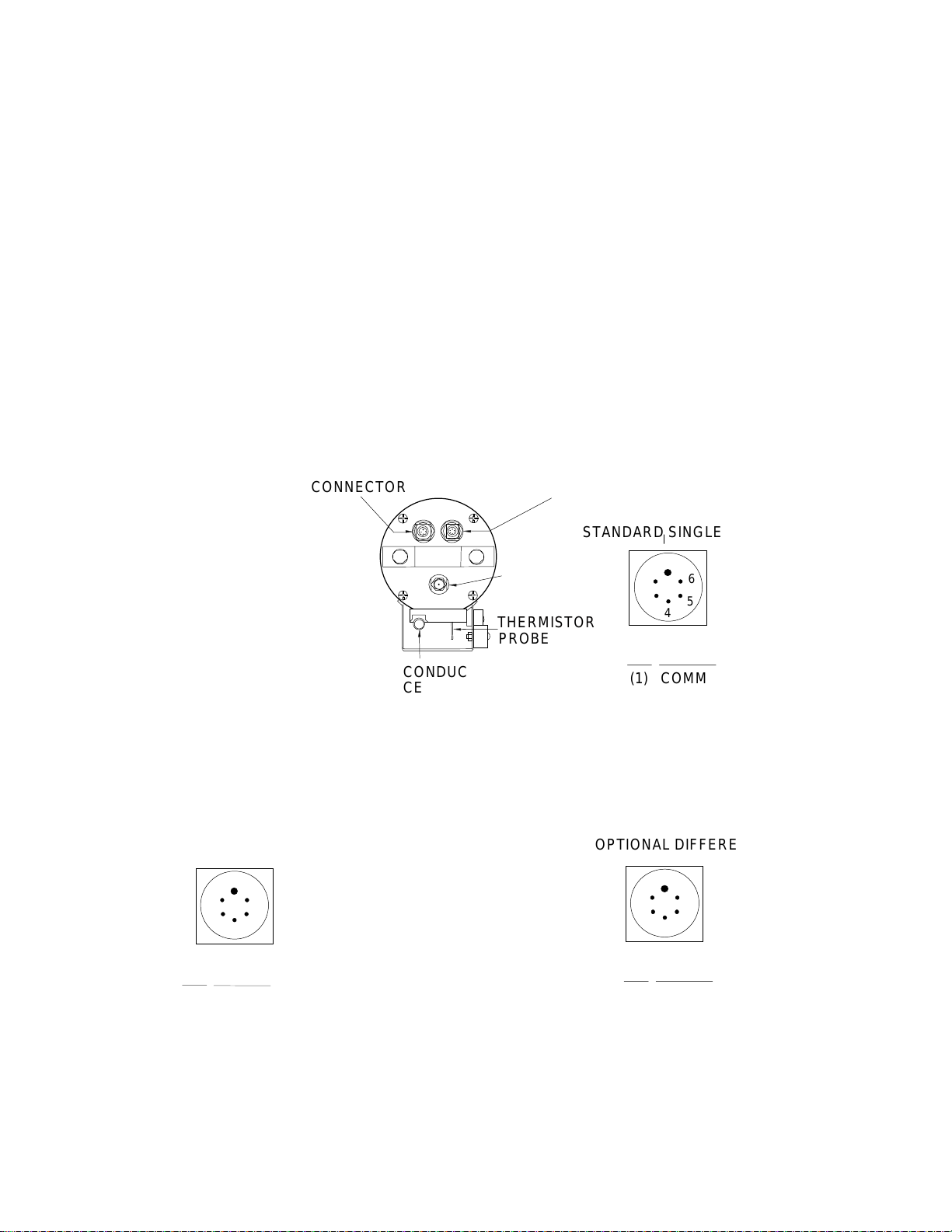
The SEACAT Profiler’s standard configuration includes an externally mounted SBE 5M submersible pump,
used to provide a constant flow rate through the conductivity cell. Optionally, if configured with a
dissolved oxygen sensor, pumped fluorometer, or SEACAT T-C Duct, the more powerful SBE 5T pump is
used. In either case, the pump is powered via a Y-cable connected to the 6-pin Data I/O bulkhead
connector on the end cap. Two pins provide power for the pump; the remaining four pins are for
communication and external power (Figure 1). The Y-cable has 2 branches: one connecting to the pump,
and the other providing the connection to a computer with a 4-pin male connector (RMG-4-MP) (figure 2).
If the Profiler is configured without a pump, it is supplied with a 6-pin to 4-pin adapter cable to connect
the Y-cable to the computer.
The SEACAT Profiler can be configured with a wide range of auxiliary sensors. A second 6-pin bulkhead
connector on the end cap serves as the input port for the auxiliary sensor signal voltages and provides
power to the sensors (Figure 1).
Figure 1 Connector Congurations for the SEACAT Profiler.
THERMISTOR
CONDUCTIVITY
INPUT/OUTPUT
(1) COMMON
(2) DATA RECEIVE
(3) DATA TRANSMIT
(4) AUX POWER IN
PIN SIGNAL
1
2
3
4
CONNECTOR
PROBE
CELL
(XSG-4BCL-HP)
1
2
345
6
(1) COMMON
(2) VOLTAGE 0
(3) VOLTAGE 3
(4) VOLTAGE 1
PIN SIGNAL
(AG-306-HP)
AUXILIARY INPUT
CONNECTOR
PRESSURE
PORT
(5) VOLTAGE 2
(6) AUX POWER OUT
(1) COMMON
(2) DATA RECEIVE
(3) DATA TRANSMIT
(4) PUMP POWER COMMON
PIN SIGNAL
1
2
345
6
(1) COMMON
(2) VOLTAGE 0 SIGNAL
(3) VOLTAGE 0 COMMON
(4) VOLTAGE 1 SIGNAL
PIN SIGNAL
(AG-306-HP)
(5) VOLTAGE 1 COMMON
(6) AUX POWER OUT
1
2
345
6
(AG-306-HP)
(5) PUMP POWER +
(6) AUX POWER IN
I/O CONNECTOR WITH OPTIONAL PUMP OPTIONAL DIFFERENTIAL INPUTS
STANDARD I/O CONNECTOR STANDARD SINGLE ENDED INPUTS
DATA I/O CONNECTOR

7
The SEACAT Profiler is configured with the SBE 5 pump to insure a reliable flow of water through the
conductivity cell and optional dissolved oxygen sensor regardless of descent rate. Figure 2 shows the
plumbing arrangement of a CTD equipped with a pump. Sections 2-2.6 and 3-1.2 of this manual contains
additional information on the configuration and operation of the pump.
Figure 3 shows the SEACAT Profiler configured with the pump and the optional SBE 23 dissolved oxygen
and SBE 18 pH sensors. Application note 29 included in this manual contains additional information
concerning the configuration of the SEACAT Profiler with optional sensors.
2-2 SEACAT PROFILER COMMUNICATION FUNDAMENTALS
SEACAT Profiler is factory configured for: 600 baud (1200 baud with optional Paroscientific pressure
sensor), 7 Data Bits, 1 Stop Bit, Even Parity. SEACAT Profiler outputs - and expects to receive - industry
standard RS-232 levels. If the TERM19 program is used to communicate with the SEACAT Profiler use the
F2 (function 2) key to set these parameters (see Section 2-5).
Remove the rubber cap from SEACAT Profiler's I/O bulkhead connector or from the I/O connector on the
pump Y-cable by pulling it firmly upward. Install the Sea-Bird I/O cable connector, aligning the raised bump
on the side of the connector with the large pin on the SEACAT connector. The other end of the I/O cable
has a DB-25S for connection to your computer's serial port.
Figure 2 SBE 19 with SBE 5 pump
Figure 3 SBE 19 with pump, and
optional dissolved oxygen and pH sensors
SBE 5 Pum
p
SBE 5 Pump

8
To begin communicating with SEACAT Profiler, the magnetic switch should be off. Mate the 4-pin test
cable to the computer's serial port. If you are using Sea-Bird SEASOFT software, the serial port must be
an IBM Asynchronous Communications Adapter, or equal. Run the TERM19 program and establish
communications with the Profiler. SEACAT Profiler is now in command mode and may be queried for
various responses as described in the following sections of this manual.
About two minutes of keyboard inactivity will cause SEACAT Profiler to time out and go into quiescent
state. To regain control, press the enter or carriage return key (CR) several times until the S> is displayed
again. After completing a session with SEACAT Profiler, enter qs(CR). This will make SEACAT Profiler
enter the quiescent state immediately.
If the board-mounted internal lithium battery has been removed, disconnected, or exhausted, set the date
and time with the ST command, set the pump parameters with the SP command, and enable the
acquisition of external voltages with the SV command if auxiliary sensors are installed.
2-2.1 COMMAND FORMAT
Commands to SEACAT Profiler can be entered in upper or lower case letters. Responses made by SEACAT
Profiler are indicated in bold type. SEACAT Profiler will send #whenever an invalid command is entered.
The following table describes the keyboard symbols used in this manual:
Symbol Description
ASCII
HEX
Key Sequence
(CR) Carriage Return CR 0D Return
NULL Null character NULL 00 Home Key
^ Control Key -- -- Ctrl
^C Escape Function ETX 03 Ctrl + C or
^C Escape Function ESC 1B Esc
When running TERM19, the Esc Key must be used to perform the Escape Function.
* Commands followed by * alter SEACAT Profiler memory and will prompt the user twice before
executing (* is not part of the command). To execute the command enter Y in response to message
Y/N then hold down the Ctrl key and enter Y in response to are you sure ^Y/N. Any other responses
will abort the command.
[] Braces indicate optional parameters of the command. Items enclosed in braces need not be entered.

9
2-2.2 EDITING
The following keys are used to edit entries to SEACAT Profiler.
Description
ASCII
HEX
Carriage return: enters the command or line CR 0D
Backspace: deletes the previous character BS 08
Kill line: Ctrl X CAN 18
Kill line: Escape ESC 1B
Kill line: Ctrl C ETX 03
2-2.3 COMMAND SUMMARY
Type
Command
Description
Diagnostics J Measure standby current
TE Extended memory test
TM Memory test
VR Display voltages
FR Display frequencies
Status DS Display current status
Setup CN Set conductivity channel to narrow range (fresh water)
CS Set conductivity channel to standard range (salt water)
IR Initialize ram
LW Set time to pause after each line (0 is the default)
MM Set mode to moored
MP Set mode to profiling
PN Disable pump control logic
QS Quit session, enter quiescent state
SB Change default baud rate for communications and real time data
SP Enable and set pump control parameters
SR Set sampling rate (profiling mode)
SI Set sample interval (moored mode)
ST Set date and time
SV Set the number of external voltages to sample
VD Set time to delay before measuring voltages in moored mode
Logging IL Initialize logging
GL Start logging, overwrite existing data
QL Quit logging in moored mode
RL Resume logging, do not overwrite data
HOME KEY or Ctrl-Z will halt logging in profiling mode
Data Retrieval DC Dump data by cast
DD Dump data by scans
DH Display headers

10
2-2.4 DIAGNOSTICS
J(CR) Measure Standby current.
TE(CR)*^C Extended memory test. WARNING, ALL DATA IN SEACAT PROFILER WILL BE
DESTROYED! An incrementing pattern is written into all locations of each RAM. Data in
the RAM is then compared to the pattern. Each pass the pattern is incremented by one.
Each pass takes approximately 20 seconds and the test concludes after 10 passes. For
each pass SEACAT Profiler sends the following message:
pass x
ram 0, OK
ram 1, OK
ram 2, OK
etc.
At the test conclusion or when an Escape Function character is received, SEACAT Profiler displays:
ram test passed with no errors.
NOTE: TE command not available in Profiler firmware version 4.0b or greater.
TM(CR)*^C Memory test. WARNING, ALL DATA IN SEACAT PROFILER WILL BE DESTROYED! Same
as extended memory test except that the test concludes after pass 0 is completed.
NOTE: TM command not available in Profiler firmware version 4.0b or greater.
VR(CR)^C Display voltages. The first column is the main battery voltage divided by 8.514. The
second column is a voltage that represents the temperature in the pressure sensor The
third column is the pressure sensor voltage. 0, 2 or 4 columns are added after the last
column depending on how many external voltages are sampled.
CAUTION: After execution of the VR command, SEACAT will run continuously until the Escape
Function is implemented. Unless an external power source is being used, the normal
170 mA current will be drawn from the battery during this time.
Example: VR(CR) SEACAT will send:
0.982 0.745 4.716
FR(CR)^C Display corrected and uncorrected frequencies.
CAUTION: After execution of the FR command, SEACAT will run continuously until the Escape
Function is implemented. Unless an external power source is being used, the normal
170 mA current will be drawn from the battery during this time.

11
Example: FR(CR) SEACAT will send:
aaaaa.aaa bbbbb.bbb ccccc.ccc ddddd.ddd eeeee.eee fffff.fff
aaaaa.aaa is the 400 ohm reference resistor frequency
bbbbb.bbb is the 5000 ohm reference resistor frequency
ccccc.ccc is the frequency generated by the temperature sensor
ddddd.ddd is the frequency generated by the conductivity cell
eeeee.eee is the corrected temperature frequency
fffff.fff is the corrected conductivity frequency
2-2.5 STATUS
DS(CR) Display operating status: software version, serial number and current time;
pressure sensor type, serial number, range and temperature compensation value
for strain gauge sensors; real time clock frequency, operating current (milliamps),
main battery voltage, lithium battery voltage; operating mode, number of stored
casts; sample rate; number of stored samples, number of samples free in
memory, and number of milliseconds to wait after sending a carriage return line
feed (provides extra time for slow computers); battery cut-off voltage; number of
external voltages that are being sampled; and whether data is being logged or
not (moored mode)
Example: DS(CR) SEACAT Profiler will send:
SEACAT PROFILER V3.1B SN 936 02/10/94 13:33:06.439
strain gauge pressure sensor: S/N = 12345, range = 1000 psia, tc = 240
clk = 32767.766 iop = 172 vmain = 8.1 vlith = 5.7
mode = PROFILE ncasts = 0
sample rate = 1 scan every 0.5 seconds
samples = 0 free = 174126 lwait = 0 msec
battery cutoff = 7.2 volts
number of voltages sampled = 0
logdata = NO
If the pump is installed and pump control is enabled via the SP command the pump control parameters will
be displayed.
SEACAT PROFILER V3.1B SN 936 02/10/94 13:33:23.989
strain gauge pressure sensor: S/N = 12345, range = 1000 psia, tc = 240
clk = 32767.766 iop = 172 vmain = 8.1 vlith = 5.8
mode = PROFILE ncasts = 0
sample rate = 1 scan every 0.5 seconds
minimum raw conductivity frequency for pump turn on = 3206 hertz
pump delay = 40 seconds
samples = 0 free = 174126 lwait = 0 msec
battery cutoff = 7.2 volts
number of voltages sampled = 0
logdata = NO

12
In moored mode the voltage sample delay is displayed.
SEACAT PROFILER V3.1B SN 936 02/10/94 13:33:39.549
strain gauge pressure sensor: S/N = 12345, range = 1000 psia, tc = 240
clk = 32767.766 iop = 172 vmain = 8.2 vlith = 5.6
mode = MOORED
sample interval = 30 seconds
delay before measuring voltages = 4 seconds
samples = 0 free = 174126 lwait = 0 msec
battery cutoff = 7.2 volts
number of voltages sampled = 0
logdata = NO
If narrow range conductivity has been selected this is displayed in the header.
SEACAT PROFILER V3.1B SN 936 02/10/94 13:33:23.989
strain gauge pressure sensor: S/N = 12345, range = 1000 psia, tc = 240
Narrow Range Conductivity
clk = 32767.766 iop = 172 vmain = 8.1 vlith = 5.8
mode = PROFILE ncasts = 0
sample rate = 1 scan every 0.5 seconds
minimum raw conductivity frequency for pump turn on = 2000 hertz
pump delay = 40 seconds
samples = 0 free = 174126 lwait = 0 msec
battery cutoff = 7.2 volts
number of voltages sampled = 0
logdata = NO
2-2.6 SETUP
SEACAT Profiler functions both as a profiling instrument and a moored or time series instrument. The
differences between these two modes involve how the data are stored and whether the SEACAT runs
continuously or powers off between samples.
In profiling mode the instrument runs continuously, drawing the full operating current from the main
battery supply. The unit samples at two samples per second. If the sample rate is set to a slower value,
the unit continues to sample at two samples a second but only stores data at the specified rate. The
longest period between samples is 4 minutes. Temperature and conductivity data are stored as
uncorrected frequencies. The necessary reference frequencies to convert the data to corrected frequencies
are stored every 120 samples. See Section 2-3 on data formats for additional information.
Commands that only affect profiling mode are:
PN Disable pump control logic
SP Set pump control parameters
SR Set sampling rate
DC Dump data by casts (see Section 2-2.9)

13
In moored mode the instrument powers down between samples. The fastest sample rate is once every 15
seconds. The default amount of time that SEACAT Profiler will provide power to external sensors before
sampling them is 4.0 seconds. This value can be increased to a maximum of 32,000 seconds with the VD
command for instruments such as the Sea Tech fluorometer that need a longer time to come to a stable
value. In particular, dissolved oxygen sensors require between two and three minutes to polarize after
application of power to the sensor. The voltage delay should be set to a minimum of 120 seconds and the
sample interval to a minimum of 150 seconds if an oxygen sensor is installed. The pump will be powered
for the entire time power is applied to the auxiliary sensors. The increased power going to pump will limit
the number of samples that can be taken to between 350 and 400 when the voltage delay value is set to
120 seconds for an oxygen sensor. The temperature and conductivity data are stored as corrected
frequencies.
Commands that only affect moored mode are:
SI Set sample interval
VD Set time to delay before measuring voltages in moored mode
All SEACAT Profilers are built with the capabilities to record external voltages. If the instrument was
ordered without auxiliary sensors, the number of voltages that the unit acquires was set to zero to
conserve memory usage. The SV command is used to enable this function if an auxiliary sensor is added
at a later date. Corresponding changes to the software configuration files also have to be made for the
SEASOFT software to recognize this change
CN(CR) Set conductivity channel to narrow range (fresh water 0 - 0.6 S/m)
If narrow range is set the line 'Narrow Range Conductivity' will displayed in the status.
CS(CR) Set conductivity channel to standard range (salt water 0 - 6.5 S/m)
IR(CR)*^C Initialize RAM (memory): WARNING, ALL DATA WILL BE DESTROYED! All data bits are set
to 0. Sample number, header number, and data pointers are set to 0. Allow 1.5 minutes to
reset the entire memory. Memory initialization is optional, as SEACAT Profiler will write over
previously recorded information when the gl command (see below) is used. However,
knowledge of the initial memory contents (i.e., all zeros) can be a useful cross check when
data is retrieved.
LWN(CR) Set wait interval of N milliseconds after each line of data; normally N = 0; increase for slower
computers. Nmax = 65535.
MM(CR) Set mode to moored.
MP(CR) Set mode to profiling.
PN(CR) Disable pump control logic.
QS(CR) Quit session. Puts SEACAT Profiler in quiescent mode (50 microamps). Use this command
and then wait 3 seconds before turning on the magnetic switch when in profiling mode.
SBn(CR) Change baud rate used by the SEACAT during normal communications.

14
Upon initial power up or reset the SEACAT Profiler will default to communicating at 600 baud. This
command allows the user to change this baud rate to one of the values listed below. When this command
is given, the SEACAT will immediately change its baud rate and all subsequent communication will be at
the new baud rate. This baud rate will be retained by the SEACAT until power is removed from the circuit
boards (caused by disassembly or by using the reset switch located on the battery bulkhead) or until a
new SB command is entered. The new baud rate is retained while the SEACAT is in quiescent mode
between samples. This setting does not affect the baud rate controlled by the DD and DC commands for
uploading data from the SEACAT.
The possible values are:
n = 1 600 baud
n = 2 1200 baud
n = 3 9600 baud
Example: SB3 set baud rate to 9600
SP(CR) For the pump to prime properly at the surface, it is necessary for the pump and tygon tubing to be
filled with water before the pump is turned on. This command sets the pump turn on parameters.
You will be asked:
minimum raw conductivity frequency for pump turn on = xxxx new value =
Enter a new value to change the minimum frequency or press carriage return to accept the current value.
The configuration sheet at the beginning of the manual lists the uncorrected (raw) frequency output at 0
conductivity. For most salt water and estuarine applications, enter the 0 conductivity frequency + 500 Hz
(factory default) as the minimum frequency. For fresh water, 5 Hertz above the 0 conductivity frequency
is typically used.
pump delay time (seconds) = xxx, new value =
Enter a new value to change the delay time or press carriage return to accept the current value. A value of
30 to 45 seconds should give ample time for the tygon tubing and pump to fill with water after the Profiler
has been submerged.
The pump will start after the delay time, and after the conductivity cell's frequency output is greater than
the minimum raw conductivity frequency. The pump will stop as soon as the raw conductivity frequency
drops below the minimum.
See Data Format (Section 2-3) for details on computing raw conductivity frequency from HEX data.
SR(CR) Set sample rate as prompted for profiling mode.
Example: SR(CR) SEACAT Profiler will prompt:
number of 0.5 sec intervals between samples = 1
the sample rate is 1 scan every 0.5 seconds
The maximum allowable number of 0.5 second intervals between samples is 480 (4 minutes between
samples).

15
SI(CR) Set sample interval as prompted for moored mode.
Example: SI(CR) SEACAT Profiler will prompt:
number of seconds between samples = 60
sample interval = 60 seconds
The minimum sample interval is 15 seconds, the maximum is 32000 seconds.
ST(CR) Set date and time as prompted
Example: ST(CR)
date (MMDDYY) = 042387(CR)
time (HHMMSS) = 191026(CR)
The date is set to April 23, 1987. The time is set to 19:10:26.
SVN(CR) Set the number of external voltages to sample as prompted.
Example: SV2(CR) will set the number of voltages to acquire to 2.
The possible values are 0, 2, or 4 voltages.
Enter a new value that reflects the number of external voltages that are to be recorded through the 6-pin
auxiliary connector on the end cap. If the number of voltages is changed, a corresponding change must be
made in the software configuration files for the SEASOFT software to recognize the change.
VDN(CR) Set the time to delay before measuring external voltages in moored mode.
Example: VD11(CR) will add 11 seconds to the default value of 4.0 seconds.
The default and minimum value is 4.0 seconds. The maximum value is 32000 seconds. N is entered in
seconds. If a Sea Tech Fluorometer is installed, N should be 11 seconds (delay of 15 seconds). If an
oxygen sensor is installed, N should be a minimum of 116 seconds (delay of 120 seconds).

16
2-2.7 LOGGING
In profiling mode, data logging can be initiated by turning on the magnetic switch while the SEACAT
Profiler is in the quiescent state or by using the GL or RL commands when the CPU is active and the
magnetic switch is on. Turning on the magnetic switch while the CPU is active will not start logging. If the
switch is left on when the unit is put in the quiescent state (either by using the QS command or by timing
out), the unit will start logging when the next attempt to establish communications is made. Logging
commences approximately 5 seconds after the movement of the switch or the receipt of the GL or RL
command. The first time the switch is turned on after receipt of the IL command, the data recording will
start at the beginning of memory and any previously recorded data will be written over, whether the
memory has been initialized or not. When the switch is subsequently turned off, recording will stop. Each
time the switch is turned on again, recording will continue with new data stored after the previously
recorded data and a new header written to indicate the time, date, incremented cast number, and sample
numbers contained in the cast. The maximum number of casts that can be taken is 100.
In moored mode, logging is initiated by using the GL or RL commands. The switch should be left in the off
position, but has no effect on logging. If the switch is turned on while the SEACAT profiler is in the
quiescent state and in moored mode, the CPU will enter the active state but logging will not begin. If no
communications are established the unit will time out and enter the quiescent state after 3 minutes.
In both profiling and moored mode, data is transmitted real time at 600 baud (1200 baud if the optional
Paroscientific Digiquartz pressure sensor is installed), or at the baud rate specified with the SB command.
If memory is filled to capacity, data logging and the transmission of real time data will continue, but
excess data will not be saved in memory.
IL(CR)* Initialize logging. Use this command to reset data pointers and the cast number after existing
data has been removed from SEACAT Profiler and prior to recording new data.
GL(CR)* Go log. Start logging data. For this command to work in profiling mode, the magnetic switch
must be on. The first scan is set to 0 so any previously recorded data will be written over,
whether the memory has been initialized or not. This command is useful for laboratory testing
of SEACAT Profiler when in profiling mode.
QL(CR) Quit logging data in moored mode. When logging data in moored mode, SEACAT Profiler will
respond only to the DS, QS and QL commands. The QL command is given when
communications have been established with SEACAT Profiler and the S> prompt is present.
RL(CR)* Resume logging data. Same as gl command except that the sample number is not reset.
Previously recorded data will not be overwritten. In profiling mode a new cast is started. In
moored mode data is stored after the last previously stored sample.
Table of contents
Other Sea-Bird Electronics Measuring Instrument manuals


Popular Measuring Instrument manuals by other brands


Texmate
Texmate Tiger 320 Series Programming guide

Suaoki
Suaoki PF3S Series user manual

AEP transducers
AEP transducers DYNAMIC STAR user guide

Ascon tecnologic
Ascon tecnologic TRH324 user manual

CWE
CWE MicroCapStar instruction manual

Ametek
Ametek Drexelbrook 505-1320 Series Installation and operating instructions