Sea Catch TR3 User manual

Estimated Effort to Release Load
The estimated effort to pull on the Sea Catch release
line to release capacity load is as follows:
Model SWL Effort to release
TR03 .65 tons 8 lbs / 3.62 kgs
TR05 1.66 tons 30 lbs / 13.6 kgs
TR07 3.52 tons 40 lbs / 18 kgs
TR08 4.78 tons 88 lbs / 40 kgs
TR10 7.92 tons 145 lbs / 65 kgs
TR11* 14.08 tons 258 lbs / 117 kgs
TR12* 16.42 tons 301 lbs / 136 kgs
TR15* 25.10 tons 460 lbs / 208 kgs
TR16* 31.68 tons 580 lbs / 263 kgs
TR17* 47.37 tons 867 lbs / 394 kgs
TR18* 77.11 tons 1411 lbs / 640 kgs
*Alternative release methods shown on page 6.
Product Disclaimer
The specifications information and performance of the products manufactured by McMillan
Design (MD) and featured in this publication may be changed without notice. This web version of
the User's Manual takes precedence over other versions. While MD does everything within its
control to ensure all its products have an appealing appearance free of defects and surface
deformations, some cosmetic irregularities may be present but do not impair the integrity,
function or performance of the product. Since the use of this information and the conditions by
which the products are used are beyond the control of MD, it is the obligation of the owner and/or
the equipment operator to carefully read and understand the Sea Catch User’s Manual and
determine the correct and safe selection and settings and conditions of use of the equipment
and products. While components manufactured by others such as hydraulic or air cylinders,
squibs or cartridges that are fitted to MD products are selected for optimum function, durability
and appearance, MD is not responsible for loss or damage caused by their malfunction or part
failure, while operating the device in or out of water. MD is not responsible for damages to
persons or property caused by loads such as dynamic loads, hydrodynamic loads and/or inertial
loads that cause the overall load to exceed the safe working load (SWL) of that product,
damages to persons or property caused by failure of a product that has been welded, or
otherwise altered by the product’s owner. To the extent that the law permits, any liability which
may be incurred as a result of the use or future use of a product manufactured or sold by MD is
limited to the cost of repairing or replacing the failed product or component at the discretion of
MD, either within, or outside of warranty periods, and does not extend to any loss or damage
which may be caused as a consequence of misuse or failure of the equipment or products. MD,
its owner(s), its shareholder(s), or its agents shall not in any event be liable for economic loss of
profits, indirect, special, bodily injuries or consequential damages. By virtue of taking possession
of any product manufactured by MD, the owner and/or the equipment operator agrees to the
terms of this Disclaimer.
©
Copyright 2015 McMillan Design, Inc.
All rights reserved by McMillan Design, Inc.
May not be copied in whole or part.
Sea Catch
®
is a registered trademark of McMillan Design, Inc.
Sea Catch is protected under US Pat. No. 5901990.
See your dealer or contact:
McMillan Design, Inc.
9816 Jacobsen Lane
Gig Harbor, WA 98332 USA Website: WWW.SEACATCH.COM
Tel: 253-858-1985 Fax: 253-858-1986 Email: sales@seacatch.com
Sea Catch
User’s Manual
Before operating the Sea Catch device, please carefully read and
u
nderstand this document for your safety and the safety of others
.
September 23, 2015
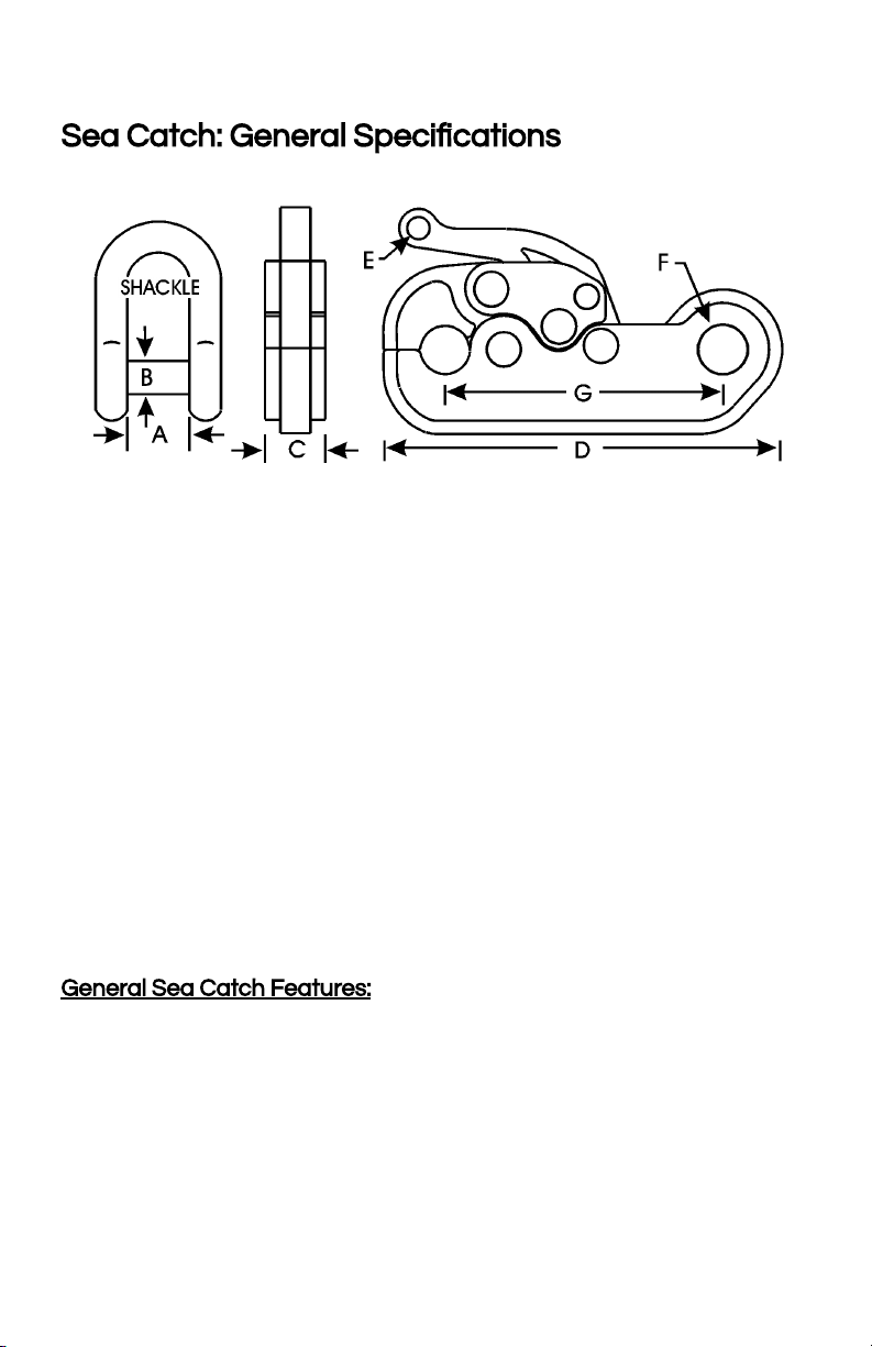
Sea Catch: General Specifications
Mod. Shackle A B C D E F G SW Load Break Ld. Weight
Size (in) in(mm) lb (sh ton) lb (sh ton) lb (kg)
TR3 1/4 .47 .31 .41 2.85 .18 .37 1.96 1,302 6,510 .31
(11.93) (7.87) (10.41) (73.39) (4,57) (9.39) (49.78) (.65) (3.2) (.14)
TR5 7/16 .75 .50 .69 4.5 .25 .55 3.13 3,323 16,618 1.3
(19.05) (12.7) (17.52) (114.3) (6.35) (13.97) (79.50) (1.6) (8.3) (.58)
TR7 5/8 1.06 .75 1 6.62 .38 .81 4.56 7,042 35,210 4
(26.92) (19.05) (25.40) (168.14) (9.65) (20.57) (115.82) (3.52) (17.6) (1.81)
TR8 3/4 1.25 .87 1.19 7.68 .43 .93 5.53 9,574 47,870 6.3
(31.75) (22.09) (30.22) (195.07) (10.92) (23.62) (140.46) (4.78) (23.93) (2.85)
TR10 1 1.69 1.13 1.63 9.75 .56 1.21 6.87 15,840 79,200 12.5
(42.92) (28.70) (41.40) (247.65) (14.22) (30.73) (174.49) (7.92) (39.6) (5.67)
TR11 1-3/8 2.25 1.50 2.12 13.15 .75 1.63 9.15 28,000 140,000 32
(57.15) (38.1) (53.84) (334.01) (19.05) (41.40) (232.41) (14) (70) (14.5)
TR12 1-1/2 2.38 1.62 2.25 14.25 .81 1.78 9.92 32,860 164,300 40
(60.45) (41.14) (57.15) (361.95) (20.57) (45.21) (251.96) (16.43) (82.15) (18.14)
TR15 1-3/4 2.88 2 2.75 17.56 1 2.16 12.21 50,200 251,000 69
(73.15) (50.8) (69.85) (446.02) ( 25.4) (54.86) (310.13) (25.1) (125.5) (31.29)
TR16 2 3.25 2.25 3.13 19.73 1.12 2.46 13.75 63,380 316,900 108
(82.55) (57.15) (79.5) (501.14) (28.44) (62.48) (349.25) (31.69) (158.45) (48.98)
TR17 2-1/2 4.15 2.75 3.88 24.13 1.37 3.01 16.81 94,740 473,700 197
(104.90) (69.85) (98.55) (612.90) (34.79) ( 76.45) (426.97) (47.37) (236.85) (89.35)
TR18 3 5 3.25 4.75 30.79 1.75 3.85 21.43 154,240 771,200 360
(127) (82.55) (120.65) (782.06) (44.45) (97.79) (544.32) (77.12) (385.6) (163.2)
inch (mm) lb (ton) lb (ton) lb (kg)
SWL (capacity) is a ratio of 5:1 to Breakload.
Products are constantly being improved. Designs, dimensions, capacities
and weights are subject to variation.
General Sea Catch Features:
- Perpendicular or parallel release directions
- Hitch pin lock for device locking safety
- Computer generated parts precision-cut from aerospace grade stainless
steel plate
- Low friction, low effort lanyard-style release for maximum user safety
- On Load / OffLoad Releasing
- All parts 100% stainless steel
- No springs
2
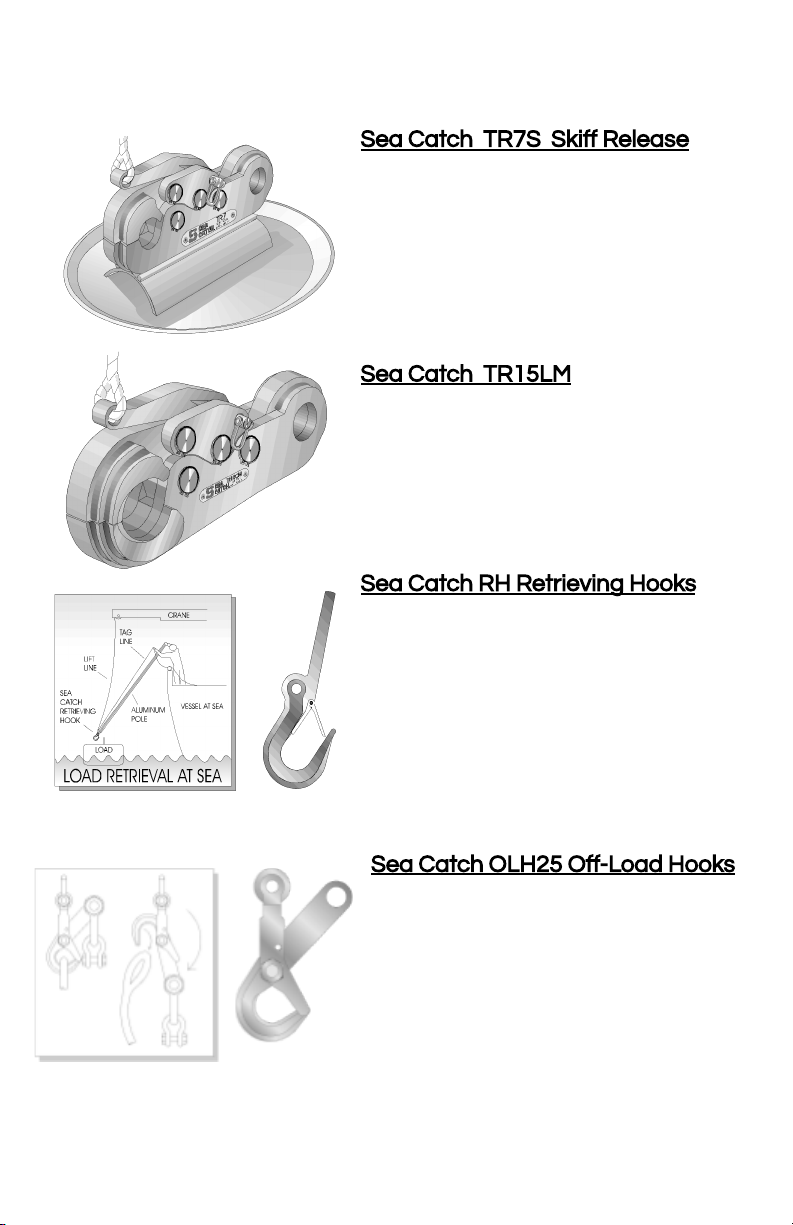
Sea Catch TR7S SkiffRelease
A standard TR7 is securely mounted
to a stainless steel dish. This stable
base allows the unit to function
dependably above seine gear during
purse seine skiffrelease applications.
Low kick-back, quiet operation, and a
safe hitch pin securement are key
elements for skiffrelease operations.
Sea Catch TR15LM
This is a
modified TR15 provided with a front
jaw enlarged to receive up to 3.4” fibre
line. Additional side plates at the jaw
area help spread the load and prevent
line chafing. Other capacities are
available.
Sea Catch RH Retrieving Hooks
These retrieving hooks are light weight
and strong. Used with a pole spike, the
hook is ideal for safe retrieval and
recovery of loads at sea. A tag line
holds the hook in the end of the pole
and controls the load once the pole is
removed.
Sea Catch OLH25 Off-Load Hooks
This is a pivoting hook (SWL: 4.5 m
tons) sized to receive up to 3” (7.62
cm) diameter line or strap.
Counter-weights can be shackles.
The hook automatically rotates and
releases the load line when load
reaches seabed. Other sizes
available.
7
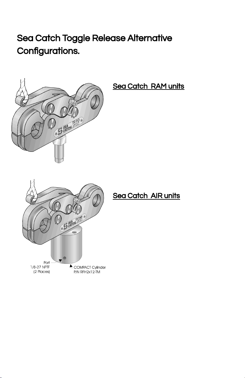
Sea Catch Toggle Release Alternative
Configurations.
Sea Catch RAM units
Standard models may be fitted with
hydraulic cylinders and fired
hydraulically. Above the cylinder is a
plunger which activates the release
from below. Cylinders are rated at
5,000 psi and provide larger capacity
units the necessary means for
activation.
Sea Catch AIR units
Standard models may be fitted with
air cylinders and fired with 100 psi
shop air. Air cylinders are suitable for
low capacity units and for
applications where hydraulic ones are
not suitable.
6
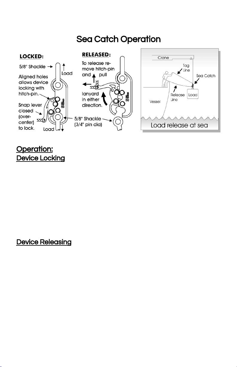
Sea Catch Operation
Operation:
Device Locking
Having secured the recommended shackle to the rear end of the Sea
Catch, open the jaw by removing the hitch pin and prying up the
release lever and opening it to the released position. Insert the pin of
the shackle to be released into the jaw opening.
Secure the shackle by closing the release lever to the locked position
and firmly lock the toggle pin over center with a vice-grip-like snap.
The shackle is now held firmly locked even with no load on the
device. The hitch pin can be reinserted to prevent inadvertent release.
The Sea Catch is now ready to be loaded. Once the hitch pin is
removed, the Sea Catch is armed and ready to be released.
Device Releasing
Release of the loaded Sea Catch is activated by first removing the
hitch pin and then pulling firmly on a release line connected to the end
of the release lever. The release line can be activated in any direction
within the 90 degrees perpendicular and parallel to the line of load.
The Sea Catch can be released with or without load on the unit.
The use of the hitch pin is not required to secure the device in the
locked position. It is an added safety measure preventing inadvertent
release. A hitch pin is provided with each unit.
3
!! Warnings !!
●Improper use and improper care of the Sea Catch device may cause injury.
●Hitch-pin must be used to prevent inadvertent release.
●Do not use the release line as a tag line or put any tension on it until time to
release. An additional tag line secured to the upper shackle (illustrated pg. 3)
and kept taught at all times is highly recommended to maintain a slack
release line and prevent load twisting.
●Stay clear of all objects released under load.
●Do not exceed the SWL capacity of your Sea Catch.
●Do not side load. Side loading may cause permanent damage to the unit.
●While in its loaded position, do not obstruct the Sea Catch from following the
line of the load. Misalignment may prevent release due to binding.
●Do not mount the Sea Catch such that the mounting fixture damages the
unit while in use. This could cause loss of parts and unit malfunction.
●Alterations to the Sea Catch by way of cutting, welding, and/or grinding voids
the unit load rating and product warranty.
The warnings stated in the web version of the User's Manual take precedence over
other versions of the Sea Catch User's Manual.
Safety Guidelines
●Inspection of the Sea Catch device is advised after each use. Should the
device be held in a static state under load, inspection should occur every 1-3
months depending on the severity of its corrosive environment.
●While in use in heavy marine environments or stored for long periods, a quick
fresh water rinse and a coating of WD40 or other suitable corrosion
retardant is advised. Always store the device in its closed and locked position
●Inspect every retainer ring for corrosion, proper installation and securely
seated in its groove. Corroded retainer rings are an early sign of improper
care and must be replaced.
●All pivot pins must be straight and rotate freely when under no load and in
the open position.
●Pivot pins may require periodic re-lubrication. AQUALUBE is recommended
for general use on sizes TR03 - TR11. Sizes TR12 and up require a grease
with moly added such as McMaster-Carr item #10605K42. Pivot pins should
be marked and returned to the same bore they were originally installed.
●Inspect the Sea Catch shackle eyes, jaws and pin holes for stretching
(elongation) and wear. Elongation means the unit is being overloaded.
●Inspect the Sea Catch body and jaws for bending. A bent body or jaws
indicates excessive side-loading.
●Inspect all Sea Catch pins and unit body and jaws for distortion, surface
blemishes, wear and fractures.
●Should the device become “soft” (little or no effort to open or close it), it is
unsafe to use and should be returned to McMillan Design for a $50
refurbishment which includes surface cleaning, attending to any issue with
function (cost of replacement parts are not included) and re-lubrication.
●Discontinue use and replace or send Sea Catch in to be rebuilt/refurbished
that are bent or fractured, show excessive wear by more than 10% of the
original dimension, have elongated pivot pin bores or shackle pin holes, or
have soft/missing over center snap.
4
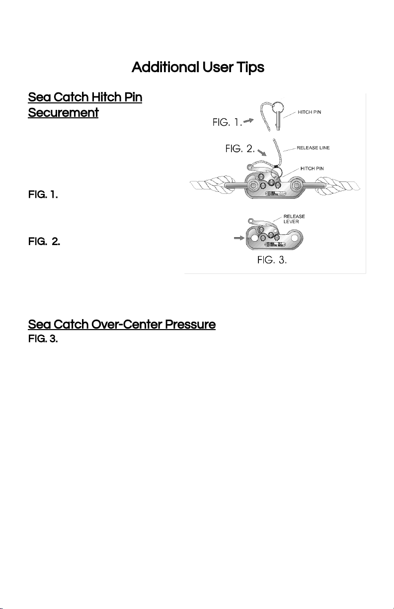
Additional User Tips
Sea Catch Hitch Pin
Securement
To prevent the loss of the
hitch pin, two methods of
securing it to the release line
are suggested:
FIG. 1.
The first option is to tie
the hitch pin to the outer end
of the release line.
FIG. 2.
The second method is
to secure the hitch pin at a
point near the inner end of
the release line as shown.
This method not only provides hitch pin securement but may facilitate
its removal at the time of release.
Sea Catch Over-Center Pressure
FIG. 3.
Ample material has been left at the tip of the movable jaw (see
arrow) where the jaw and body come in contact. This holds the device
securely over-center in the locked position even when no load is
applied to the device. It also helps prevent inadvertent release of the
device.
Should the user require that the effort to lock the release lever of the
device over-center be reduced, locate the area where the surface of
the jaw tip comes in contact with the body tip and lightly file or grind
offmaterial in that area. It is important to test the effort frequently
after some material has been removed so as to prevent the removal of
too much material.
To increase over-center effort, increase the thickness of the material
between the two surfaces by applying a center punch mark in the
area of the jaw where the surfaces meet. Should there still be
insufficient material to ensure the positive locking integrity of the
device, the contact area of the jaw will need to be spot-welded then
ground to the appropriate thickness.
5
!! Warnings !!
●Improper use and improper care of the Sea Catch device may cause injury.
●Hitch-pin must be used to prevent inadvertent release.
●Do not use the release line as a tag line or put any tension on it until time to
release. An additional tag line secured to the upper shackle (illustrated pg. 3)
and kept taught at all times is highly recommended to maintain a slack
release line and prevent load twisting.
●Stay clear of all objects released under load.
●Do not exceed the SWL capacity of your Sea Catch.
●Do not side load. Side loading may cause permanent damage to the unit.
●While in its loaded position, do not obstruct the Sea Catch from following the
line of the load. Misalignment may prevent release due to binding.
●Do not mount the Sea Catch such that the mounting fixture damages the
unit while in use. This could cause loss of parts and unit malfunction.
●Alterations to the Sea Catch by way of cutting, welding, and/or grinding voids
the unit load rating and product warranty.
The warnings stated in the web version of the User's Manual take precedence over
other versions of the Sea Catch User's Manual.
Safety Guidelines
●Inspection of the Sea Catch device is advised after each use. Should the
device be held in a static state under load, inspection should occur every 1-3
months depending on the severity of its corrosive environment.
●While in use in heavy marine environments or stored for long periods, a quick
fresh water rinse and a coating of WD40 or other suitable corrosion
retardant is advised. Always store the device in its closed and locked position
●Inspect every retainer ring for corrosion, proper installation and securely
seated in its groove. Corroded retainer rings are an early sign of improper
care and must be replaced.
●All pivot pins must be straight and rotate freely when under no load and in
the open position.
●Pivot pins may require periodic re-lubrication. AQUALUBE is recommended
for general use on sizes TR03 - TR11. Sizes TR12 and up require a grease
with moly added such as McMaster-Carr item #10605K42. Pivot pins should
be marked and returned to the same bore they were originally installed.
●Inspect the Sea Catch shackle eyes, jaws and pin holes for stretching
(elongation) and wear. Elongation means the unit is being overloaded.
●Inspect the Sea Catch body and jaws for bending. A bent body or jaws
indicates excessive side-loading.
●Inspect all Sea Catch pins and unit body and jaws for distortion, surface
blemishes, wear and fractures.
●Should the device become “soft” (little or no effort to open or close it), it is
unsafe to use and should be returned to McMillan Design for a $50
refurbishment which includes surface cleaning, attending to any issue with
function (cost of replacement parts are not included) and re-lubrication.
●Discontinue use and replace or send Sea Catch in to be rebuilt/refurbished
that are bent or fractured, show excessive wear by more than 10% of the
original dimension, have elongated pivot pin bores or shackle pin holes, or
have soft/missing over center snap.
4
Additional User Tips
Sea Catch Hitch Pin
Securement
To prevent the loss of the
hitch pin, two methods of
securing it to the release line
are suggested:
FIG. 1.
The first option is to tie
the hitch pin to the outer end
of the release line.
FIG. 2.
The second method is
to secure the hitch pin at a
point near the inner end of
the release line as shown.
This method not only provides hitch pin securement but may facilitate
its removal at the time of release.
Sea Catch Over-Center Pressure
FIG. 3.
Ample material has been left at the tip of the movable jaw (see
arrow) where the jaw and body come in contact. This holds the device
securely over-center in the locked position even when no load is
applied to the device. It also helps prevent inadvertent release of the
device.
Should the user require that the effort to lock the release lever of the
device over-center be reduced, locate the area where the surface of
the jaw tip comes in contact with the body tip and lightly file or grind
offmaterial in that area. It is important to test the effort frequently
after some material has been removed so as to prevent the removal of
too much material.
To increase over-center effort, increase the thickness of the material
between the two surfaces by applying a center punch mark in the
area of the jaw where the surfaces meet. Should there still be
insufficient material to ensure the positive locking integrity of the
device, the contact area of the jaw will need to be spot-welded then
ground to the appropriate thickness.
5
Sea Catch Toggle Release Alternative
Configurations.
Sea Catch RAM units
Standard models may be fitted with
hydraulic cylinders and fired
hydraulically. Above the cylinder is a
plunger which activates the release
from below. Cylinders are rated at
5,000 psi and provide larger capacity
units the necessary means for
activation.
Sea Catch AIR units
Standard models may be fitted with
air cylinders and fired with 100 psi
shop air. Air cylinders are suitable for
low capacity units and for
applications where hydraulic ones are
not suitable.
6
Sea Catch Operation
Operation:
Device Locking
Having secured the recommended shackle to the rear end of the Sea
Catch, open the jaw by removing the hitch pin and prying up the
release lever and opening it to the released position. Insert the pin of
the shackle to be released into the jaw opening.
Secure the shackle by closing the release lever to the locked position
and firmly lock the toggle pin over center with a vice-grip-like snap.
The shackle is now held firmly locked even with no load on the
device. The hitch pin can be reinserted to prevent inadvertent release.
The Sea Catch is now ready to be loaded. Once the hitch pin is
removed, the Sea Catch is armed and ready to be released.
Device Releasing
Release of the loaded Sea Catch is activated by first removing the
hitch pin and then pulling firmly on a release line connected to the end
of the release lever. The release line can be activated in any direction
within the 90 degrees perpendicular and parallel to the line of load.
The Sea Catch can be released with or without load on the unit.
The use of the hitch pin is not required to secure the device in the
locked position. It is an added safety measure preventing inadvertent
release. A hitch pin is provided with each unit.
3
Sea Catch: General Specifications
Mod. Shackle A B C D E F G SW Load Break Ld. Weight
Size (in) in(mm) lb (sh ton) lb (sh ton) lb (kg)
TR3 1/4 .47 .31 .41 2.85 .18 .37 1.96 1,302 6,510 .31
(11.93) (7.87) (10.41) (73.39) (4,57) (9.39) (49.78) (.65) (3.2) (.14)
TR5 7/16 .75 .50 .69 4.5 .25 .55 3.13 3,323 16,618 1.3
(19.05) (12.7) (17.52) (114.3) (6.35) (13.97) (79.50) (1.6) (8.3) (.58)
TR7 5/8 1.06 .75 1 6.62 .38 .81 4.56 7,042 35,210 4
(26.92) (19.05) (25.40) (168.14) (9.65) (20.57) (115.82) (3.52) (17.6) (1.81)
TR8 3/4 1.25 .87 1.19 7.68 .43 .93 5.53 9,574 47,870 6.3
(31.75) (22.09) (30.22) (195.07) (10.92) (23.62) (140.46) (4.78) (23.93) (2.85)
TR10 1 1.69 1.13 1.63 9.75 .56 1.21 6.87 15,840 79,200 12.5
(42.92) (28.70) (41.40) (247.65) (14.22) (30.73) (174.49) (7.92) (39.6) (5.67)
TR11 1-3/8 2.25 1.50 2.12 13.15 .75 1.63 9.15 28,000 140,000 32
(57.15) (38.1) (53.84) (334.01) (19.05) (41.40) (232.41) (14) (70) (14.5)
TR12 1-1/2 2.38 1.62 2.25 14.25 .81 1.78 9.92 32,860 164,300 40
(60.45) (41.14) (57.15) (361.95) (20.57) (45.21) (251.96) (16.43) (82.15) (18.14)
TR15 1-3/4 2.88 2 2.75 17.56 1 2.16 12.21 50,200 251,000 69
(73.15) (50.8) (69.85) (446.02) ( 25.4) (54.86) (310.13) (25.1) (125.5) (31.29)
TR16 2 3.25 2.25 3.13 19.73 1.12 2.46 13.75 63,380 316,900 108
(82.55) (57.15) (79.5) (501.14) (28.44) (62.48) (349.25) (31.69) (158.45) (48.98)
TR17 2-1/2 4.15 2.75 3.88 24.13 1.37 3.01 16.81 94,740 473,700 197
(104.90) (69.85) (98.55) (612.90) (34.79) ( 76.45) (426.97) (47.37) (236.85) (89.35)
TR18 3 5 3.25 4.75 30.79 1.75 3.85 21.43 154,240 771,200 360
(127) (82.55) (120.65) (782.06) (44.45) (97.79) (544.32) (77.12) (385.6) (163.2)
inch (mm) lb (ton) lb (ton) lb (kg)
SWL (capacity) is a ratio of 5:1 to Breakload.
Products are constantly being improved. Designs, dimensions, capacities
and weights are subject to variation.
General Sea Catch Features:
- Perpendicular or parallel release directions
- Hitch pin lock for device locking safety
- Computer generated parts precision-cut from aerospace grade stainless
steel plate
- Low friction, low effort lanyard-style release for maximum user safety
- On Load / OffLoad Releasing
- All parts 100% stainless steel
- No springs
2
Sea Catch TR7S SkiffRelease
A standard TR7 is securely mounted
to a stainless steel dish. This stable
base allows the unit to function
dependably above seine gear during
purse seine skiffrelease applications.
Low kick-back, quiet operation, and a
safe hitch pin securement are key
elements for skiffrelease operations.
Sea Catch TR15LM
This is a
modified TR15 provided with a front
jaw enlarged to receive up to 3.4” fibre
line. Additional side plates at the jaw
area help spread the load and prevent
line chafing. Other capacities are
available.
Sea Catch RH Retrieving Hooks
These retrieving hooks are light weight
and strong. Used with a pole spike, the
hook is ideal for safe retrieval and
recovery of loads at sea. A tag line
holds the hook in the end of the pole
and controls the load once the pole is
removed.
Sea Catch OLH25 Off-Load Hooks
This is a pivoting hook (SWL: 4.5 m
tons) sized to receive up to 3” (7.62
cm) diameter line or strap.
Counter-weights can be shackles.
The hook automatically rotates and
releases the load line when load
reaches seabed. Other sizes
available.
7
Estimated Effort to Release Load
The estimated effort to pull on the Sea Catch release
line to release capacity load is as follows:
Model SWL Effort to release
TR03 .65 tons 8 lbs / 3.62 kgs
TR05 1.66 tons 30 lbs / 13.6 kgs
TR07 3.52 tons 40 lbs / 18 kgs
TR08 4.78 tons 88 lbs / 40 kgs
TR10 7.92 tons 145 lbs / 65 kgs
TR11* 14.08 tons 258 lbs / 117 kgs
TR12* 16.42 tons 301 lbs / 136 kgs
TR15* 25.10 tons 460 lbs / 208 kgs
TR16* 31.68 tons 580 lbs / 263 kgs
TR17* 47.37 tons 867 lbs / 394 kgs
TR18* 77.11 tons 1411 lbs / 640 kgs
*Alternative release methods shown on page 6.
Product Disclaimer
The specifications information and performance of the products manufactured by McMillan
Design (MD) and featured in this publication may be changed without notice. This web version of
the User's Manual takes precedence over other versions. While MD does everything within its
control to ensure all its products have an appealing appearance free of defects and surface
deformations, some cosmetic irregularities may be present but do not impair the integrity,
function or performance of the product. Since the use of this information and the conditions by
which the products are used are beyond the control of MD, it is the obligation of the owner and/or
the equipment operator to carefully read and understand the Sea Catch User’s Manual and
determine the correct and safe selection and settings and conditions of use of the equipment
and products. While components manufactured by others such as hydraulic or air cylinders,
squibs or cartridges that are fitted to MD products are selected for optimum function, durability
and appearance, MD is not responsible for loss or damage caused by their malfunction or part
failure, while operating the device in or out of water. MD is not responsible for damages to
persons or property caused by loads such as dynamic loads, hydrodynamic loads and/or inertial
loads that cause the overall load to exceed the safe working load (SWL) of that product,
damages to persons or property caused by failure of a product that has been welded, or
otherwise altered by the product’s owner. To the extent that the law permits, any liability which
may be incurred as a result of the use or future use of a product manufactured or sold by MD is
limited to the cost of repairing or replacing the failed product or component at the discretion of
MD, either within, or outside of warranty periods, and does not extend to any loss or damage
which may be caused as a consequence of misuse or failure of the equipment or products. MD,
its owner(s), its shareholder(s), or its agents shall not in any event be liable for economic loss of
profits, indirect, special, bodily injuries or consequential damages. By virtue of taking possession
of any product manufactured by MD, the owner and/or the equipment operator agrees to the
terms of this Disclaimer.
©
Copyright 2015 McMillan Design, Inc.
All rights reserved by McMillan Design, Inc.
May not be copied in whole or part.
Sea Catch
®
is a registered trademark of McMillan Design, Inc.
Sea Catch is protected under US Pat. No. 5901990.
See your dealer or contact:
McMillan Design, Inc.
9816 Jacobsen Lane
Gig Harbor, WA 98332 USA Website: WWW.SEACATCH.COM
Sea Catch
User’s Manual
Before operating the Sea Catch device, please carefully read and
understand this document for your safety and the safety of others.
September 23, 2015
This manual suits for next models
10
Table of contents
Popular Safety Equipment manuals by other brands


EDELRID
EDELRID CLIP SAVER manual

Honeywell
Honeywell VA201T Calibration Handbook

Powerfix Profi
Powerfix Profi CL-B01 Operation and safety notes

AccessPRO
AccessPRO INDUSTRIAL XB220H06K Technical instructions

Ronstan
Ronstan BB Orbit Block RF25109 20 Series User instructions

Federal Signal Corporation
Federal Signal Corporation RSL-WMLM INSTALLATION AND APPLICATION INSTRUCTIONS


