valmont Ezy-Guard HC User manual

HIGHWAY
High-Containment
Roadside Safety Barrier
Product Manual
EZY-GUARD HC High Containment Roadside Safety Barrrier
www.valmonthighway.com
MASH TL4
COMPLIANT
MASH TL3
COMPLIANT
Release 08/21

Release 08/21
High-Containment Roadside Safety Barrier
2
HIGHWAY
1.0 IntroductIon
Introducing Ezy-Guard HC, a member of
the Ezy-Guard family, the next generation
steel guardrail barrier providing superior
motorist safety and more metres of barrier
for your dollar.
Ezy-Guard HC is crash tested to the latest
performance standard distinguishing it
from all existing public domain guardrail
barrier systems in Australia.
The Z-post profile shields post edges
from vulnerable road users and provides
sectional strength when driving through
difficult conditions.
An Ezy-HC-Carriage is used to secure the
Thrie-beam rails to the posts eliminating
the requirement for blocking/offset pieces
and rail stiffening plates. This unique
connection provides a soft ride-down
for the occupants and smooth vehicle
containment and redirection.
2.0 SpecIfIcAtIonS
Ezy-Guard HC Z-Post Length: 2,000mm
Ezy-Guard HC Z-Post Mass: 19.5kg
Ezy-Guard HC System Mass: 28.8kg per metre
Rail Height Above Ground: 980mm
Z-Post Height Above Ground: 970mm
Post Spacing: 2,000mm
Ezy-Guard HC System Width: 245mm
MASH TL3 Crash Test Deflection: 1.16m
MASH TL4 Crash Test Deflection: 1.77m
Ezy-Guard HC Thrie-beam rails and Z-posts
are manufactured from hot-rolled steel
flat products in accordance with AS/NZS
1594. These items are hot dip galvanised
in accordance with AS/NZS 4680 after
fabrication leaving no surface untreated.
State specific product acceptance details are
available upon request from your local Ingal
representative. Acceptance of product variants
should be confirmed prior to installation.
60
140

Release 08/21
High-Containment Roadside Safety Barrier
3
HIGHWAY
Approach Transition Rail 1905mm
10001809
Departure Transition Rail 1905mm
10001811
W Beam 4000mm NLL
10000977
Thriebeam 4000mm NLL
10000837
Ezy-Guard HC Post 2000mm
10005540
Ezy-Guard 4 Post 1650mm
10007390
HC Carriage
10004116
Splice Bolt M16 x 32
10001248
Smart Carriage
10004115
Oversized M16 Nut
10001239
Carriage Bolt M16 x 30mm
10001832
BArrIer SeLectIon tABLe
Guardrail
System
Performance
Class Deflection Surface Mount
Option
Environmental
Protection
Ezy-Guard Smart MASH TL3 1.65m Yes Hot Dip Galv to AS/NZS 4680
Ezy-Guard 4 MASH TL3
NCHRP-350 TL4 1.65m Yes Hot Dip Galv to AS/NZS 4680
Ezy-Guard HC MASH TL4
MASH TL3
1.77m
1.16m Yes Hot Dip Galv to AS/NZS 4680
Approach Transition Rail 1905mm
10001809
Departure Transition Rail 1905mm
10001811
W Beam 4000mm NLL
10000977
Thriebeam 4000mm NLL
10000837
Ezy-Guard HC Post 2000mm
10005540
Ezy-Guard 4 Post 1650mm
10007390
HD Carriage
10004116
Smart Carriage
10004115
Hex Bolt M16 x 30mm
10001832
Splice Bolt M16 x 32
10001248
Oversized M16 Nut
10001239

Release 08/21
High-Containment Roadside Safety Barrier
4
HIGHWAY
Figure 1: Comparison of Crash Test Impact Severities
3.0 crASH teSt AnALYSIS
Crash test guidelines provide a minimum set of requirements
that a roadside barrier has to meet in order to demonstrate
its satisfactory impact performance.
Whilst crash test guidelines cannot include all possible impact
conditions that may be experienced in the real world, the
crash test matrix is selected to represent a “worst practical
condition” for a roadside barrier impact.
Ezy-Guard HC has been fully crash tested and evaluated
according to the specifications for Test Level 4 (TL4) of the
AASHTO Manual for Assessing Safety Hardware (MASH).
The MASH specification is an update to and supersedes
NCHRP Report 350 for the purposes of evaluating new safety
hardware devices.
In the revised standard AS/NZS 3845.1:2015, MASH has
been nominated as the basis of testing procedures for road
safety barrier systems.
The MASH TL4 crash test matrix requires the following
impacts;
• 1,100kg car travelling at 100km/h and 25 degrees.
•2,270kg pick-up travelling at 100km/h and 25 degrees.
•10,000kg truck travelling at 90km/h and 15 degrees.
Crash test impact conditions are defined by the mass, speed,
and angle of the impacting vehicle. Crash test standards
and performance levels can be compared by calculating the
impact severity (IS).
IS = ½ M (V sin θ)2
Where IS is the impact severity in joules (J), M is the test
inertial mass of the vehicle in kilograms (kg), V is the impact
speed in metres/second (m/s) and θis the impact angle in
degrees.
M
A
S
H
T
L
4
M
A
S
H
T
L
3
N
C
H
R
P
3
5
0
T
L
4
209.3 kj Impact Severity: 10,000kg rigid
truck travelling at 90km/h and 15 degrees
156.4 kj Impact Severity: 2,270kg pick-up
truck travelling at 100km/h and 25 degrees
132.3 kj Impact Severity: 8,000kg
truck travelling at 80km/h and 15 degrees

Release 08/21
High-Containment Roadside Safety Barrier
5
HIGHWAY
Figure 2: Ezy-Guard HC Considerations for
Vulnerable Road Users
4.0 conSIderAtIon for VuLnerABLe
roAd uSerS
Vulnerable road users include motorcyclists, pedestrians,
cyclists and other road users. Ezy-Guard HC has been
designed to provide consideration to vulnerable road users
as follows:
Rounded Post Corners.
The Z-post contains smooth, rounded post edges and
corners mitigating the risk and severity of fractures and/or
contusions.
Energy Absorbing, Ductile Z-Posts.
The Z-posts are designed to yield by bending near ground
level. This bending action absorbs impact energy reducing
the potential for post fracturing.A fractured or split guardrail
post presents a significant laceration hazard to vulnerable
road users.
The Ezy-Guard HC design does not contain any elements that
become projectiles and there are no aggressive edges.
Shielded Posts.
The innovative design of Ezy-Guard HC shields the top of the
supporting Z-posts by positioning the top of the rail above the
posts. This eliminates dangerous snag points, reducing the
potential for the barrier to dismount motorcyclists or cyclists.
This is a significant safety benefit compared to traditional
guardrail and cable barrier systems.

Release 08/21
High-Containment Roadside Safety Barrier
6
HIGHWAY
Figure 3: Ezy-Guard HC Width Comparison
5.0 feAtureS And BenefItS
5.1 Fully Compliant to MASH TL4
Ezy-Guard HC, a member of the Ezy-Guard family, is fully
compliant to MASH TL4.
The MASH TL4 test condition represents a larger impact
energy when compared to NCHRP 350 Test Level 4 impacts.
The MASH TL4 compliance demonstrates the systems ability
to contain and redirect the 10,000kg truck which is 2000kg
heavier than the NCHRP-350 TL4 truck.
5.2 Rapid Installation & Repair
Ezy-Guard HC installation can be up to twice as fast to install
than conventional guardrail barriers and unlike cable barrier
systems, no concrete is required.
The Ezy-Guard HC design uses fewer components and
features 2,000mm Z-posts that are rapidly driven into the
ground. The Z-post embedment depth is just 1,030mm, a
significant reduction when compared to other Thrie-beam
guardrail posts. This reduces installation time providing
significant cost savings.
Since the Z-posts are designed to yield by bending near
ground level, damaged posts can be removed easily which
reduces the time spent by work crews on the roadside.
5.3 Narrow Width
With a system width of just 245mm, Ezy-Guard HC is
significantly narrower than the traditional guardrail barriers
that incorporate the use of blocking pieces. Ezy-Guard HC
conserves valuable formation width and allows a greater
recovery width to be provided for errant vehicles.
1030
980
245
2000
385
805
2100
1275
585
865
2100
1215
G9 Thrie-beam G9 Modified Thrie-beam
MASH TL4
COMPLIANT
MASH TL3
COMPLIANT
High-Containment Roadside Safety Barrier

Release 08/21
High-Containment Roadside Safety Barrier
7
HIGHWAY
5.4 Installation in Rock, Asphalt or Concrete
Mowing Strips
The design of the Z-post differs from traditional posts in that
it relies on the yielding of the post by bending near ground
level rather than the yielding of the surrounding soil during a
vehicle impact. This makes the Z-post suitable for installation
in rock, asphalt or concrete mowing strips.
A traditional guardrail post is designed to absorb some crash
energy through post rotation in the soil prior to post failure.
Restraining these traditional posts by setting them in narrow
holes drilled into solid rock, by setting them in thick asphalt
layers or concrete, or by placing a mowing strip around the
posts can lead to a failure of the system to safely contain and
redirect the errant vehicle.
5.5 Manual Handling
Ezy-Guard HC uses fewer components than the public
domain guardrail systems. Z-posts weighing just 19.5kg are
lighter than traditional Thrie-beam C-posts. The lightweight
Z-post reduces manual lifting by installation crews.
The rounded edges of the Z-post provides a handlelike grip
when lifting, reducing the possibility of hand lacerations.
The Z-profile allows the installer to maintain a firm grip and
facilitates correct lifting techniques.
5.6 Locally Designed & Produced
Ezy-Guard HC is manufactured in Australia by Valmont
Highway using steel manufactured by BlueScope Steel.
Z-posts and rail are stamped providing traceability to
material mechanical and chemical analysis certificates. Hot
dip galvanising is performed internally by Ingal and daily
inspections ensure zinc thickness readings are in accordance
with AS/NZS standards.
5.7 Soft Ride-Down Decelerations
The Ezy-HC-Carriage controls the release of the Thrie-beam
rail from the Z-posts. This controlled release reduces the
potential for vehicle pocketing and provides a soft ridedown
for vehicle occupants.
High-Containment Roadside Safety Barrier

Release 08/21
High-Containment Roadside Safety Barrier
8
HIGHWAY
6.0 performAnce
Ezy-Guard HC provides protection from roadside hazards located
close to the edge of the travelled way. The sectional strength of
the Z-post reduces lateral deflection whilst providing controlled
containment and redirection.
Crash testing guidelines provide a set of requirements that is
“worst practical conditions”in order to demonstrate the barriers
impact performance. When the combined effects of vehicle
mass, impact speed and angle of impact are considered, the
testing criteria represents the extremes of impact conditions to
be expected in realworld situations.
6.1 Deflection
The MASH TL3 deection for Ezy-Guard HC is 1.16m and the
MASH TL4 deection is 1.77m. The NCHRP-350 TL4 deection
is 1.0m. A range of deections for TL2 and TL3 can be found
in Table 1a, whilst Table 1b shows deection and working
widths for the MASH TL4 10,000kg truck with various post
spacings.
6.2 Slopes
The maximum cross fall for an installation of Ezy-Guard HC
is 10H:1V (10%).
Proximity to a batter slope will depend on the required
containment level. For TL3 containment, the recommended
minimum oset from hinge point to back of post is 300mm for a
2H:1V slope. For a TL4 containment, the offset from face of rail
to the hinge point should be equal to the expected deection,
refer section 6.1.
Figure 4: Batter Proximity
Table 1a: Dynamic deflections under various post spacing and impact speeds
Containment Level
Vehicle: 2,270 kg Impact Angle: 25˚
Speed
(km/h)
Post Spacing (m)
2 1 0.5
Dynamic
Deflection (m)
MASH TL3 100 1.16 0.81 0.53
80 0.8 0.6 *
MASH TL2 70 0.69 0.5 0.27
60 0.59 0.35 *
Table 1b: MASH TL4 working width and dynamic deflections under various post spacing
Vehicle: 10,000 kg Impact Angle: 15˚ Speed: 90 km/h
Post Spacing (m) 2 1 0.5
Deflection (m) 1.77 1.27 0.5
Working Width (m) 2.46 1.88 1.16
* Not currently available. Please contact your local Ingal Civil representative for more information.

Release 08/21
High-Containment Roadside Safety Barrier
9
HIGHWAY
Figure 5: Clear Zone Requirement for the use of Departure Terminals
7.0 InStALLAtIon
7.1 Terminals
Guardrail end terminals are installed at the beginning and end
of a run of guardrail. Their primary purpose is to anchor the
longitudinal barrier and to minimise deflection. Crashworthy
terminals are typically used in locations where they can be
impacted end-on as they are designed to provide a soft
gating impact if impacted near the end rail.This prevents any
spearing of an errant vehicle. Part of the end-terminal may
also be redirective.
Ezy-Guard HC is installed at a system height of 980mm,
measured to the top of the rail.This height is compatible with
our asymmetric 1,905mm transition bracket and the TREND-
350 terminal, refer to installation drawings.
Terminals should be installed in accordance with the
proprietor’s drawings and specifications. Z-posts are not to
be used in the terminals unless approved by the proprietor.
The installation of terminals will typically incorporate the use
of blocking/offset pieces positioned between the posts and
rail. This will require the supporting posts to be offset from
the set-out line used for the installation of the Z-posts which
do not require blocking pieces.
In addition, the post spacing used in the terminals and
transitions may vary from the 2m spacing used for installation
of Ezy-Guard HC.The required post spacing for terminals and
transitions will be contained in the proprietor’s drawings.
approach terminal barrier departure terminal
A departure terminal can
only be used if located
outside the clear zone of
approac
h
termina
l
b
arrier
d
eparture termina
l
A
d
eparture termina
l
can
only be used if located
outs
i
de
t
h
e
c
l
ea
r z
o
n
e
o
f

Release 08/21
High-Containment Roadside Safety Barrier
10
HIGHWAY
7.2 Minimum Length Requirements
There are two geometric methods used to determine the likely
trajectory of a vehicle that leaves the road in the vicinity of a
roadside hazard and the minimum length of barrier required
to protect from this hazard.
The most common method is the run-out length method and
an alternative is a method based on angle of departure.
Prior to design or installation, designers should consult the
relevant road controlling authority to establish the local
jurisdictional practice as the methods may result in dierent
lengths. Both methods are detailed in the Austroads Guide
to Road Design – Part 6.3.
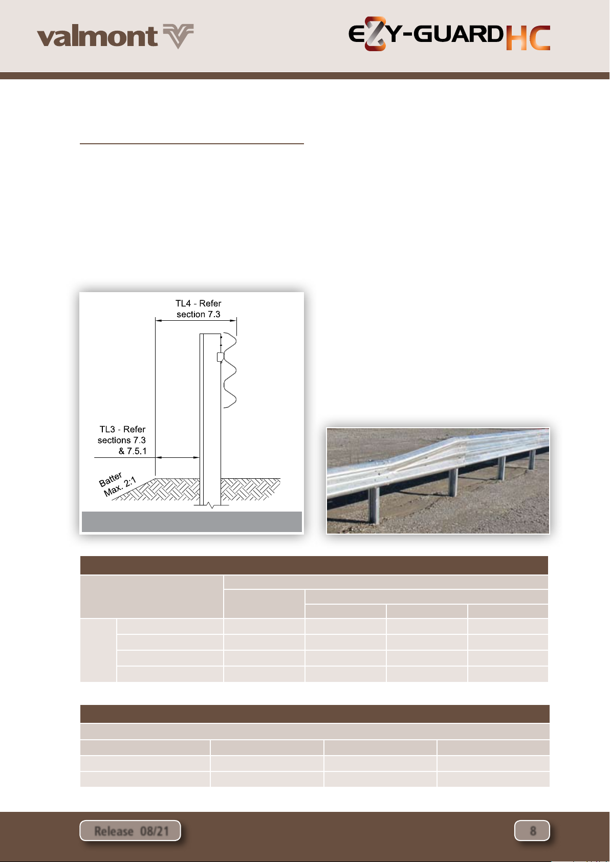
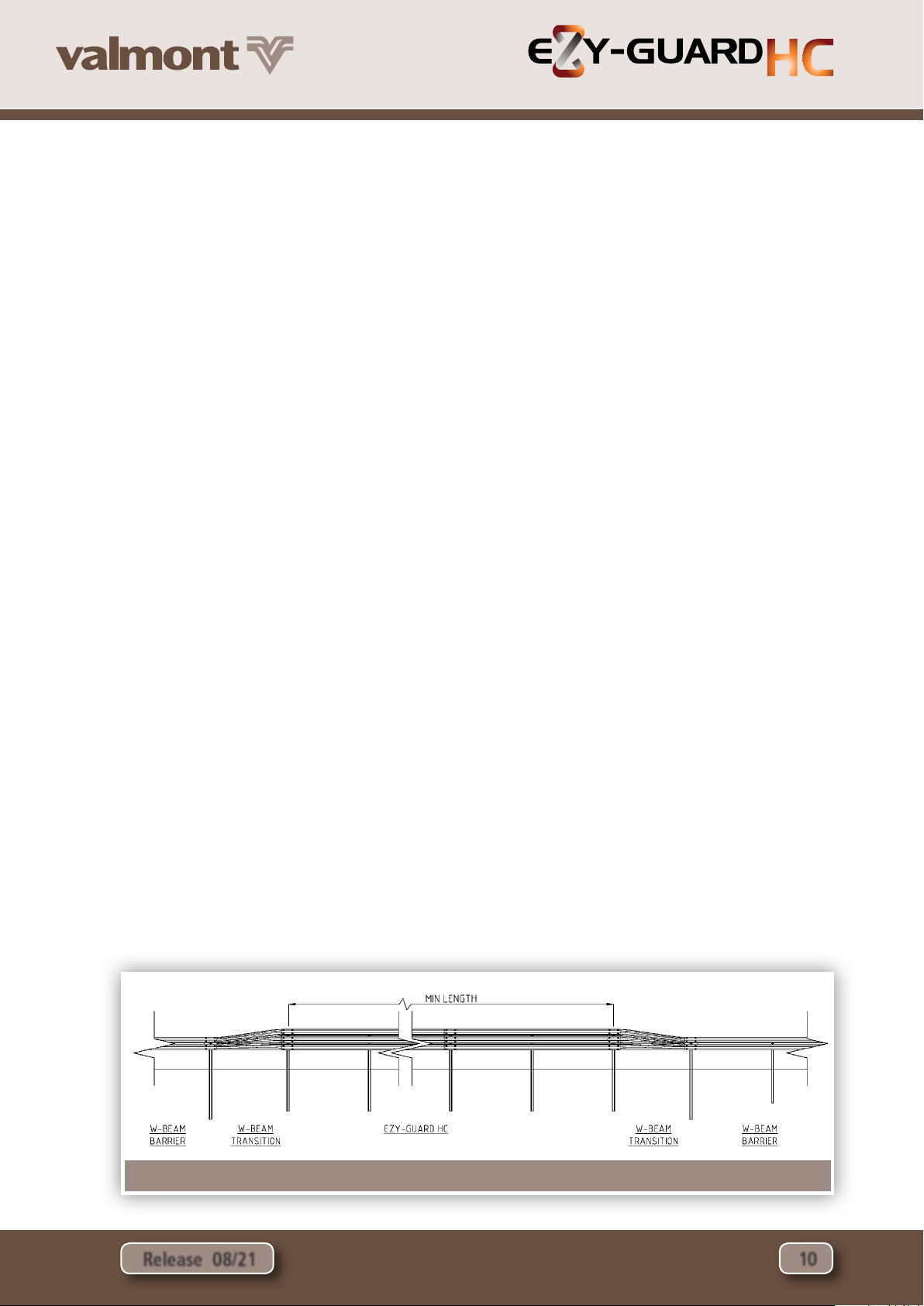
For instances where geometric constraints limit the
installation of the recommended length under the above
design methods, the absolute minimum length of minimum
length of need for Ezy-Guard HC is dependent on the design
containment level. For measurement of minimum installed
length, refer Figure 6 below.
• MASH Test Level 3 containment, where the design vehicle
is a 2,270kg pick-up, the minimum length of Ezy-Guard
HC is 20m.
• MASH Test Level 4 containment, where the design vehicle
is a 10,000kg truck, the minimum length of Ezy-Guard HC
is 26m.
7.3 Sequence of Work
Where Ezy-Guard HC is being constructed on a road open
to traffic, it is recommended that the work commence at the
end closest to the approaching traffic. Leading terminals and
transitions shall be commissioned at the earliest practical time.
7.4 Modifications
Ezy-Guard HC shall be constructed in the configuration
as detailed in Valmont Highway’s drawings. This is the
configuration in which the system has been crash tested. No
modifications shall be made to the system unless verified by
Valmont Highway.
Flame cutting of rails or posts is not permitted. Saw cutting
and drilling is permitted in the event that a post is to be
installed at an irregular spacing and/or rock is encountered
and the post embedment depth has been modified.
Any modification carried out after fabrication will require
repair to the galvanized coating. This is undertaken by
applying two coats of an organic zinc rich epoxy paint
complying with AS/NZS 3750.9. This is to be applied to the
repair areas in two coats. Each coat shall have a minimum
dry film thickness of 50 μm.
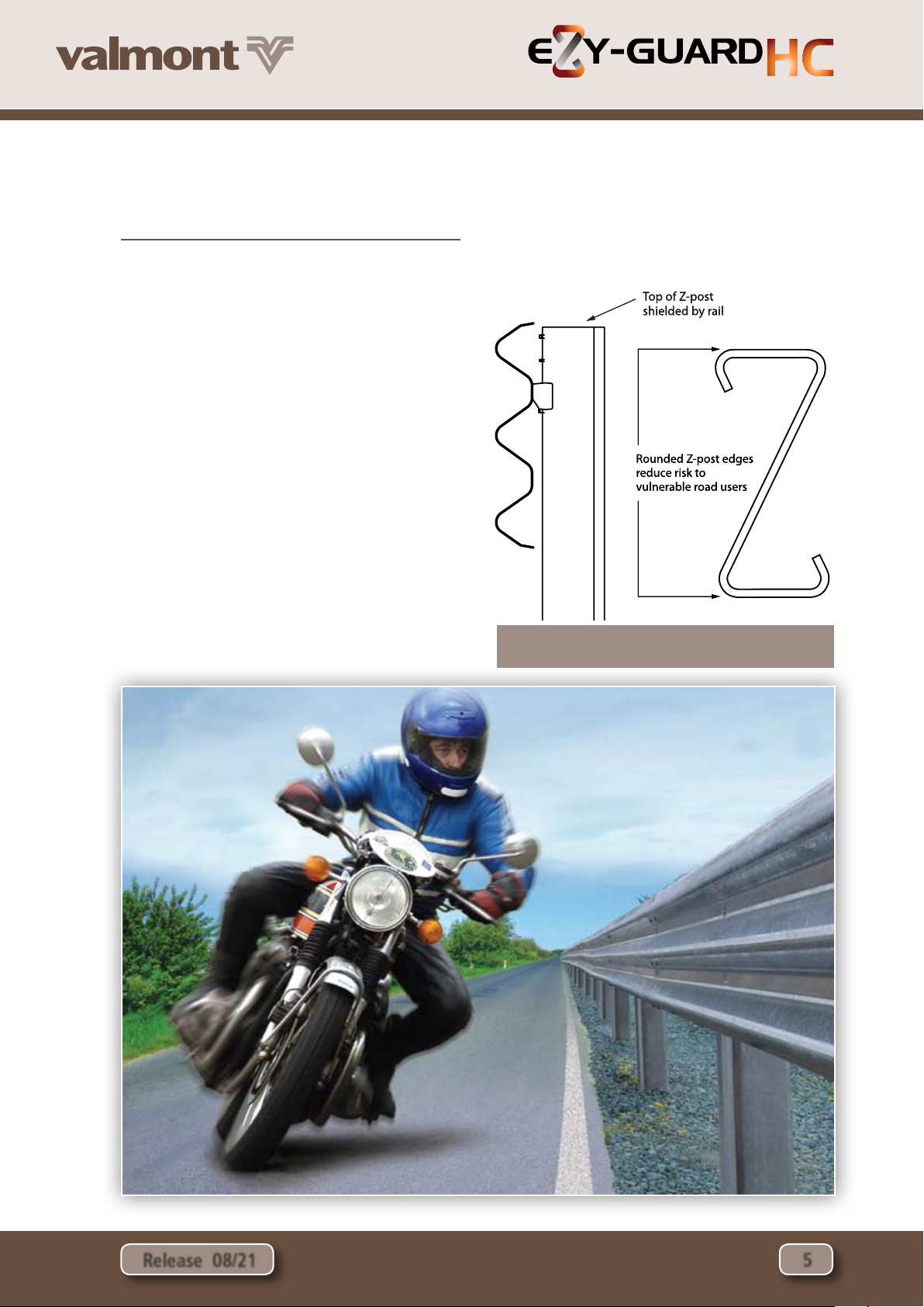
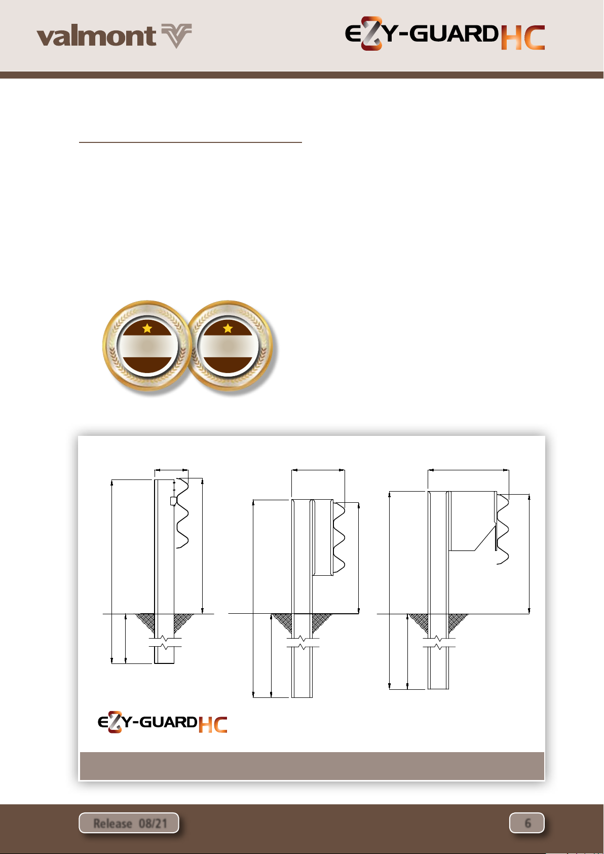
7.5 Soil Requirements & Embedment Depth
The Z-post is designed to yield by bending near ground level
during impact. Provided the post is embedded in material
that allows this failure mechanism to be replicated, the Ezy-
Guard HC functionality will be retained. The Z-posts will
provide lateral resistance until the impacting vehicle causes
deformation of the posts. At this point the Ezy-HC-Carriages
will provide a controlled release of the rail from the Z-posts
resulting in safe vehicle containment and redirection.
7.5.1 Standard Soil
Ezy-Guard HC has been evaluated for installation in standard
soil in accordance with AASHTO standard specifications for
‘Materials for Aggregate and Soil Aggregate Subbase, Base
and Surface Courses,’ designation M 147.
Change to:
When installed in weak soil, the 1,030mm embedment depth
of the Z-post is sucient for installation up to 500mm of the
rounding point on 2:1 embankment slopes. If installation
is required within 500mm of the rounding point, the post
embedment depth is required to be increased to 1,350mm.
A longer Z-post is available from Ingal Civil for these
applications.
For a TL4 containment level, installations within 1.7m from
the hinge point should be considered within the requirements
of the road controlling authority Extended Design Domain
requirements.
Figure 6. Minimum length measurement

Release 08/21
High-Containment Roadside Safety Barrier
11
HIGHWAY
1kN Force
700mm
Embedded Z-Post
Ground Level
Displacement
less than 1mm
1
kN F
o
r
ce
700
mm
E
m
bedded
Z-P
ost
G
round Leve
l
Disp
l
acemen
t
l
ess
t
h
a
n 1mm
7.6 Post Pullover Test
In the event that the soil type cannot be verified, the
suitability of the post foundation can be established through
a post pullover test.
This is undertaken by applying a 1kN load to the post,
700mm above ground level. The load is applied prior to the
attachment of the rail. Displacement at the base of the post
shall not exceed 1mm whilst the load is applied.
An alternative post pull over test can be achieved via a
more destructive means, whereby a load of 1.2 tonnes is
applied to the test post at a height of 700mm. This loading
approximates the probable capacity of the post and should
be able to be maintained with minimal rotation of the post
in the soil. At the completion of the testing the post should
be removed from the test location and should not be used in
the installation.
7.7 Posts on Base Plates
In the event that the Z-post cannot be installed to the required
in-ground depth, the use of a base plate mounted on a suitable
foundation can be adopted. Posts on base plates are typically
used at culvert locations, and in areas where underground
services restrict posts from being driven into the ground.
Refer to Valmont Highway drawings for the installation of
posts on base plates base plates and to your local Valmont
representative for appropriate footing design conditions.
7.8 Z-Posts in Rock
Traditional guardrail posts are designed to yield in the
surrounding soil and their placement in rock or concrete is
problematic. Restraining the traditional posts by setting them
in narrow holes drilled into rock, setting them in concrete or
placing a mowing strip around the posts can lead to a failure
of the system to safely contain and redirect the errant vehicle.
The specially engineered Z-post dissipates energy by yielding
through bending near ground level. This means that typical
recommendations for the installation of a traditional guardrail
post in rock are not applicable to the Z-post. When rock is
encountered, the installation guidelines as detailed in Table
5 are applied. If required the bottom of the post may be cut
onsite by a disc grinder or equivalent steel cutting tool. A
corrosion resistant treatment will need to be applied to the
freshly cut surface,Valmont recommend a Zinc metal spray in
accordance with section 7.4.
7.9 Non-Standard Post Spacing
Occasionally, an underground services or obstruction may
prevent a post from being installed at the recommended
spacing. In these instances, there are a number of options:
• Ommit the post and leave a 4m gap. This will result in an
11% increase in deection if impacted in that location. For
bidirectional trac, this increase in deection is applicable
for 4m upstream and downstream of the omitted post. A
single post omission is permissible for no more than one
location in 30m of Ezy-Guard HC.
• If the underground conict is short in length, the post can
be moved 1m upstream or downstream from the original
position. Special rails are available from Ingal with slots
at 1m intervals.Alternatively, the rail can be drilled to take
the M16 carriage bolt. The drilled hole should have the
galvanized coating repaired in accordance with section
7.4.
• A concrete foundation can be installed and a post on
baseplate can be anchored to the foundation. Refer
section 7.7 for further details.
7.10 Delineation
A specially designed delineator is attached to the Z-post.
Typically, delineation is arranged so that drivers approaching
from either direction will see only;
•Red retro-reflectors on their left;
•White retro-reflectors on their right
on two-way carriageways; and
•Yellow retro-reflectors on their
right on one-way carriageways and
medians separating traffic in opposing
directions
The spacing of delineators is dependant
upon driver line of sight.As a general rule
delineators are provided for installation
every 20m on straight alignments.
Installation on curves will require a
closer spacing dependant upon the
radius of the roadway.
Figure 7: Z-Post Pullover Test

Release 08/21
High-Containment Roadside Safety Barrier
12
HIGHWAY
Site Condition Installation Requirements
Rock is
encountered at
the surface.
Drill a 160-300mm diameter
hole to a depth of 500mm,
install the post in the hole and
backfill.
Rock is
encountered
within 450mm of
the surface.
Drill a 160-300mm diameter
hole 500mm into the rock
or to a minimum total post
embedment depth of 700mm,
whichever comes first, install the
post and backfill.
Table 2: Installation of Ezy-Guard HC Z-Posts in Rock
rock
500
500
700 min.
0-450
rock
soil

Release 08/21
High-Containment Roadside Safety Barrier
13
HIGHWAY
Site Condition Installation Requirements
Rock is
encountered
450mm to
650mm below
ground.
Drill a 160-300mm diameter
hole 250mm into the rock
or to a minimum total post
embedment depth of 700mm,
whichever comes first, install the
post and backfill.
Rock is
encountered
650mm to
1000mm below
ground.
Drill a 160-300mm diameter
hole 50mm into the rock
or to a minimum total post
embedment depth of
1000mm, whichever comes
first, and install the post and
backfill.
250
700 min.
0-700
rock
soil
50
1000 min.
650 – 1000
rock
soil

Release 08/21
High-Containment Roadside Safety Barrier
14
HIGHWAY
Figure 8: Curvature Measurements
Figure 9: Curvature Orientation
Table 3: Rail Curvature Values
Radius (m) Ø Degrees C (mm) H (mm)
2.4 95 3553 786
3 76 3710 642
4 57 3835 490
5 45 3894 395
6 28 3926 330
7 33 3946 284
8 29 3958 249
9 26 3967 221
10 23 3973 199
12 19 3982 166
14 16 3986 143
16 15 3990 125
20 12 3993 100
24 10 3995 83
28 8 3997 71
32 7 3997 62
35 7 3998 57
40 5 3998 50
45 5 3999 44
7.11 Curving of Rails
Guardrail used for the assembly of Ezy-Guard HC may be
shop curved to fit any radius from 2.4m to 45m Convex.
Ezy-Guard HC for Concave Curves can be used from 2.4m to
45m. Curves in excess of 45m do not require shop curving as
the rail can be field installed to suit. Guardrail may be curved
either concave or convex to the traffic face and can be part-
curved along its length to suit site requirements.
7.11.1 Measuring Curvature
1. Mark along the arc of the curve at 4m intervals.
2. Measure the corresponding chord length (C)
- refer to Figure 8.
3. Measure the corresponding centre offset (H)
- refer to Figure 8.
4. Use the values for C & H to select the radius
from Table 3.
5. Determine the curvature orientation from Figure 9.
7.11.2 Identification of Curved Rails
Where a rail has been factory curved by Ingal, the radius of
curvature is marked on the rear face of the rail.

Release 08/21
High-Containment Roadside Safety Barrier
15
HIGHWAY
7.12 Installation Sequence
The following written instructions should be read in
conjunction with Valmont Highway’s drawings.
A generic Safe Work Method Statement is available from
Valmont Highway to assist in the safe installation of Ezy-
Guard HC.
Only items purchased from Valmont Highway shall be used
for the construction of Ezy-Guard HC.
1. Ensure the area has been inspected for underground
hazards and that suitable traffic control is in place.
2. Post locations are marked ensuring any fixed object
hazard to be protected is located outside the expected
dynamic deflection of the barrier.
3. The post in relation to the direction of traffic is orientated
as per Figure 10 and 11.
4. Posts are driven directly into the ground and should
be vertical. The post installation process shall not
cause damage to the post, such that it reduces the
effective operation of the safety barrier or its design
life, or introduces sharp tearing edges, nor shall it cause
damage to pavement. If the Ezy-HC-Carriage cannot
freely move as it is attached to the post as a result
of deformation of the post during installation, then
the post shall be replaced. The use of a vibrating post
hammer will reduce deformation to the top of the post
and install the post at a controlled rate.
5. Alternate to driving the posts, a minimum 200-300mm
hole can be augured and the post placed in the hole.
The posthole is then backfilled with the material that
was excavated. If installing in soil, the material should
be placed in layers of 150mm and suitably compacted to
not less than the density of the surrounding layers.
6. Posts are spaced at 2m – 1,905mm spacings are required
on transitions to w-beam - and reduced spacings are
required where requested by engineer.
7. The height of the Z-post above ground level is 970mm.
8. The Ezy-HC-Carriage is attached to the face of the post.
The Ezy-HC-Carriage will come to rest on the positioning
lug fabricated on the Z-post.
Figure 10: Z-Post Orientation
Figure 11: Ezy-Carriage Orientation
Figure 12: Attachment of Carriage to Z-Post
TRAFFIC FLOW
Carriage resting
on lugs
TRAFFIC FLOW

Release 08/21
High-Containment Roadside Safety Barrier
16
HIGHWAY
9. Rails are attached to the Ezy-HC-Carriage using the
M16x30mm carriage bolts.The post bolts are identified
by the socket recess located in the head of the bolt.
The bolts are tightened to snug tight using a 10mm
hex. key.
10. Rails are spliced together at every second post using
M16x32mm mushroom head bolts and oversized nuts.
There are 12 bolts required per splice connection. A
pinch bar may be used to assist in the alignment of
splice holes. The use of a driving pin to elongate the
slots is NOT to be used since this may cause tearing of
the rail at the slot location. The bolts are tightened to
snug tight.
11. Rails are orientated so that no leading edge is
presented to the traffic face as shown in Figure 15.
12. It is recommended that posts be installed only a few
metres ahead of rail assembly to ensure correct post
spacing and alignment. On curves, the rails can be used
as a template and laid on the ground to determine
post locations.
13. The construction of Ezy-Guard HC shall form a smooth
line vertically and horizontally when viewed along
the line of the system, free from humps, sags or other
irregularities.
14. The Ezy-Guard HC components are to be free from splits,
burrs or sharp edges after installation.Any minor damage
is to be repaired in accordance with section 7.4.
15. Any disturbed pavement or material around a post
shall be left dense, tight, and smooth so that resistance
to water penetration is similar to that of the adjacent
surface.
7.13 Installation Tolerances
•The tolerance on height of the barrier shall be plus or
minus 20mm.
•The tolerance for the line of the barrier shall be plus or
minus 20mm in plan view.
•The tolerance for departure from the upright axis shall be
plus or minus 15mm at the top of the barrier.
•The tolerance on post spacing shall be plus or minus 25mm.
8.0 mAIntenAnce
It is recommended that annual inspections be performed to
ensure the following;
•The system is appropriately delineated;
•Debris has not accumulated around the system that may
impede the performance of the barrier or the trajectory of
an impacting vehicle;
•The system is suitably anchored with appropriate
terminals and/or transitions. If the system is anchored with
terminals, the cable assembly shall be taut and tensioned
to its recommended value; and
•All splice bolts and post bolts are snug tight.
9.0 product StorAGe
All posts and rails are hot dip galvanized in accordance
with AS/NZS 4680. It is important that stored galvanized
work is stacked so that each item is well ventilated and can
adequately drain rainwater from its surfaces.
Poor storage can give rise to wet storage stain (white rust)
which is caused by water (rain or condensation) in badly
drained or ventilated conditions. This can occur very quickly,
particularly in warm, humid conditions.
Figure 13: Carriage Bolt
Figure 14: Splice Bolt & Nut
Figure 15: Orientation of Rail Lap
TRAFFIC DIRECTION

Release 08/21
High-Containment Roadside Safety Barrier
17
HIGHWAY
Figure 16: Ezy-Guard HC Installation Tolerances
Plan View Side View Front View
± 20mm± 20mm
Height ± 20mm
± 25mm post
spacing tolerance
measured at top
of post
± 20mm lateral
tolerance from
design position
of rail

Release 08/21
High-Containment Roadside Safety Barrier
18
HIGHWAY
Ezy-Guard HC Installation Checklist
Customer:
Project:
Barrier ID:
Barrier Length:
Checked By:
Signed:
Date
Have the Z-posts been positioned every 2m Yes No
Carriages are positioned on the posts between the retaining lugs and the resistance tabs Yes No
Posts are installed to the correct height (970mm) and within the tolerances of section 7.13 Yes No
Have the Ezy-HC-Carriages been correctly orientated Yes No
Have the rails been attached to the Ezy-HC-Carriages using the appropriate carriage bolt Yes No
Have the rails been spliced observing the correct lap Yes No
Have the rails been spliced with M16x32mm mushroom head bolts Yes No
Are all splice bolts and post bolts snug tight Yes No
Is the Ezy-Guard HC attached to suitable transition rails then anchored with approved terminals Yes No
Are the cables in the terminals tensioned to their nominated torque (taut) Yes No
Has any minor damage been repaired using two coats of an organic zinc rich paint Yes No
Does the barrier form a smooth line vertically and horizontally when viewed along the system Yes No
Is the barrier system free from humps, sags or other irregularities Yes No
Has the ground or pavement around the post been left dense, tight and smooth Yes No
Are the barrier components free from splits, burrs or sharp edges after installation Yes No
Disclaimer:
Important Note:The conformity of the installation is the responsibility of the installation contractor, and Valmont Highway accepts no liability for or in connection
with any installation that is outside of the specifications of this manual or the Road Controlling Authority. For more information, please refer to our Standard
Terms and Conditions of Sale available on our website: www.ingalcivil.com.au.

Release 08/21
High-Containment Roadside Safety Barrier
19
HIGHWAY
Table 4: Damage Assessment of Ezy-Guard HC
Type of Defect Description of the Defect Action to be Taken
Galvanizing
damage on Z-Posts.
The sum total of the damaged area does not exceed 35cm2
(0.5% of the total surface area).
The sum total of the damaged area exceeds 35cm2
An organic zinc rich epoxy paint is to be applied to the
repair area in two coats as per section 7.4.
The Z-post is to be replaced.
Galvanizing
damage on rails.
The sum total of the damaged area does not exceed 200cm2
(0.5% of the total surface area) and no individual damaged
area does not exceed 40cm2.
The sum total of the damaged area exceeds 200cm2(0.5%
of the total surface area) and/or an individual damaged area
exceeds 40cm2.
An organic zinc rich epoxy paint is to be applied to the
repair area in two coats as per section 7.4.
The rail is to be replaced.
Mechanical
damage on
Ezy-HC-Carriages.
The Ezy-HC-Carriage has chips or cracks. The Ezy-HC-Carriage is to be replaced.
Mechanical
damage on Z-Posts.
The post is bent.
The Ezy-Carriage cannot travel freely along the post due to
distortion.
The post is to be replaced.
Mechanical
damage on rail.
The rail is dented, twisted or flattened.
There are tears in any part of the rail.
The slots in the rail are distorted.
The rail is to be replaced.
Mechanical
damage on bolts.
The body of the bolt is distorted.
The thread of the bolt is damaged.
The bolt is to be replaced.
Disturbance of
material around
posts
The material around the post is loose or uncompacted. Any disturbed pavement or material around a post shall
be left dense, tight and smooth so that resistance to water
penetration is similar to that of the adjacent surface.
10.0 repAIr
10.1 Bush Fire Damage
Ezy-Guard HC does not contain any plastic, timber or rubber
components that will burn.
The performance of galvanised coatings when subjected to
fires depends upon a number of factors, such as flame duration
and intensity.
Typical bushfire conditions may expose steel structures to an
air temperature of 800°C for periods of up to 120 seconds,
however zinc coatings are generally reflective and will not
absorb heat at the same rate as an uncoated steel surface.
Depending on the section thickness of the steel, the actual
steel surface temperature may not exceed 350°C.
Typically, the bushfire flame duration and intensity are
not high enough to compromise the structural strength of
the steel. The hot dip galvanized coating will also typically
remain unaffected through a bushfire event. If the bushfire
causes damage to the galvanized surface, then the item(s)
shall be replaced.
10.2 Damage Assessment
In the event of a vehicle impact, damage to the barrier is to
be assessed in accordance with Table 4.
A Safe Work Method Statement is available from Valmont
Highway upon request to assist in the safe repair of Ezy-
Guard HC.
Any item that is replaced is to be reinstated observing the
installation tolerances nominated in Section 7.13. Only items
purchased from Valmont Highway shall be used for the repair
of Ezy-Guard HC.
10.3 Dismantling Sequence
Prior to undertaking dismantling due to a vehicle impact,
the area should be assessed for hazards. These include trip
hazards, sharp edges and snag points.
During a vehicle impact, the rail will disengage from the posts
as they yield by bending at ground level. The recommended
dismantling sequence is as follows;
1. Dismantle the rail splice by removing the M16x32mm
mushroom head bolts and nuts.There are 8 bolts located
at each splice location.
2. Rails that are still attached to posts outside the impact
area are disconnected by removing the carriage bolts. A
10mm hex key is required.
3. Once the area is clear of damaged rail, the posts can be
removed. Since the posts yield by bending near ground
level, a sling or chain can be attached below the bent
section.
4. The damaged post can be lifted using a backhoe or post
extractor attachment.
5. Any disturbed pavement material shall be left dense, tight,
and smooth prior to the installation of replacement posts.
6. Rails, posts and carriages to be disposed of, should be
recycled at a ferrous scrap recycling facility.

Release 08/21 20
HIGHWAY
Table of contents
Other valmont Safety Equipment manuals