SEA USA USER 1 24V DG R1 User manual
USER 1 - 24V DG R1
24V ELECTRONIC CONTROL UNIT FOR SLIDING GATES AND BARRIERS
67411535 REV 07 - 06/2014
International registered trademark n. 2.777.971
SEA USA Inc.
10850 N.W. 21st unit 160 DORAL MIAMI
Florida (FL) 33172 USA
Tel. -
Toll free:
:++1-305.594.1151 ++1-305.594.7325
800.689.4716
web site: www.sea-usa.com
e-mail: [email protected]

Details
General
An appliance shall be provided with an instruction manual. The instruction manual shall give instructions for the installation,
operation, and user maintenance of the appliance.
The installation instructions shall specify the need for a grounding-type receptacle for connection to the supply and shall stress the
importance of proper grounding.
The installation instructions shall inform the installer that permanent wiring is to be employed as required by local codes, and
instructions for conversion to permanent wiring shall be supplied.
Information shall be supplied with a gate operator for:
a) The required installation and adjustment of all devices and systems to effect the primary and secondary protection against
entrapment (where included with the operator).
b) The intended connections for all devices and systems to effect the primary and secondary protection against entrapment. The
information shall be supplied in the instruction manual, wiring diagrams, separate instructions, or the equivalent.
Vehicular gate operators (or systems)
A vehicular gate operator shall be provided with the information in the instruction manual that defines the different vehicular gate
operator Class categories and give examples of each usage. The manual shall also indicate the use for which the particular unit is
intended as defined in Glossary, Section 3. The installation instructions for vehicular gate operators shall include information on
the Types of gate for which the gate operator is intended.
A gate operator shall be provided with the specific instructions describing all user adjustments required for proper operation of the
gate. Detailed instructions shall be provided regarding user adjustment of any clutch or pressure relief adjustments provided. The
instructions shall also indicate the need for periodic checking and adjustment by a qualified technician of the control mechanism
for force, speed, and sensitivity.
Instructions for the installation, adjustment, and wiring of external controls and devices serving as required protection against
entrapment shall be provided with the operator when such controls are shipped with the operator.
Instructions regarding intended installation of the gate operator shall be supplied as part of the installation instructions or as a
separate document. The following instructions or the equivalent shall be supplied where applicable:
a) Install the gate operator only when:
1) The operator is appropriate for the construction of the gate and the usage Class of the gate,
2) All openings of a horizontal slide gate are guarded or screened from the bottom of the gate to a minimum of 4 feet (1.22
m) above the ground to prevent a 2-1/4 inch (57.2 mm) diameter sphere from passing through the openings anywhere in
the gate, and in that portion of the adjacent fence that the gate covers in the open position,
3)All exposed pinch points are eliminated or guarded, and
4) Guarding is supplied for exposed rollers.
b) The operator is intended for installation only on gates used for vehicles. Pedestrians must be supplied with a separate access
opening. The pedestrian access opening shall be designed to promote pedestrian usage. Locate the gate such that persons will
not come in contact with the vehicular gate during the entire path of travel of the vehicular gate.
c) The gate must be installed in a location so that enough clearance is supplied between the gate and adjacent structures when
opening and closing to reduce the risk of entrapment. Swinging gates shall not open into public access areas.
d) The gate must be properly installed and work freely in both directions prior to the installation of the gate operator. Do not over-
tighten the operator clutch or pressure relief valve to compensate for a damaged gate.
e) (not applicable)
f) Controls intended for user activation must be located at least six feet (6’) away from any moving part of the gate and where the
user is prevented from reaching over, under, around or through the gate to operate the controls. Outdoor or easily accessible
controls shall have a security feature to prevent unauthorized use.
USER 1 - 24V DG R1
International registered trademark n. 2.777.971
267411535 REV 07 - 06/2014

g) The Stop and/or Reset button must be located in the line-of-sight of the gate. Activation of the reset control shall not cause the
operator to start.
h)Aminimum of two (2) WARNING SIGNS shall be installed, one on each side of the gate where easily visible.
i) For gate operators utilizing a non-contact sensor:
1) See instructions on the placement of non-contact sensors for each Type of application,
2) Care shall be exercised to reduce the risk of nuisance tripping, such as when a vehicle, trips the sensor while the gate is
still moving, and
3) One or more non-contact sensors shall be located where the risk of entrapment or obstruction exists, such as the
perimeter reachable by a moving gate or barrier.
j) For a gate operator utilizing a contact sensor:
1) One or more contact sensors shall be located where the risk of entrapment or obstruction exists, such as at the leading
edge, trailing edge, and postmounted both inside and outside of a vehicular horizontal slide gate.
2) One or more contact sensors shall be located at the bottom edge of a vehicular vertical lift gate.
3) One or more contact sensors shall be located at the pinch point of a vehicular vertical pivot gate.
4) Ahardwired contact sensor shall be located and its wiring arranged so that the communication between the sensor and
the gate operator is not subjected to mechanical damage.
5) A wireless contact sensor such as one that transmits radio frequency (RF) signals to the gate operator for entrapment
protection functions shall be located where the transmission of the signals are not obstructed or impeded by building
structures, natural landscaping or similar obstruction. A wireless contact sensor shall function under the intended end-
use conditions.
6) One or more contact sensors shall be located on the inside and outside leading edge of a swing gate.Additionally, if the
bottom edge of a swing gate is greater than 6 inches (152 mm) above the ground at any point in its arc of travel, one or
more contact sensors shall be located on the bottom edge.
7) One or more contact sensors shall be located at the bottom edge of a vertical barrier (arm).
Revised 56.8.4 effective February 21, 2008
Instruction regarding intended operation of the gate operator shall be provided as part of the user instructions or as a separate
document. The following instructions or the equivalent shall be provided:
IMPORTANT SAFETY INSTRUCTIONS
WARNING – To reduce the risk of injury or death:
ATTENTION: pour réduire le risque de dommages ou mort:
1. READAND FOLLOW ALL INSTRUCTIONS.
2. Never let children operate or play with gate controls. Keep the remote control away from children.
3.Always keep people and objects away from the gate. NO ONE SHOULD CROSS THE PATH OF THE MOVING GATE.
4. Test the gate operator monthly. The gate MUST reverse on contact with a rigid object or stop when an object activates the non-
contact sensors. After adjusting the force or the limit of travel, retest the gate operator. Failure to adjust and retest the gate
operator properly can increase the risk of injury or death.
5. Use the emergency release only when the gate is not moving.
6. KEEP GATES PROPERLY MAINTAINED. Read the owner’s manual. Have a qualified service person make repairs to gate
hardware.
7. The entrance is for vehicles only. Pedestrians must use separate entrance.
8. SAVE THESE INSTRUCTIONS.
International registered trademark n. 2.777.971
3
USER 1 - 24V DG R1
67411535 REV 07 - 06/2014

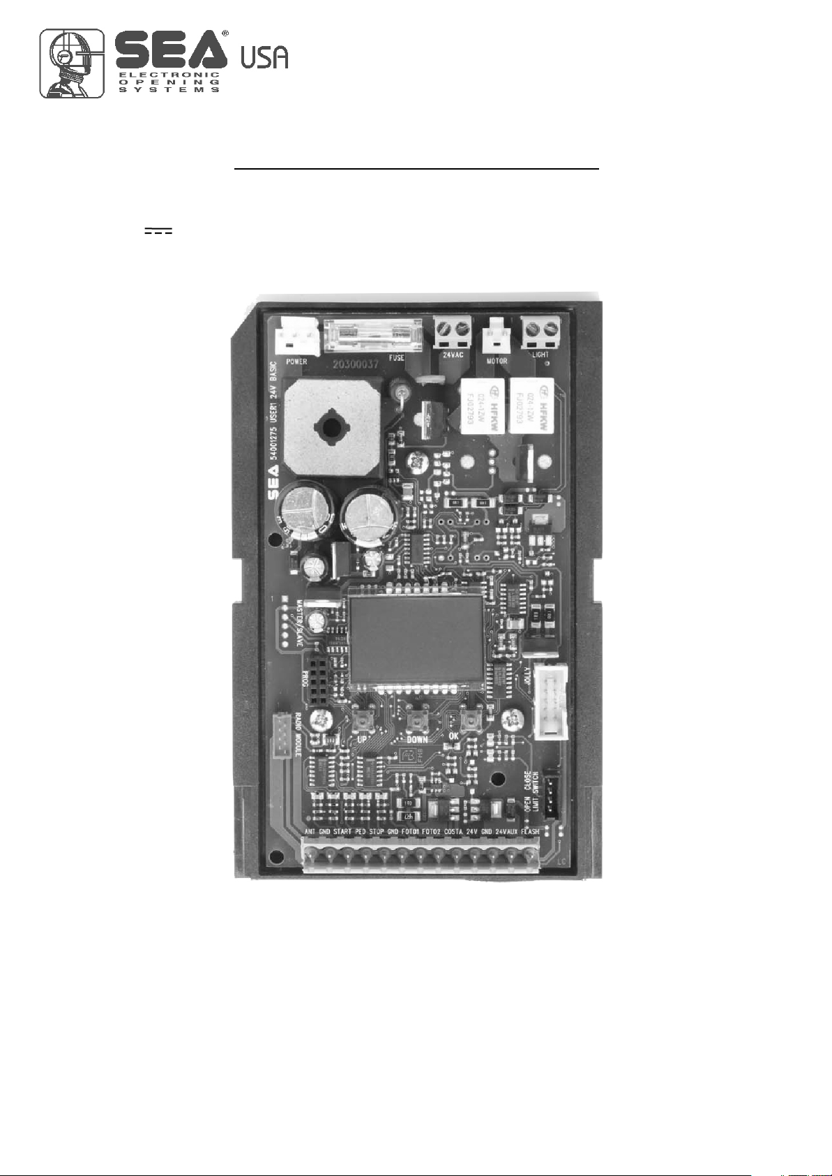
DESCRIPTION OF THE COMPONENTS
CN1 = Input/Output connector
CN2 = Limit switch connector
CN3 = Jolly-Jolly 2 connector
CN4 = Master/slave connector
CN5 = Courtesy light output plug
CN6 = Motors connector
CN7 = Batteries connector
CN8 = Power connector
CNA = RX Receiver connector
CNP = Programming connector
EXP = External module connector
OK = Programming button
DOWN = Programming button
UP = Programming button
RD1 =Motors piloting Mosfet
RD3 = Motors piloting Mosfet
R1 = Motors command relay
R2 = Motors command relay
PR1 = Rectifier jumper
F1 = Fuse 10 AT
CN8 F1
CN1
CNA
CN3
CN5
CNP
CN6
RL2
RL1
CN2
CN4
CN7
UP DOWN OK
RD3
RD1
PR1
DISPLAY
1 2 3 4 5 6 7 8 9 10 11 12 13
1
EXP
POWER FUSE BATTERY
- S +
MOTOR LIGHT
MASTER/SLAVE
PROG
RADIO MODULE
JOLLY
LIMIT SWITCH
156 mm (6 inches)
100 mm (4 inches)
RECEIVER RX
JOLLY-JOLLY2
TECHNICAL SPECIFICATIONS
Control unit power supply
Absorption in stand by
Environment temperature
Specifications of external enclosure
:
:
: -20 +55 (
:
24 V~
30 mA
-4°F +122°F)
305 x 225 x 125 mm (12 x 9 x 5 inches) - Ip55
International registered trademark n. 2.777.971
USER 1 - 24V DG R1
67411535 REV 07 - 06/2014
4

International registered trademark n. 2.777.971
USER 1 - 24V DG R1
CONNECTIONS
LIGHT (CN5)
Max 100mA
POWER (CN8)
24V~
MOTOR (CN6)
M
Max 200W
JUMPERS
123 4 5 6 7 8 910 11 12 13
CN1
Start
Stop
Common
Antenna
START Ped.
Common
Photocell 1
Common
ANT COM START
PEDST
STOP COM PH1 PH2
EDGE
AUX
COM 24V (FL)-
AUX
(24V 200 mA max)
24V 750 mA max
(Accessori)
Safety edge
The herein reported functions
are available starting from
revision 34.
Flash (-)
Photocell 2
+ +
- -
123 4 5 6 7 8 910 11 12 13
CN1
ANT COM START
PEDST
STOP COM PH1 PH2
EDGE
AUX
COM 24V (FL)-
Start
Stop
Common
Antenna
START Ped.
Common
Photocell 1
Common
AUX
(24V 200 mA max)
24V 750 mA max
(Accessori)
Safety edge
Flash (-)
Photocell 2
+ +
- -
Optional
WARNING: The control unit is designed with the automatic detection of not used N.C. inputs (photocells, Stop and Limit switch) except the
SAFETY EDGE input. The exclude inputs in self-programming can be restored in the “Check inputs” menu without need to repeat the
programming (pag.13).
Obligatory jumper without accessory connection.
67411535 REV 07 - 06/2014 5

International registered trademark n. 2.777.971
USER 1 - 24V DG R1
UPDOWN
QUICK START
MENU
SEA
SET
MENU
SEA
SET
MENU
SEA
SET
MENU
SEA
SET
MENU
SEA
SET
MENU
SEA
SET
MENU
SEA
SET
MENU
SEA
SET
MENU
SEA
SET
MENU
SEA
SET
MENU
SEA
SET
OK
2
3
4
5
6
7
8
OK
OK OK
OK OK
OK OK
OK OK
OK OK
OK OK
UP
UP
UP
UP
UP
UP
UP
PRESS
BUTTON STORED
TRANSMITTERS
START
MOTOR
REVERSE
MOTOR
LOGIC
PAUSE TIME
START IN
PAUSE
PROGRAM-
MING
TEST START
PROGRAMMING
BUTTONS
OK
DOWNUP
9
Skip this step if you do not want to program a transmitter
Press the
button of the
TX to be
stored
OK to exit
Menu or press
the button of
the next TX to
be stored
OKOK Choose the type of
motor with
UP or DOWN
To confirm and return
to main menu
Choose "ON" with UP or
DOWN button only if in
programming the motor starts
in opening
Return to menu 7,
place the gate halfway
and repeat
the times programming
With UP or DOWN
choose
the desired logic
To confirm and return
to main menu
With UP or DOWN
choose a delay for
automatic closing
To confirm and return
to main menu
Skip this step
if you wna tto work
in half-automatic
logic
With UP or DOWN
Choose ON
To confirm and return
to main menu
With UP or DOWN choose ON
to start times learning
At the end of the selflearning
the control unit returns automatically
to the main menu
With
UP or DOWN Choose
ON to start test
To confirm and return to
main menu
Skip this step if a TX has already been stored
1
MENU
SEA
SET
MENU
SEA
SET
OK
UP
LANGUAGE ITALIANO
UP
ALL OTHER PARAMETERS HAVE DEFAULT SETTINGS WHICH ARE USEFUL FOR THE 90% OF THE APPLICATIONS
BUT CAN BE HOWEVER SET THROUGH THE SPECIAL MENU. FOR ENTERING INTO THE SPECIAL MENU MOVE
ON ONE OF THE MENU AND PRESS THE UP AND DOWN BUTTONS AT THE SAME TIME FOR 5 S.
PROGRAMMING
MENU
SEA
SET
(See
page 7)
(See
page 7)
If the motor has
magnetic limit switches,
select "Magnetic"
in the special menu:
34-Limit switch type
RECEIVER
MISSING
If on the display
appears the item:
Check if a receiver has
been connceted
(see page 4)
The gate will execute a CLOSING-OPENING-CLOSING CYCLE
67411535 REV 07 - 06/2014
6
7
International registered trademark n. 2.777.971
USER 1 - 24V DG R1
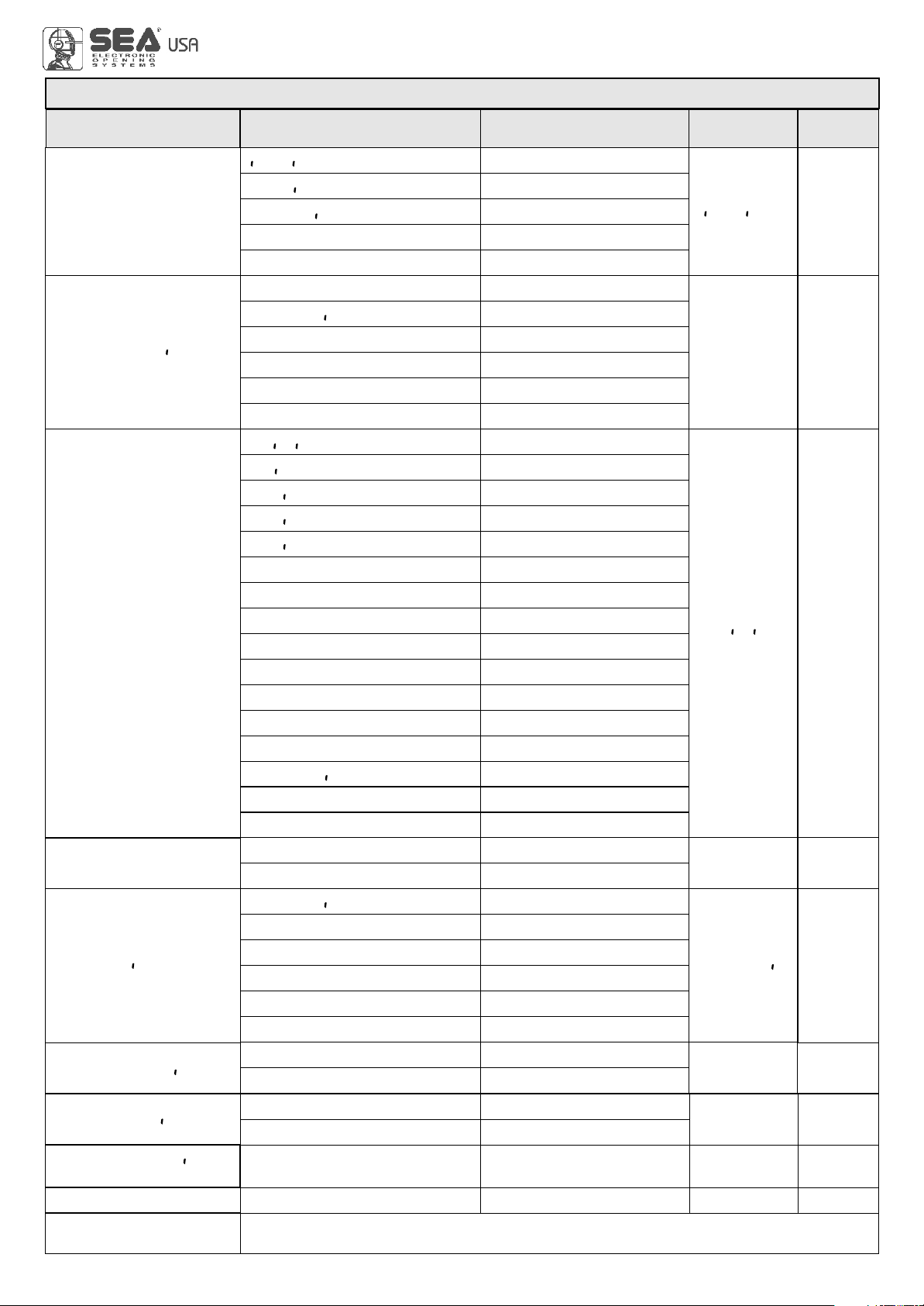
MENU Default
1 - langvage
SET
espanol
engl sk
fran(a s
tal ano
stop
start
Erg ax
U
Erg
uerg
off
on
off
1,2,3
Italian
English
French
Spanish
Start
Stop
External module
Joint
Sprint 3 meters
Sprint 4 meters
Sprint 5 meters
Storm 5 meters
Storm 6 meters
Storm 7 and 7.5 meters
Saturn
Mercury 800
VergL.5 meters
VergL.4 meters
VergL.3 meters
Erg Maxi
Verg
Erg
start
Ped Start.
off
Avto at (
U
off
tal ano
MENU FUNCTIONS TABLE USER1 24V DG R1
Description Set value
U
2 - trans tters
(Lear e ory
UU
External odvle
U
Pedestr an Start
Delete a trans itter
U
3 - otor
U
Jo nt
Spr nt 3 eters
U
Spr nt 4 eters
U
Spr nt 5 eters
U
Stor 5 eters
U
U
Stor 6 eters
U
U
Stor 7.5 eters
U
U
satvrn
Er(vry 800
U
Uergl.5 eters
U
Uergl.4 eters
U
Uergl.3 eters
U
Sl d ng
Sl d ng
U
4 - reuerse otor
5 - log (
Avto at (
U
open-stop-(lose-stop-open
2 bvttons
safety
Dead an
U
open-stop-(lose-open
6 - paVse t e
U
Pedestrian Start
Delete single transmitter
Sliding
Synchronized right motor
Synchronized left motor
Automatic
Step by step type 1
Step by step type 2
Two buttons
Safety
Dead man
Disabled
Setting from 1s to 4min.
Delete transmitter memory
dut(k Dutch
7 - starT n pavse
8 - progra ng
UU
off
on
Off on
off
off
In pause start is not acceped
In pause start is accepted
Times learning start
9 - test start
end
Off on off
Start command
Select END and press OK to exit the menu.The menu
deactivates automatically after 2 minutes
(See page 8)
(See page 9)
67411535 REV 07 - 06/2014

International registered trademark n. 2.777.971
USER 1 - 24V DG R1
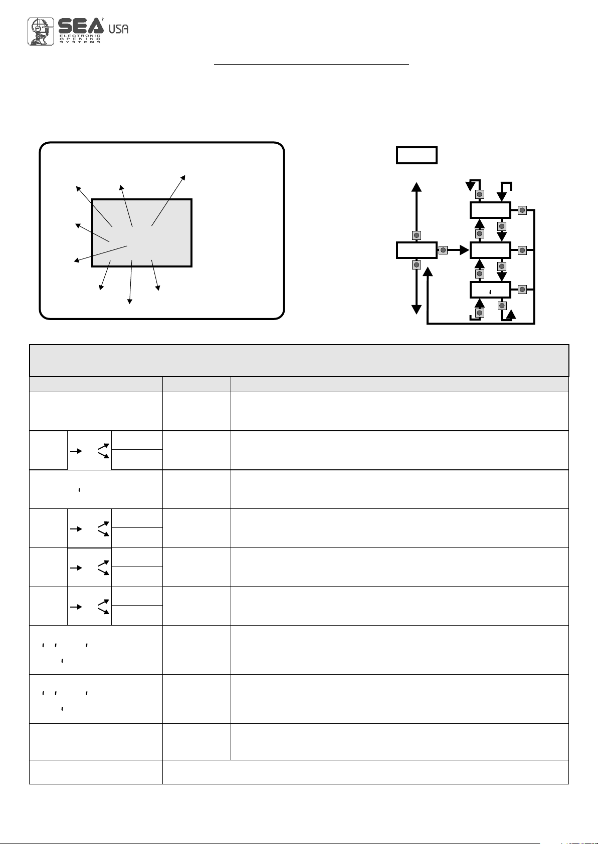
WORKING TIMES SELF LEARNING
Fig. 1 Fig. 2 Fig. 3
Fig.4
The control unit is pre-set with the default settings, to start the control unit with the DEFAULT settings just keep
pressed the UP and DOWN buttons at the same time power supplying the control unit the display shows the
message init.
The DEFAULT settings are shown in the Menues table.
NOTE: When using a B200 motor or magnetic limit switches in general; make sure that the control unit is set on magnetic limit switch
before learning.
MENU 34 - TYPE OF Li i T SUiT(X - AGNETI(
1) Disconnect the power supply, release the motor (Fig. 1) and put the leaves manually next to the stop in closing (Fig. 3-4).
2) Reset the mechanical lock (Fig. 2)
3) Select PROGRA ING on the display, press OK and than one of the UP or DOWN buttons. Now the gate will automatically execute a closing,
opening and reclosing cylce.
Note: If the motor starts in opening, remove and re-put power supply, select on the display REUERSE OTOR. And through the UP and DOWN
button put it on ON, or if you have the Jolly programmer, activate the motor and limit switch exchange function. If the motor starts in closing and
stops, remove the power supply and reverse the motor cables, then repeat the programming procedure.
4)The self-learning is done.
ATTENTION: This procedure is potentially dangerous and should only be performed by qualified personnel in safety conditions.
U U
U
FUNCTION LOGIC
AUTOMATIC LOGIC
Astart impulse opens the gate.A second impluse during the opening will not be accepted.
Astart impulse during closing reverses the movement.
SECURITY LOGIC
Astart impulse opens the gate.A second impulse during opening reverses the movement.
Astart impulse during closing reverses the movement.
STEP BY STEP TYPE 1 LOGIC
The start impulse follows the OPEN-STOP-CLOSE-STOP-OPEN logic.
STEP BY STEP TYPE 2 LOGIC
The start impulse follows the OPEN-STOP-CLOSE -OPEN logic.
DEAD MAN LOGIC
The gate opens as long as the START button of opening is pressed; releasing it the gate stops. The gate closes as long as the button connected
to the PEDESTRIAN START is pressed; releasing it the gate stops. To execute complete opening and/or closing cycles the related
pushbuttons must be constantly pressed.
2 PUSHBUTTONS LOGIC
One start opens, one pedestrian start closes. In opening the closing will not be accepted. In closing a start command reopens, a pedestrian start
command (closes) will be ignored.
NOTE 1: To have the automatic closing it is necessary to set a pause time, otherwise all the logic will be semi-automatic.
NOTE2: It is possible to choose, whether to accept or not, the start in pause, selecting in the MENU the item Start in paVse and
choosing ON or OFF. By default, the parameter is OFF.
UU
67411535 REV 07 - 06/2014
8

PRESS AT THE SAME TIME FOR 5 SECONDS TO ENTER OR TO EXIT THE SPECIAL MENU
MENU SP Default
SET
30 100
30 100
30 100
10 100
10 100
Off
5 100
Off
5 100
0.0 5.0
Setting from 30 to 100 * 80
* 40
* 80
* 70
* 70
Off
* 30
* 30
1 240
bvzzer
Off
Off on
Normal
Buzzer
Off
1 240
100 10e4
20 100
= start
Off
0 100
0 10e4
30
* 70
10e4
0
= start
1 - speed
2 - sloudoun speed
3 - learn ng speed
4 - open ng torq
5 - (los ng torq
7 - (los ng sloudoun
8 - preflasx ng
10 - (ourtesy l gxt
6 - open ng sloudoun
9 - flasx ng l gxt
Only (los ng
Nor al
U
L gxt
aluays
N (y(le
11 - traff ( l gxt reseruat on
12 - pedestr an open ng
13 - pedestr an PAUSE
14- a((elerat on
15 - a ntenan(e (y(les
U
16 - perfor ed (y(les
U
N (y(le
Nor al
U
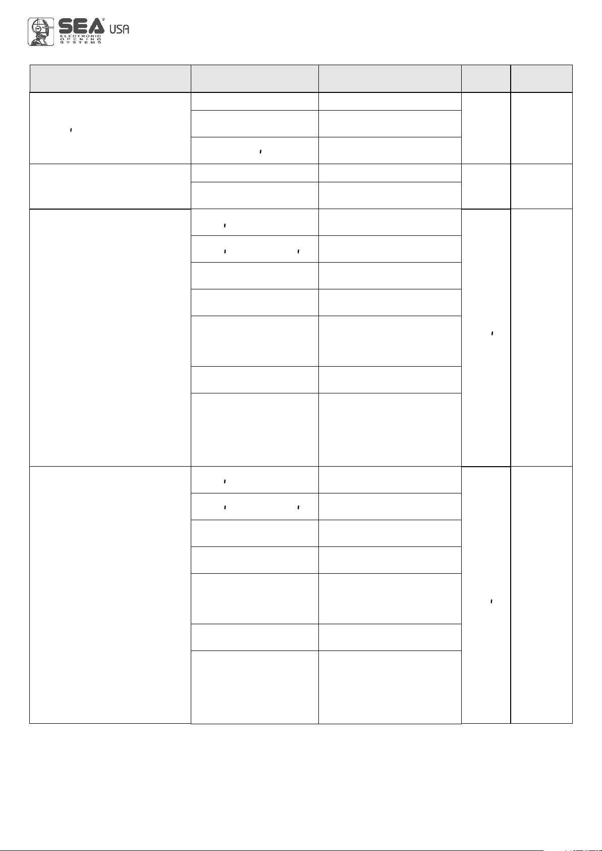
SPECIAL MENU FUNCTIONS TABLE USER 1 24V DG R1
UP and DOWN
press END or
UP and DOWN
For entering into the special menu move on one of the menu and press the
buttons at the same time for 5 s. For exiting the special menu move on one of the
menu and press the buttons at the same time for 5 s.
Description Set Value
Setting from 30 to 100
Setting from 30 to 100
Setting from 10 to 100
Setting from 10 to 100
Disabled
Disabled
Setting from 5 to 100
Setting from 5 to 100
Pre-flashing active only
before closing
Control lamp
Always ON
Disabled
Courtesy light setting
from 1s to 4min.
Setting from 20 to 100
Pause in pedestrian
opening same as in
total opening
Disabled
Acceleration ramp
Setting from 1s to 4 min.
Setting from 100 to
100000
Pre-flashing time
Courtesy light in cycle
When setting this function
the pedestrian input will be
activated to work on the
auxiliary board SEM
(traffic light management).
Reports the executed
cycles. Keep pressed OK
to reset the cycles
SPECIAL MENU
UPDOWN
International registered trademark n. 2.777.971
USER 1 - 24V DG R1
67411535 REV 07 - 06/2014 9
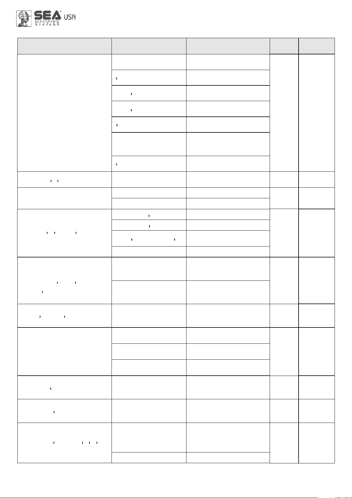
MENU SP Default
SET
stop
Nor al
U
17 - t er
U
off
8x2
off
Description Set Value
ON PXOTO2
ON PEDESTR AN ENTRY
Nor al
U
18 - edge
19 - PXOTO1
(LOS NG
Stop AND (LOSE
(LOSE
PAUSE RELOAD
OPEN NG AND (LOS NG
20 - PXOTO2
stop
(LOS NG
Stop AND (LOSE
(LOSE
PAUSE RELOAD
OPEN NG AND (LOS NG
(LOS NG
OPEN NG
Disabled
Timer function active
on photocell 2
Timer function active on
pedestrian input
Edge is active and
protected by a 8k2 resistor
Photocell active in closing
Photocell active in opening
and closing
The photocell gives a
command to close during
opening, pause and
closing
The photocell charging the
pausing time
Photocell active before
opening
The photocell stops in closing
and closes when released
Photocell active in closing
Photocell active in opening
and closing
The photocell gives a
command to close during
opening, pause and
closing
The photocell charging the
pausing time
Photocell active before
opening
The photocell stops in closing
and closes when released
Normal N.C. contact
If the photocell is occupied
during opening, pause or
closing, the gate reopens
completely and closes
without observing the
pause time.
If the photocell is occupied
during opening, pause or
closing, the gate reopens
completely and closes
without observing the
pause time.
Delay pause ti e
u
Delay pause ti e
u
International registered trademark n. 2.777.971
USER 1 - 24V DG R1
67411535 REV 07 - 06/2014
10
27 - fototest
0
0
* 10
off
off
Off
0 15
Off
1 100
Off
Off
On
1 10
0 100
0 100
Off
10 99
6
MENU SP Default
SET Description Set Value
22 - POS T ON RE(OUERY
23 - OTOR RELEASE
U
24 -ant ntrvs on
ONLY (LOS NG
ONLY OPEN NG
OPEN NG AND (LOS NG
26 -d agnost (S
25 - FLASX NG L GXT AND
t er
U
PXOTO1
PXOTO2
PXOTO1-2
29 - (LOS NG TOLERAN(E
28 -OPEN NG TOLERAN(E
30 - OPEN NG SENS T U TY
Regulates the recovery of
the motor inertia
Disabled
Setting from 1 to 100
Only on limit switch in opening
Only on limit switch in closing
On limit switches in closing
and in opening
Disabled
Shows last event
(See alarms table)
Auto-test active only on
Photo1
Auto-test active only on
Photo2
Auto-test active on
Photo1 and Photo2
Adjusts the amperometric
tolerance in relation to the
detected stop in closing
Adjust the amperometric
tolerance in relation to the
detected stop in opening
Disabled
PXOTO1-2
The flashing light remains
ON with active timer and
open gate
The flashing light remains
OFF with the active timer
and open gate
Adjustable from 10 to 99.
Increasing the value the
reversing on obstacles
will be delayed.
21 - 24u avx
ALUAYS
N (Y(LE
N pavsE
fototest
N (Y(lE AND fototest
OPEN NG
(LOS NG ALUAYS
AUX output always
power supplied
AUX output power
supplied only during opening
AUX output power
supplied only during closing
AUX output power
supplied only during pause
AUX output for
connection of photocell
TX to autotest
AUX output active only
during cycle
AUX output only during cycle
with fototest function active
International registered trademark n. 2.777.971
USER 1 - 24V DG R1
67411535 REV 07 - 06/2014 11
MENU SP Default
SET
---- ----
Mechanical limit switch
Description Set Value
35 - passuord
34 - TYPE OF L T SU T(X
U
U
E(XAN (AL
Agnet (
U
END
U
E(XAN (AL
Magnetic limit switch
Allows the entering of a
password which blocs the
modification of the control unit
parameters.
Select END and press OK to exit the special menu.
The special menu deactivates automatically after 20 minutes.
Note 1: The * indicates that the default value may change depending on the selected motor type.
Note 2: After initialization the parameters "motor type" and "limit switch type" remain son the value chosen in
the setup program.
0 50
33 - aster-slaue
U
aster
U
Slaue
off
off
0
* 10
Off
10 99
31 - (LOS NG SENS T U TY
32 - PXOTO off n (LOS NG
Disabled
Setting from 10 to 99
Setting from 0 to 50
For applications with two
motors in master-slave,
you can set the control
unit as slave
For applications with two
motors in master-slave, it
allows to set the control
unit as master
Disabled
With a new control unit all menus can be displayed and set and the password will be disabled.
Selecting one of the Menus and keeping UP and DOWN pressed at the same time for 5 seconds, you will access the
SP Menu containing the Passuord Submenu.
Pressing OK in the Passuord Menu, you will proceed with the entering of the numeric code of the 4-digit
PASSWORD.
Use UP and DOWN to increase or decrease the number, press OK to confirm it and you will pass automatically to the
entering of the next number. Pressing OK after the last entered number the word SvRE? appears, confirm the
activation of the PASSWORD and the message Ok appears, pressing UP or DOWN instead you can cancel the
operation and NO OPERATION will appear on the display.
Once entered the PASSWORD, it will be definitively activated, once the display switch off timeout has expired, or by
turning off and on again the control unit. Once the PASSWORD has been activated, the menus of the display can be
only displayed but not set. To unlock them you must enter the correct PASSWORD in the Passuord menu, if the
password is wrong the message ERRor will appear.
At this point, if the password has been entered correctly, the menus will be unlocked and it will be possible to change
the parameters of the control unit again.
If the control unit has been unlocked through Passuord Menu, it is possible to enter a new and different password,
using the same entering process as for the first one; at this point, the old password will no longer be valid.
If the password has been forgotten, the only way to unlock the control unit is to contact the SEA technical assistance,
which will assess whether to provide the procedure to unlock the control unit or not.
Note: The password cannot be set through the Jolly or Jolly 2 terminal.
PASSWORD ENTERING MANAGEMENT
International registered trademark n. 2.777.971
USER 1 - 24V DG R1
67411535 REV 07 - 06/2014
12
International registered trademark n. 2.777.971
USER 1 - 24V DG R1
The settings of the control unit are made through the UP, DOWN and OK buttons. The UP and DOWN buttons to scroll through the MENUS and
SUBMENUS. By pressing OK you enter from MENU into SUBMENU and confirm the choice.
Moving in the language menu pressing the UP and DOWN buttons at the same time you access the SP MENU for special settings.
Moving in the language menu pressing the OK button for 5 seconds, you enter the CHECK MENU, where you can check the operating status of
all inputs.
MENU
SEA
SET
---
--
---
DISPLAY INPUT STATUS
When the segment
is ON during self-
learning, the input
status is closed or
OFF.
Start
Start
pedestrian
Stop
Limit
Switch
opening
motor 1
Photocell 1
Photocell 2
Edge 1
Limit
Switch
closing
motor 1
Initial system
Software Version
Programming example
u.001
uerg
UP
OK
UP
UP
UP
DOWN
DOWN
DOWN
OK
OK
OK
DOWN
otor
U
S(orr
Jo nt
UP
start
EDGE
PHOTO1
PHOTO2
0.0u
END
MENU
Exit menu
MENU FUNCTION TABLE CHECK USER1 24V DG R1 INPUTS
To access the Menu for input check keep pressed OK for about 5 seconds.
Description Description
Start test
The contact must be N.O. If activating the related command on the
display the item SET lights up, the input will be working.
If SET is always on, check the wirings.
Stop test
Pedestrian
start test
The contact must be N.C. If activating the related command on the
display the item SET lights up, the input will be working.
If SET is always on, make sure that the contact is a N.C. one
The contact must be N.O. If activating the related command on the
display the item SET lights up, the input will be working.
If SET is always on, check the wirings
Safety
edge test
Photocell 1
test
Photocell 2
test
The contact must be N.C. If activating the related command on the
display the item SET lights up, the input will be working.
If SET is always on, make sure that the contact is a N.C. one
The contact must be N.C. If activating the related command on the
display the item SET lights up, the input will be working.
If SET is always on, make sure that the contact is a N.C. One
The contact must be N.C. If activating the related command on the
display the item SET lights up, the input will be working.
If SET is always on, make sure that the contact is a N.C. one.
Opening limit
switch test
Closing limit
switch test
The contact must be N.C. If activating the related command on the display
the item SET lights up, the input will be working. If SET is always on,
make sure that the contact is a N.C. one or that the related
limit switch is not occupied.
The contact must be N.C. If activating the related command on the display
the item SET will light up, the input will be working. If SET is always on,
make sur that the contact is a N.C. one or that the related
limit swith is not occupied.
Batteries’
voltage level Batteries charge level indicator
PedESTR AN Start
L T SU T(H
OPEN NG
U
L T SU T(H
(LOS NG
U
stop
enabled
OK
blo(ked
OK
OK
Note: If the Stop, Photocell 1 and Photocell 2 contacts are not bridged in self-learning, they will be deactivated
and can be reactivated through this menu, without repeating times self-learning.
enabled
blo(ked
enabled
blo(ked
OK
enabled
blo(ked
INPUT CHECK MENU
67411535 REV 07 - 06/2014 13

International registered trademark n. 2.777.971
USER 1 - 24V DG R1
RADIO TRANSMITTER SELF LEARNING
WITH RECEIVER ON BOARD OF CONTROL UNIT
!!
ROLLING CODE:
press twice
MENU
SEA
SET
MENU
SEA
SET
MENU
SEA
SET
OK
MENU
SEA
SET
UP
MENU
SEA
SET
MENU
SEA
SET
MENU
SEA
SET
MENU
SEA
SET
UP
MENU
SEA
SET
MENU
SEA
SET
UP
MENU
SEA
SET
MENU
SEA
SET
MENU
SEA
SET
UP
MENU
SEA
SET
MENU
SEA
SET
UP
MENU
OK
SEA
MENU
SEA
SET
MENU
SEA
SET
MENU
SEA
SET
SET
OK
OK
OK
OK
OK
OK
per 10 s.
TRANSMITTERS
START
PEDESTRIAN
START
EXTERNAL
MODULE
STOP
DELETE A
TRANSMITTER
0OK? OK
CLEAR
MEMORY OK
PRESS
BUTTON STORED
1 2 3 4
0
1
2
3
4
5
TABLE EXAMPLE
Transmitter
button
Memory
location Serial number Customer
STORED
STORED
STORED
PRESS
BUTTON
PRESS
BUTTON
PRESS
BUTTON
WARNING: Make the radio transmitters programming before you connect the antenna and insert the receiver into the
special CMR connector (if available) with turned off control unit.
With RF UNI module it will be possible to use both Coccinella Roll Plus transmitters, max. 800 codes (buttons), and radio
transmitters with fixed code, max. 100 codes (buttons). The first memorized radio transmitter will determine the type of the
remaining radio transmitters.
If the receiver is a Rolling Code, press twice the button of the radio transmitter that you want to program to memorize the first TX.
Notes:
- Enter radio transmitters learning only when the working cycle stops and the gate is closed.
- You can store max. 2 of the available 4 functions. If the control unit receives a code which was already associated to another function it will be
updated with the new function.
In the case of transmitters with fixed code it is necessary to press 1 time the button of the transmitter you want to program to store the first
remote control
FIXED CODE:
press once
If you want to program
the pedestrian
start as second
channel.
If you want to
program the
STOP as
second channel.
If you want to
delete a single
transmitter.
If you want to delete
the whole memory
If you want to program
the activation
of the LIGHT
output
as second channel.
Press the
button of the
transmitter
to be stored
Press the
button of the
transmitter
to be stored
Press the
button of the
transmitter
to be stored
Select with
UP or DOWN
the memory
location
to be deleted
and press OK
Press the
button of the
transmitter
to be stored
If you do not want to execute the cancellation,
press UP or DOWN to return to the
TRANSMITTER menu.
Confirm the cancellation.
67411535 REV 07 - 06/2014
14
International registered trademark n. 2.777.971
USER 1 - 24V DG R1
START - STOP - PEDESTRIAN START - ANTENNA -
PHOTOCELL
START (N.O.) The
An impulse given to this contact opens and closes the automation depending onthe selected logic it can be given by a key switch, a keypad,
etc. To connect the other devices refer to the related instructions leaflets. (ie. loop detectors and proximity switches).
Note1: In DEAD MAN logic it is necessary to keep pressed the Start for the opening of the automation.
Note2:
START is connected between the clamps 2 and 3 of the CN 1 terminal.
In 2 BUTTONS logic this button performs the opening.
STOP (N.C.) The STOP is connected between the clamps 2 and 5 of the CN1 terminal .
The pressure on this button immediately stops the motor in any condition/position. A start command is needed to re-start the movement.
After a stop the motor always re-starts in closing.
Photocell 1 and Photocell 2 Connections
+ = 24V (Accessories) max 750mA COM = 0V PH1 = Photocell contact 1
PH2 = Photocell contact 2
Note: For the autotest connect the TX to theAUX clamp and activate theAutotest function.
The standard setting of the photocell 1 is FOTO CLOSE and the one of the photocell 2 is FOTO
OPEN. The photocell 2 can be set also as TIMER (see TIMER function).
Note3: On the fototest menu you can also activate the self-test even on the single photocell.
Can be activated through on-board display or through the Jolly programmer. In both cases it’s a N.O. contact which provoques
the opening of the automation keeping it open until it is activated. When it’s released, the gate attends the set pausing time
and executes the reclosing. The TIMER command can be activated on the inputs FOTO2, START PEDESTRIAN.
Note1: When activated on the pedestrian entry, the pedestrian will be disabled also on the radio transmitter.
Note2: In case of intervention of a security device during the timer (Stop, Ammeter, Edge), to restore the movement it will be
necessary to give a start impulse.
Note3: In case of no power supply with open gate and active Timer the control unit will restore its use, otherwise if during
restore of the power supply the TIMER is not activated it will be necessary to give a start impulse for the reclosing.
TIMER
Antenna
Common
Start
Start ped.
Stop
Common
Photocell 1
CN1
1 2 3 4 5 6 7 8
Photocell 2
RX1
RX2
TX1
TX2
CN1
9 10 11 12 13
Common
24V (Accessories)
PEDESTRIAN START (N.O.) The pedestrian start can be connected
between the clamps 2 and 4 of the CN1 terminal .
This input allows a partial opening the opening space can be set through
the on-board display or through the JOLLY device.
Note1: The contact for partial opening is a N.O. Contact (Normally open).
Note2:In 2 BUTTONS logic it is necessary to keep pressed the Start Ped.
to re-close the automation.
Note3: In dead man logic this button executes the re-closing if you keep it
pressed.
Note4: When closed during pause, the gate will reclose only after this
input has been reopened.
TIMER activation: This input can be transformed into TIMER (See
TIMER).
Options AUX 24V max 200mA can be set with on-board
Display or with Jolly device.
Through the Jolly programmer it is possible to chose when having
tension on the AUX output. The options are: always, only during
opening, only during cycle, only before opening or only during
pause, fototest and in (y(le and fototest.
When using control units with batteries and / or solar panels, we
recommend connecting the accessories which are not used when
operator stands still (e.g. photocells) to a AUX output, setting the
option “in (y(le”. With this setting you can save energy by
lowering power consumption in stand-by, increasing the autonomy
of the system.
OPTIONS ON FOTO1 and FOTO2 adjustable on on- board display or with
JOLLY terminal.
FOTO CLOSE activation ((losing): if occupied, reverses the movement in closing, during
pause it prevent the closing.
Activation repeat pause (pavse RELOAD): If occupied, during pause it recharges the timer
of pause. In closing it reverses the movement.
FOTO OPEN activation (oPEning): If activated the photocell blocks the movement as long
as it’s busy, when released the opening continues.
FOTO PARK activation (stop and (lose) : in opening it is not active; in pause are activated
it commands the closing when released, otherwise it’s not active; in closing it stops the
movement as long as it is busy, when released the closing continues.
FOTO STOP activation (STOP): When activated before the opening the photocell blocks the
automation as long as it is busy, during the opening it will be ignored. In closing the
intervention of the photocell causes the reopening.
Activation PHOTO CLOSE IMMEDIATELY ((lose): The photocell stops the gate as long
as it is occupied in both opening and closing, when released it gives a closing command
(Closing one second after release of the photocell ).
delay pause ti e activation: If the photocell is occupied during opening, pause or
closing, the gate reopens completely and closes without observing the pause time.
u
67411535 REV 07 - 06/2014 15
16
Sensor barriers
This control unit comes with a detection device of motor current absorbtion which allows to
reveal possible obstacles during the opening and the closing of the gate. When this device
intervenes in opening it causes the inversion of the movement for around a second, if it
intervenes in closing it causes the total reopening.
Note1: The ammeter sensitivity is adjustable both in opening and in closing through
the on-board display or through the JOLLY terminal. With high torque the gate
reverses after 5 seconds.
Attention: In case of obstacle, if the automatic reclosing is on, the gate will attempt
to close for 3 times, whereupon a start signal will be necessary to re-establish the
movment.
Limit
Switch
CN2
Flashings Number
9
2
3
6
4
Flashings Number
5
7
6
4 fast
Kind of alarm
Motors fault
Photocell in closing
Photocell in opening
Opening impact
Safety edge
Kind of alarm
Stop
Max. Reached cycles
Closing impact
Limit switch error
Nota1: se nella diagnostica viene visualizzato “Cicli massimi raggiunti”, effettuare la manutenzione e/o azzerare il numero di cicli
eseguiti.
Note2: To exit from the error messages, press OK. If the error persists, make all required checks for the specific error and / or
disconnect the device that generates the error to see if the error disappears.
At each opening and closing of the automation the flashing light will blink. It blinks once per second during opening and twice per
second during closing, while it remains lit during pause.
It is possible to view the alarms also on the flashing light or on the control lamp, simply by observing the number of flashes emitted and
verifying the reference in the table below:
International registered trademark n. 2.777.971
USER 1 - 24V DG R1
LIMIT SWITCH AND SENSOR BARRIERS
ALARMS INDICATIONS
Limit switch
The limit switch can be connected through the special LIMIT SWITCH connector
on the control unit. The control unit can administrate mechanical, inductive and
magnetic limit switches. Only on some special applications il will not be
necessary to connect the limit switches. The control unit will automatically realize
if limit switches are present or not.
1) Through the on-board display or through the JOLLY programmer it is possible
to activate the ani-intrusion function. This function is lied to the presence of at
least one limit switch which, when free, forces the motor to re-close.
Note: if during programming phase the motor and limit switch times should
not be in phase between them, the gate will start in closing, it stops and will
not complete the selflearning of the times, at this point it will be necessary
to switch off the tension and to invert the cables of the motor. The first
movement in selflearning must always be executed in closing.
ATTENTION: When using SEA magnetic limit switches, make sure that the
motor is set on Agneti( li it suitcK present in the special menu.
UU
Signals Kind of alarm Solutions
Motors current failure Sure there are no short circuits on the motor or on the control unit.
24V Power supply
failure
Make sure there are no short circuits on the wiring or on the control unit and
no overloads.
AUX output
voltage failure Make sure there are no short circuits on wiring or control unit and no overload.
Self-test photocells
failure Check the photocells operation and / or connections on the control unit.
Limit switch
activation failure
Check the operation of both limit switches and / or correspondence
between movement direction of the motor and engaged limit switches.
Flashing lamp failure Check connections and / or conditions of the lamp.
Slave failure Check the connection between MASTER and SLAVE or if the SLAVE board is
actually set as such.
FA LVRE OTOR
u
FA LVRE24
FA LVRE24UAVK
FA LVRE SELF TEST
FA LVRE L T SU TCK
U
FA LVRE slaue
FA LVRE FLASK NG L GKT
67411535 REV 07 - 06/2014
9 10 11 12 13
Edge
AUX
Common
FL(-)
CN1
Security edge
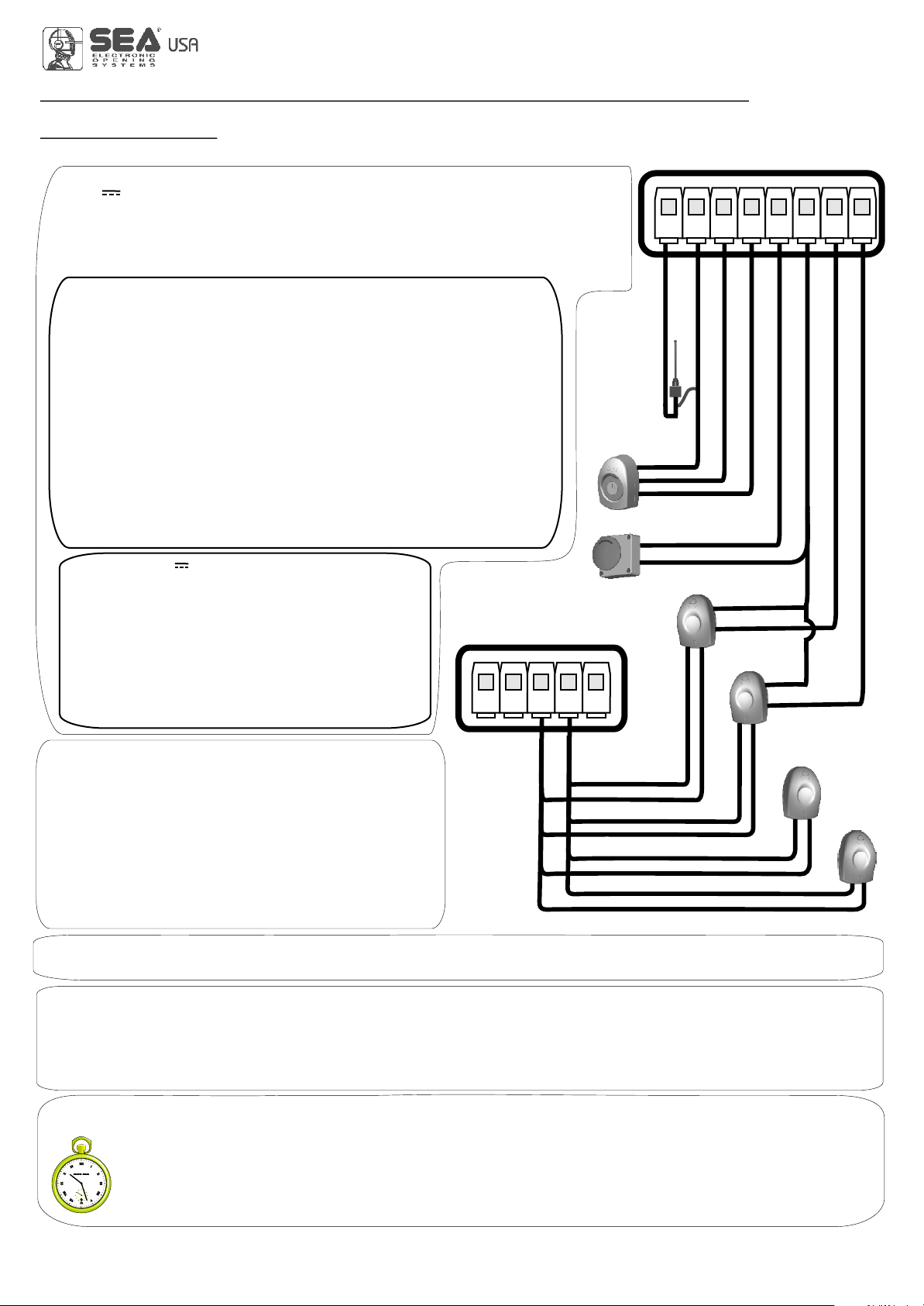
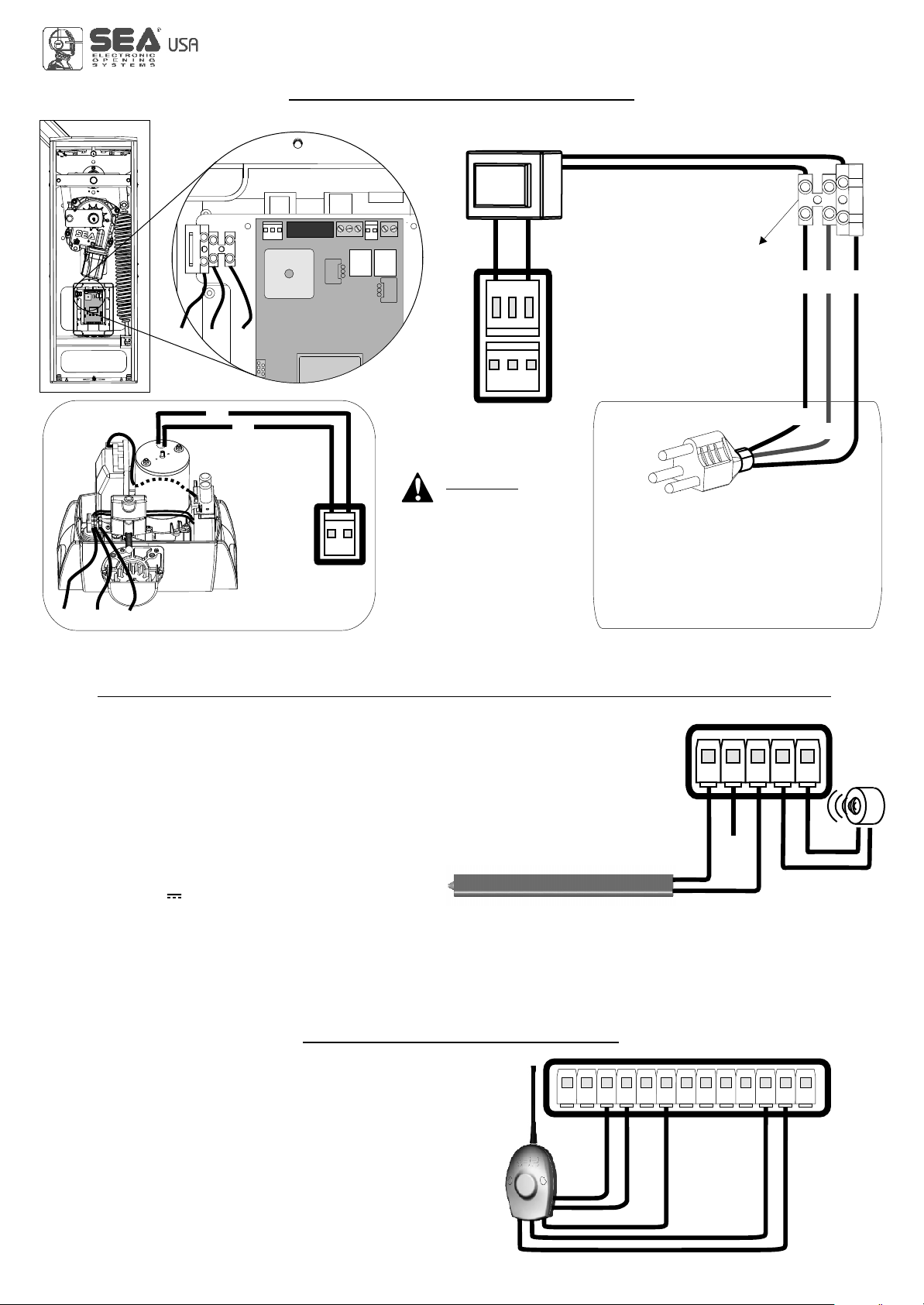
MOTOR POWER SUPPLY
Power input
Input for the connection of the electric
power.
P = SINGLE PHASE 120V~
N = NEUTRAL
G = GROUND NOTICE: for the
connection to the electric
power see the law in force.
TRANSFORMER
3,6 A blow fuse on 230V ~ power supply
6,3A blow fuse on 115V ~ power supply
17
GN
115V~
o
230V~
P
POWER
(CN8)
P G N
MOTOR
(CN6)
M+
M- 12
P G N
+
-
CN1
1 2 3 4 5 6 7 8 9 10 11 12 13
Start
SECURITY EDGE
Between clamps 9 and 11 of CN 1 it is possible to connect an active safety edge on the terminal M8. If this
device is pressed it opens the contact causing a partial inversion of the movement both in opening and in
closing. If not used you must put a jumper between the contacts GND and 9 of CN1.
Note1: contact N.C.
Note2: Through the on-board display or the Jolly programmer it is possible to activate the balanced edge
8K2, in this case the edge contact is controled by a special resistance value revealing the eventual
involuntary short- circuit of the device. In case of imbalance of the device a special alarm will show on the
on-board dispaly or on the JOLLY programmer.
SECURITY EDGE AND WARNING LAMP OR BUZZER
EXTERNAL RECEIVER
Example: Connection of a
radio receiver
For the connection of the
receiver refer to the relative
instructions manual.
Common
Common
Start ped.
-
+
Flashing Lamp 24V 15W (Warning lamp ) or Buzzer
The flashing lamp or buzzer can be connected between the clamps 24V (Accessories) and FL (-) of CN 1.
The warning lamp or buzzer advises that the automatic gate is moving with 1 flash/second in opening and 2 flashes / second in closing. During
pause it remains switched on. Through the warning lamp or buzzer it is also possible to identify alarms lied to the STOP, PHOTOCELL 1,
PHOTOCELL 2 and EDGE devices. Through the display or the JOLLY programmer it is possible to activate the pre-flashing function and/or to
modify the function of the warning lamp/buzzer choosing between fix flashing, control lamp or Buzzer.
WARNING:
Keep the power
cables (motors, power
supply) SEPARATE from the
command cables (push
buttons, photocells and so
on). In order to avoid any
interference it’s preferable to
foresee and use two separate
sheaths.
BUZZER
International registered trademark n. 2.777.971
USER 1 - 24V DG R1
24V (Accessories)
24V (Accessories)
67411535 REV 07 - 06/2014

18
MASTER-SLAVE FUNCTION
CN4
SIGB
COM
SIGA
SIGB
COM
SIGA
M1 M1
To set an installation with two motors in MASTER-SLAVE function it is recommended to do as follows:
1) Set the two motors as if they were two independent installations, make sure that the individual motor works
properly and that the limit switches (when present) are read properly.
2) Once sure of the correct functioning connect the control unit MASTER to the control unit SLAVE through the
special clamp (Code SEA23001220).
3) Now set the control unit, which has to manage the commands and motor 1 (photocell, keyswitch, STOP, safety
edge etc.) as MASTER and the other one which will move motor 2 as SLAVE.
4) Follow up the selflearning of the times of the MASTER control unit.
Note 1: The master and slave settings on the control unit are present in the special menu selecting ASter-slaue.
Note 2:All these operations can also be managed through the JOLLY programmer).
Note 3: On the SLAVE it is possible to set the following functions only: torque, speed, motor type, slowdown speed,
acceleration, deceleration, position recovery, AUX and motor inversion. All other parameters will be set only by the
MASTER control unit.
U
Insert on CN4
of the Master control unit
Insert on CN4
of the Slave control unit
Note: respect the polarity of the cables.
It is recommended to use a two twisted pairs shielded
2
cable with less than 0.5 mm section.
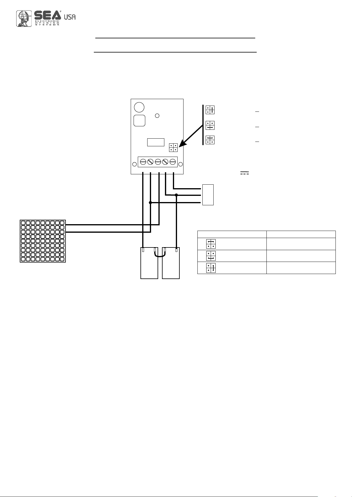
TRAFFIC LIGHT CARD CONNECTION
1 2 3 4 5 6 7 8 9 10 11 12 13
EXP
DS1
DS2
RL4 RL3 RL2 RL1
L4 L3 L2
IC2
-M2+
1 CNP
CN1
L1
M1
24V~ / (ac/dc)
or
230V~
1 2 3 4 5 6 7 8
1
2
3
4
Connect on
EXP terminal
International registered trademark n. 2.777.971
USER 1 - 24V DG R1
67411535 REV 07 - 06/2014
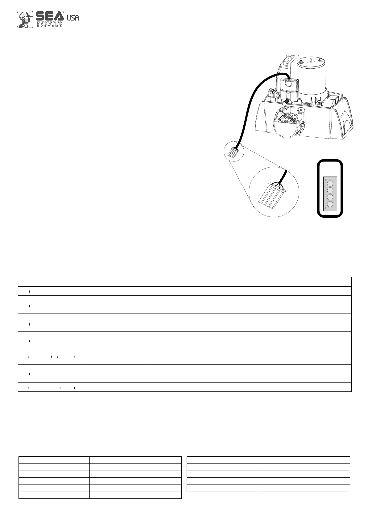
28V Battery charger
Positive battery
Negative battery charger
Battery current (mA) Battery (Ah)
Insert two 12V batteries connected in series.
= charge 200mA
~
~
(BAT)
+
-
GND
PSOL
BAT 28V
+
-
GND
+
CN1
+
-
S
GNDGND
Solar Panel
Batteries
12V 12V
= charge 360mA
= charge 800mA
~
Cod.23101105
800
360
200
12 or 16
7
2
19
International registered trademark n. 2.777.971
USER 1 - 24V DG R1
CONNECTION OF BATTERIES
TO BATTERY CHARGER CARD
Specifications of
optional batteries:
24V Pb 1.2Ah min.
67411535 REV 07 - 06/2014
Page for both instaler and user
WAREHOUSING TEMPERATURES
Tmin TMax Dampnessmin DampnessMax
5% Not condensing 90% Not condensing
MAINTENANCE
Considering the number of working cycles and the kind of gate, if the gate has changed the clutches and doesn’t work
it’s necessary to periodically proceed, with the learning times reprogramming on the electronic control unit.
Periodically clean the optical systems of the photocells.
REPLACEMENTS
Any request for spare parts must be sent to:
Tel. - Toll free:
SAFETYAND ENVIRONMENTAL COMPATIBILITY
Disposal of the packaging materials of products and/or circuits should take place in an approved disposal facility.
STORING
Materials handling must be made with appropriate vehicles..
WARRANTY LIMITS
SEA reserves the right to make any required modification or change to the products and/or to this manual without any
advanced notice obligation.
SEA USA Inc. 10850 N.W. 21st unit 160 DORAL MIAMI Florida (FL) 33172 USA
:++1-305.594.1151 ++1-305.594.7325 800.689.4716
For the guarantee see the sales conditions on the official SEAprice list.
-4 °F + 149 °F
20
International registered trademark n. 2.777.971
USER 1 - 24V DG R1
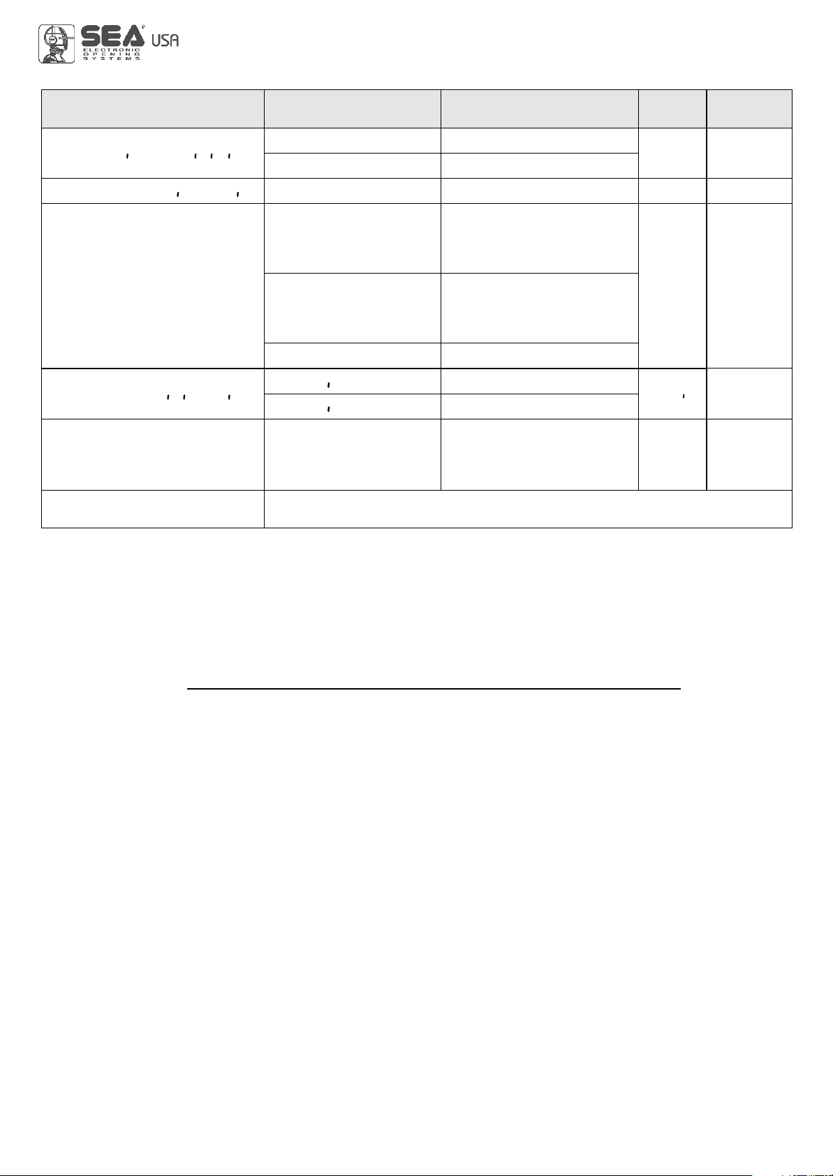
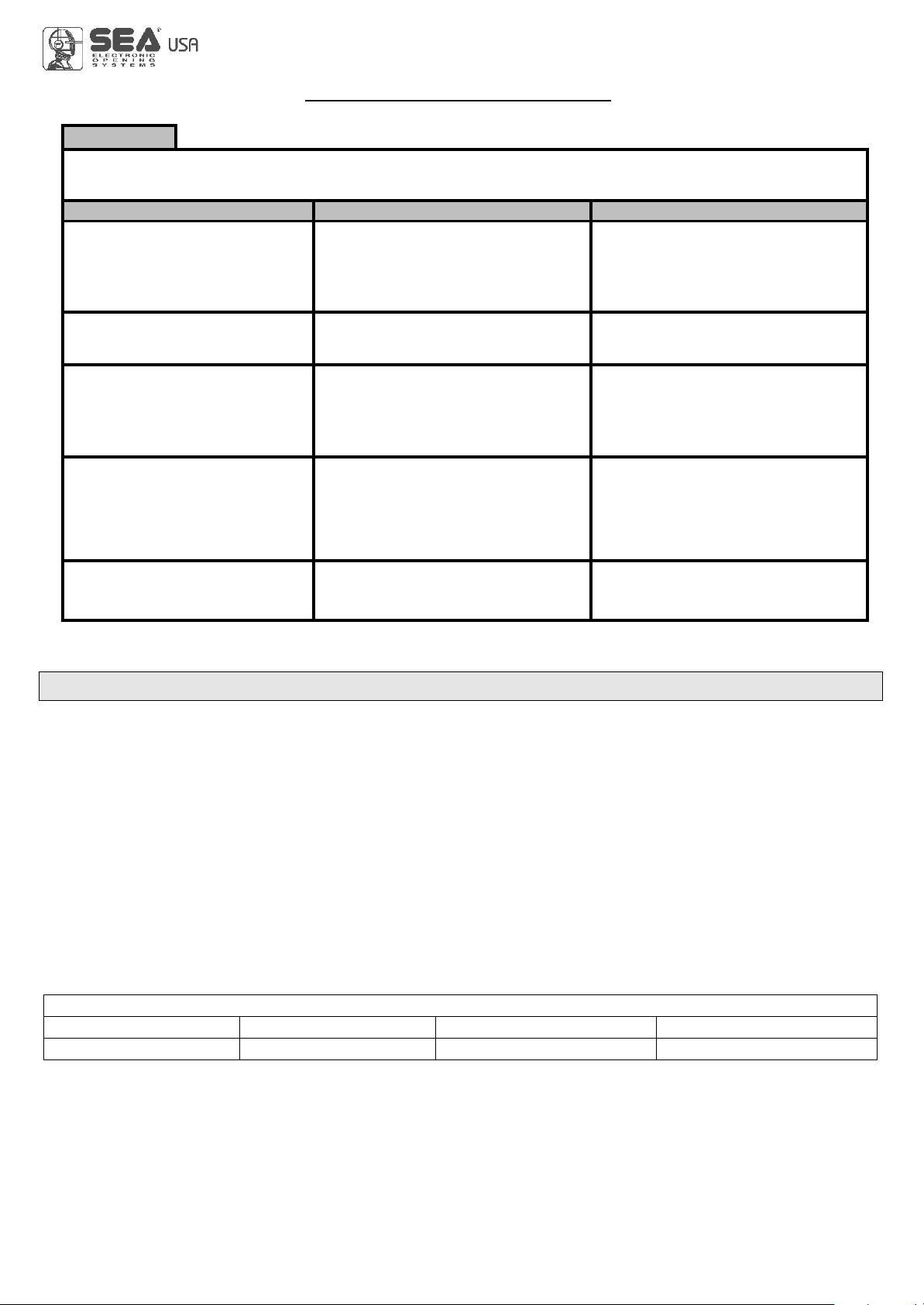
TROUBLE SHOOTING
Advises
Make sure all Safeties are turned ON
Problem Found Possibile Cause Solutions
Motor doesn’t respond to any
START impulse
Gate doesn’t move while the
motor is running
Gate doesn’t reach the complete
Open / Closed position
The gate opens but doesn’t
close
The gate doesn’t close
automatically
a.) Check the connected N.C. contacts
b.) Burnt fuse
a.) The motor is in the released position
b.) There is an obstacle
a.) Pause time set to high
b.) Control unit in semi-autom. logic
a.) Wrong setting of the limit switches
b.) Error on programming
c.) Gate is stopped by an obstacle
d.) Torque or speed too low
a.)
.) Ammeter alarm
The contacts of the photocells are
connected and open
b.) The stop contact is connected and open
c.) The edge contact is open
d
a.) Check the connections or the jumpers
on the connections of the safety edge or
of the stop and of the photocell if connected
b.) Replace the burned fuse on the
control unit
a.) Re-lock the motor
b.) Remove obstacle
a.) Adjust pause time
a.) Set limit switches
b.) Repeat programming
c.) Remove obstacle
d.) Increase torque parameter
a.) b.) c.) Check the jumpers or the
connected devices and the signals
indicated on the warning lamp
d.) Check if the ammeter alarm has
intervened and eventually increase the
torque parameter.
b.) Set the pause parameter on a
different value from the off
67411535 REV 07 - 06/2014
Table of contents
Popular Controllers manuals by other brands

Mateksys
Mateksys F411-WSE quick start guide

Damega
Damega Intel Siren Installation instructions manual

Honeywell
Honeywell SUPER TRADELINE S8610U Quick reference guide

PS Automation
PS Automation PSL Series Short operating instructions

ABB
ABB CBXi-8R8 Installation and Wiring

ComAp
ComAp IL-NT MRS15 reference guide


Texas Instruments
Texas Instruments bq24725A manual

GE
GE Masoneilan 4700E instruction manual

Meunier Technologies
Meunier Technologies DICE ES Installation, operation and maintenance manual

enphase
enphase EP200G101 Quick install guide

HighPoint
HighPoint SSD7505 Quick installation guide

Regin
Regin REGIO EEDO manual