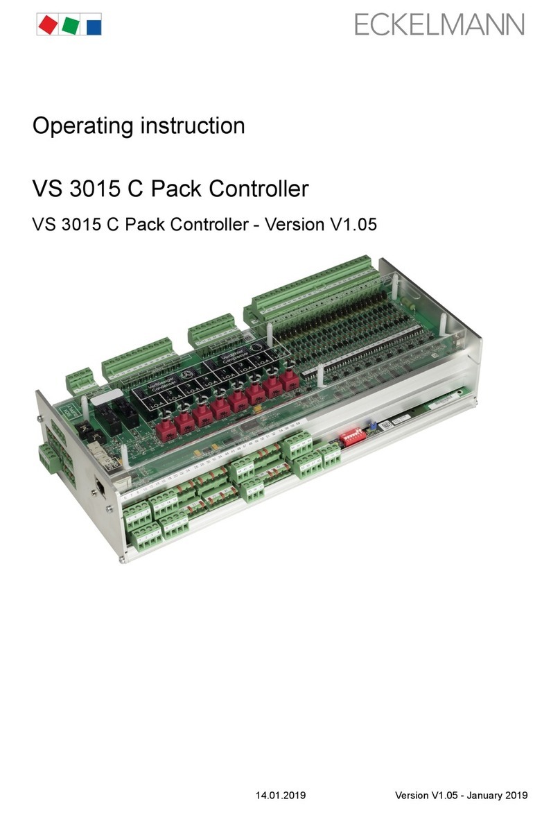
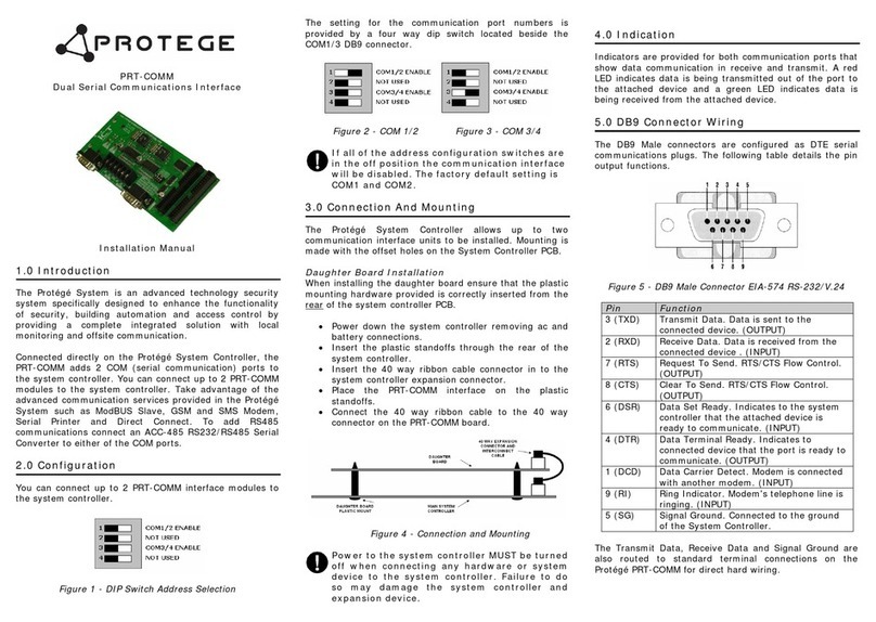
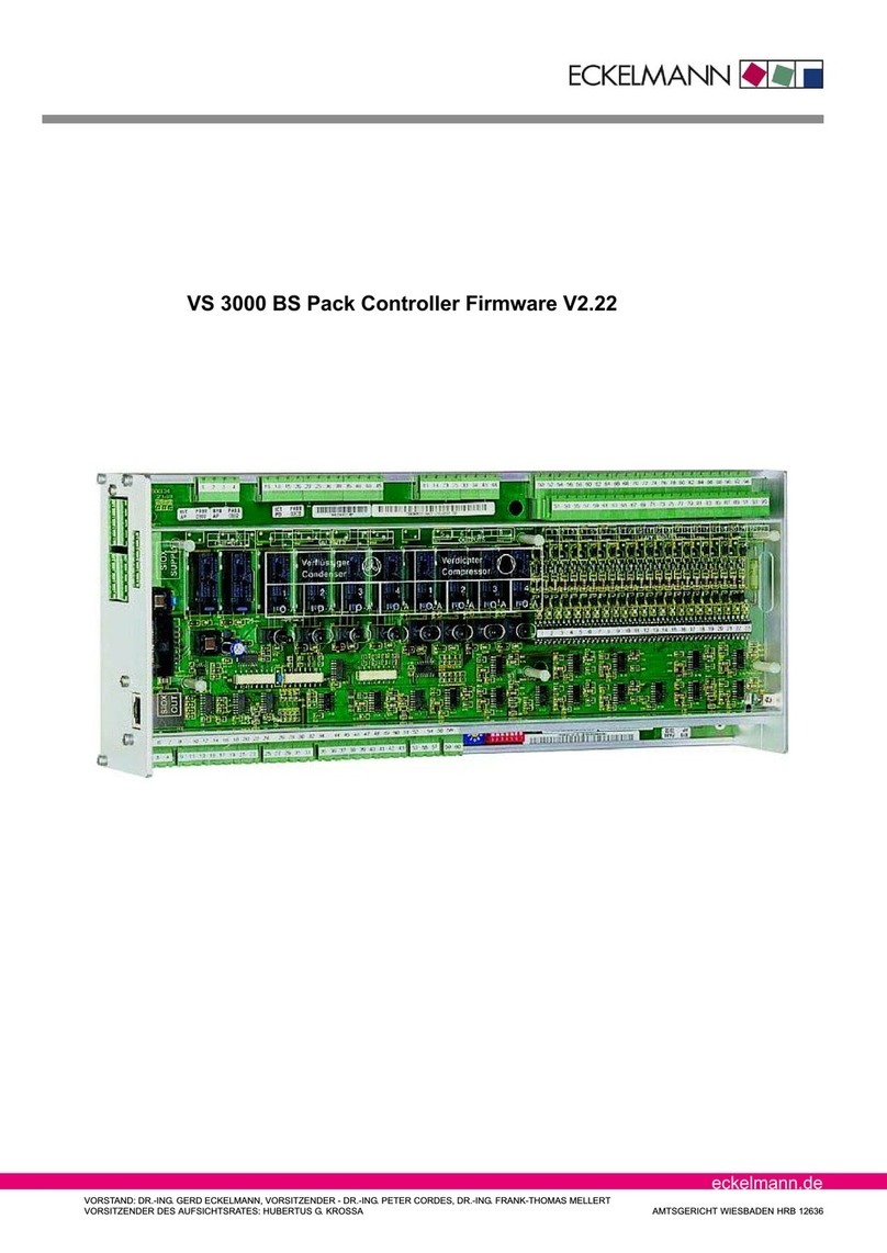
ECKELMANN VS 3000 User manual

eckelmann.de
VORSTAND: DR.-ING. GERD ECKELMANN, VORSITZENDER - DR.-ING. PETER CORDES, DR.-ING. FRANK-THOMAS MELLERT
VORSITZENDER DES AUFSICHTSRATES: HUBERTUS G. KROSSA AMTSGERICHT WIESBADEN HRB 12636
VS 3000 Pack Controller
Firmware V3.00


Version 2.02 15.05.2007
eckelmann.de
E2007 - ECKELMANN AG | BERLINER STRASSE 161 | 65205 WIESBADEN | TELEFON +49(0)611 71 03-0 | FAX +49(0)611 71 03-133
eckelmann.de
vii
1 System Design of VS 3000 1...................................................
2 Application of VS 3000 3......................................................
3 Function of VS 3000 5.........................................................
3.1 System configuration 5.........................................................
3.2 Low-pressure control / Compressor control 5......................................
3.2.1 Setting parameters for LP transducer characteristic 6...............................
3.2.2 Neutral zone 6.................................................................
3.2.3 Control algorithm 6.............................................................
3.2.4 Control algorithm with step controller 7............................................
3.2.5 Control algorithm with combined controller 8.......................................
3.3 Loading and unloading fixed-speed compressors 9.................................
3.4 COP optimization 11...........................................................
3.5 Compressor control times 11....................................................
3.6 Calculating setpoint 12.........................................................
3.6.1 Calculating setpoint by outdoor temperature 12...................................
3.6.2 Demand-dependent calculation of setpoint 13.....................................
3.7 Processing load-level information 14.............................................
3.8 Response to fault conditions 14.................................................
3.9 Demand-dependent setpoint shift parameters 14..................................
3.10 Humidity shift 15..............................................................
3.11 Ambient data 15..............................................................
3.12 Second setpoint - Setpoint increase/decrease 16..................................
3.13 Refrigeration compressor packs with oil equalizer 16...............................
3.14 Capacity-controlled compressors 16.............................................
3.15 Load shedding 18.............................................................
3.16 Emergency power mode 18....................................................
3.17 Compressor base load rotation 18...............................................
3.17.1 Base load rotation with variable-speed compressors 19............................
3.18 Compressor monitoring 20.....................................................
3.19 Safety loop 20................................................................
3.20 Monitoring of motor overload cutout 20...........................................
3.21 Monitoring low oil pressure cutout 21............................................
3.22 Monitoring cylinder head temperature 22.........................................

Version 2.02 15.05.2007
viii
3.23 Monitoring high pressure 23....................................................
3.24 CO2 cascade 24..............................................................
3.25 Monitoring low pressure 26.....................................................
3.26 Monitoring compressor starts 26................................................
3.27 High-pressure control / Condenser control 27.....................................
3.27.1 Setting parameter for HP transducer characteristic 27..............................
3.27.2 Neutral zone 27...............................................................
3.27.3 Control algorithm 28...........................................................
3.27.4 Control algorithm with step controller 28..........................................
3.27.5 Calculating setpoint with step controller 29........................................
3.27.6 Condenser fan control times with step controller 29................................
3.27.7 Control algorithm with continuous control 31......................................
3.27.8 Calculating setpoint with continuous control 32....................................
3.27.8.1 Control algorithm with parallel combined controller 33..............................
3.27.8.2 Control algorithm for staged combined controller 35................................
3.27.9 Heat recovery mode 37........................................................
3.28 HP setpoint increase 38........................................................
3.29 Fan protection / HP base load rotation 38........................................
3.30 Monitoring condenser fan motors 39.............................................
3.31 Starting characteristics 40......................................................
3.31.1 First start 40..................................................................
3.31.2 Restart 40....................................................................
3.32 Monitoring refrigerant level 40..................................................
3.33 Monitoring burst disk 40........................................................
3.34 Monitoring external alarm / speed adjuster 41.....................................
3.35 Disabling refrigeration points 41.................................................
3.36 Discharge gas defrosting 41....................................................
3.36.1 Setpoints for discharge gas defrosting 42.........................................
3.36.2 Actual values for discharge gas defrosting 43.....................................
3.36.3 Manual control of D2D 43......................................................
3.36.4 Discharge gas defrosting in fault conditions 43....................................
3.36.5 Sequence of joint Z2 discharge gas defrosting 44..................................
3.36.6 Sequence of Z2 display case discharge gas defrosting 45..........................
3.36.7 Sequence of Z2 discharge gas defrosting with coldroom defrost mode
set to El. With UA 300 46......................................................
3.36.8 Sequence of Z2 coldroom discharge gas defrosting 47.............................
3.37 Archiving of operating data 48..................................................
3.37.1 Compressor/fan operating hours 48.............................................

Version 2.02 15.05.2007
eckelmann.de
E2007 - ECKELMANN AG | BERLINER STRASSE 161 | 65205 WIESBADEN | TELEFON +49(0)611 71 03-0 | FAX +49(0)611 71 03-133
eckelmann.de
ix
3.37.2 Daily run times and compressor starts 48.........................................
3.37.3 Compressor pack activity/utilization 48...........................................
4 Installation and Startup of VS 3000 49.........................................
4.1 Connection and safety notes 49.................................................
4.2 Installation 50.................................................................
4.3 Basic parameter settings on hardware 50.........................................
4.3.1 Basic settings with S1 51.......................................................
4.3.2 Basic settings with S2 53.......................................................
4.4 Basic parameter settings in software 54..........................................
4.5 Replacing the battery 55.......................................................
4.6 Installing update software 57....................................................
4.6.1 Installing update software on the PC 57..........................................
4.6.2 Updating current firmware in VS 3000 58.........................................
5 Pin and Terminal Assignments of VS 3000 61..................................
5.1 Pin assignments 62...........................................................
5.2 Inputs/outputs for 4 compressor capacity stages / 4 fan stages 65...................
5.3 Inputs/outputs for 8 compressor capacity stages / 8 fan stages 68...................
5.4 Inputs/outputs for 12 compressor capacity/12 fan stages 71.........................
5.5 Inputs/outputs of SIOX D2D extension module for discharge gas defrosting 75........
6 Operating Modes of VS 3000 77...............................................
6.1 Emergency manual-automatic mode selection 77..................................
6.2 Service mode 77..............................................................
6.3 Displaying operating status 78..................................................
7 Operation of VS 3000 79......................................................
7.1 Operation with CI 3000 Store Computer or AL 300 Operator Terminal 79.............
7.2 Menus and screens 80.........................................................
7.3 Operation / Parameter setting of VS 3000 Pack Controller 84.......................
8 Menu Structure of VS 3000 85.................................................
8.1 Menu tree 86.................................................................
8.1.1 Menu 0 Main Menu 88.........................................................
8.1.2 Menu 1 Summery 88..........................................................
8.1.3 Menu 2 Actual Values 88.......................................................
8.1.4 Menu 3 Setpoints 92...........................................................

Version 2.02 15.05.2007
x
8.1.5 Menu 4 Clock 109.............................................................
8.1.6 Menu 5 Messages 110..........................................................
8.1.7 Menu 6 Operating data 111......................................................
8.1.8 Menu 7 Default settings 113.....................................................
8.1.9 Menu 8 Service Mode 113.......................................................
9 Alarms and Messages of VS 3000 115.........................................
9.1 Reporting system 115..........................................................
9.2 Structure of alarms/messages 115................................................
9.3 Types of alarm 116.............................................................
9.3.1 Process fault alarms 116........................................................
9.3.2 System fault alarms 118........................................................
10 Specifications of VS 3000 119.................................................
10.1 Electrical Data of VS 3000 119...................................................
10.2 Mechanical data of VS 3000 120................................................
10.3 Mechanical data of SIOX extension module 120...................................

Version 2.02 15.05.2007
System Design of VS 3000
1
eckelmann.de
E2007 - ECKELMANN AG | BERLINER STRASSE 161 | 65205 WIESBADEN | TELEFON +49(0)611 71 03-0 | FAX +49(0)611 71 03-133
The basic construction of the VS 3000 Pack Controller consists of:
- One analog module
- One digital I/O module
The controller is of modular design and can be upgraded to a maximum of three SIOX extension modules in all
(see illustration below). The following expansion stages are available:
Base module
VS 3000
TTY
RS 232/485
CAN bus
CI 350
GLT
LDS new
Base module
4 compressors and
4 fans
Base module with one extension module
8 compressors and 8 fans
Base module with two extension modules
12 compressors and 12 fans
Optionally for
hotgas defrost
Optionally for
hotgas defrost
Optionally for
hotgas defrost
SIOXSIOX SIOX
OUT
IN
OUT
IN
OUT
IN
SIOX Supply
ZNR. 51203 55 030 E2
2 x anlog output
0..10V (4..20 mA)
(speed actuator FC)
23 x digital inputs 230 V
1 x input humidity sensor
4...20 mA (0..10V)
14 x analog input
temperature sonde PT1000
(e.g. cylinder head temp.)
2 x analog inputs
4...20 mA (0..10V)
(e.g. pressure transmitter)
Extension module
SIOX
Extension module
SIOX
Extension module
SIOX
12 x digital inputs 230 V
12 x digital inputs 230 V
12 x digital inputs 230 V
Digital output
4 x two-way
contact
4 x normal open
contact
Digital output
4 x two-way
contact
4 x normal open
contact
Digital output
4 x two-way
contact
4 x normal open
contact
Digital output
4 x two-way contact
4 x normal open
contact
CI 3000
AL 300
MODEESC
PRIO 1
PRIO 2
,
9
WXYZ
7
PQRS
8
TUV
6
MNO
4
GHI
5
JKL
3
DEF
2
ABC
1
0
ALARM
RESET
See Section 5 Pin and Terminal Assignments for electrical connection of the VS 3000 Pack Controller.
Basic version
Digital inputs/outputs
23 inputs 230 V
10 outputs 230 V - Relay outputs
1 System Design of VS 3000

Version 2.02 15.05.2007 System Design of VS 3000
2
Analog inputs/outputs
14 inputs PT1000 - Connection for PT1000 temperature sensors
2 inputs / 4-20 mA (0-10 V) - Connection for pressure transducers
1 input / 4-20 mA (0-10 V) - Connection for humidity sensors
1 output / 0-10 V (0-20 mA) - Connection for speed adjuster for continuous fan control
1 output / 0-10 V (0-20 mA) - Connection for frequency changer for variable-speed compressors
SIOX Supply - Power supply for SIOX extension module
Ports:
CAN-Bus: Communication within new ESLDS System
TTY: Communication within earlier ESLDS System
RS232: Communication between ESLDS System and building control system,
connection for firmware update
RS485: Connection for building control system (BCS)
SIOX OUT: Connection for data transfer to SIOX extension modules
New features compared to earlier versions
From Version 3.00:
- High-pressure monitoring
-CO
2cascade
- changes to single- and multi-stage compressors (Standstill Time S1) / Starts
From Version 2.98:
- High-pressure combined controller
- D2D defrost sequence

Version 2.02 15.05.2007
Application of VS 3000
3
eckelmann.de
E2007 - ECKELMANN AG | BERLINER STRASSE 161 | 65205 WIESBADEN | TELEFON +49(0)611 71 03-0 | FAX +49(0)611 71 03-133
Functions provided in the VS 3000 Pack Controller for refrigeration compressor packs and condensers are as
follows:
SControl
SRegulation
SFault reporting
SFault archiving
SMonitoring
SArchiving
These functions are as follows:
Compressor control (step controller) for single-circuit systems equipped with maximum
6 compressors each with 2 capacity stages or
4 compressors each with 3 capacity stages or
12 stand-alone compressors without capacity control
Low-pressure control/compressor control:
- Step controller
- Combined controller
Base load rotation
Compressor monitoring
Load shedding
High-pressure control/fan control
- Step controller
- Combined controller
Base load rotation/Fan overload protection
Data archiving:
- Messages
-Starts
-Runtimes
- Activity/Utilization
2 Application of VS 3000

Version 2.02 15.05.2007 Application of VS 3000
4
Liquid level monitoring
- M- Motor overload cutout (fans)
- Motor overload cutout (compressors)
- Bursting disk
- Low oil pressure cutout
- Cylinder head temperature
- High pressure
- Low pressure
- Refrigerant level
- External alarm
Discharge gas defrosting:
- D2D two-pipe system

Version 2.02 15.05.2007
Function of VS 3000
5
eckelmann.de
E2007 - ECKELMANN AG | BERLINER STRASSE 161 | 65205 WIESBADEN | TELEFON +49(0)611 71 03-0 | FAX +49(0)611 71 03-133
3.1 System configuration
The VS 3000 Pack Controller contains a low-pressure control loop (LP, compressor control) and a high-pressure
control loop (HP, condenser control). Two different temperature ranges are provided for compressor control (NT:
normal-temperature refrigeration or LT: low-temperature refrigeration; see also Section 2 - Application).
Compressor control largely covers the following control and regulating functions:
Low-pressure control (LP, compressor control) for single-circuit systems - step or combined control
SLoad shedding
SEmergency power mode
SBase load rotation
SCompressor monitoring
SSafety loop
SD2D two-pipe discharge gas defrosting
High-pressure control (HP, condenser control) for single-circuit systems - step or speed control
3.2 Low-pressure control / Compressor control
SStep controller
- Control by loading and unloading compressor stages or compressor capacity stages
SCombined controller
- Control by variable-speed compressor in combination with one or more fixed-speed compressors
The setpoint is defined as a function of room (ambient) temperature. Actual values are detected by a pressure
transducer with continuous current output (4 to 20 mA) or voltage output (0 to 10 V).
3 Function of VS 3000

Version 2.02 15.05.2007 Function of VS 3000
6
3.2.1 Setting parameters for LP transducer characteristic
The VS 3000 Pack Controller works with linear-characteristic continuous pressure transducers. The pressure in-
puts can be matched to various transducers with linear characteristic. Transducers with either current output (4 to
20 mA) or voltage output (0 to 10 V) may be used.
Jumpers must be changed accordingly on the controller for voltage-output transducers!
The default configuration is for current inputs!
The following parameters (Menu 3-1-a) are used to match the controller to the transducer:
1.LP-Transducer
- The LP transducer must be selected for either continuous current output 4 to 20 mA or
continuous voltage output 0 to 10 V.
2.LP-Min
- This parameter defines the pressure p0at which the transducer delivers a 4 mA or 0 V output signal.
3.LP-Max
- The parameter defines the pressure p0at which the transducer delivers a 20 mA or 10 V output signal.
Changing any of these parameters causes a Sensor Type Change message to be generated.
Incorrect parameter setting can result in severely impaired function.
3.2.2 Neutral zone
If low-pressure control is made by step controller, no compressor actuation takes place as long as the control
error remains within a definable neutral zone. If low-pressure control is made by combined controller, the im-
plications of the neutral zone are as follows:
If control error is within the range of 1.5 times the neutral zone, low pressure is controlled by increasing or de-
creasing compressor speed. Outside the range of 1.5 times the neutral zone, the variable-speed compressor
runs at either maximum or minimum speed to achieve quick control correction.
3.2.3 Control algorithm
Controller cycle time is 1 second. The control algorithm depends on the type of control.
In the wet vapor range the temperature is clearly governed by the refrigerant and pressure:
t = f (p, refrigerant).The VS 3000 calculates temperatures from the pressures measured as a function
of the refrigerant used. Exclusively temperature measurements are used for control.
In this manual therefore, temperatures (t0,t
c) stand for pressure (p0,pc).

Version 2.02 15.05.2007
Function of VS 3000
7
eckelmann.de
E2007 - ECKELMANN AG | BERLINER STRASSE 161 | 65205 WIESBADEN | TELEFON +49(0)611 71 03-0 | FAX +49(0)611 71 03-133
3.2.4 Control algorithm with step controller
Low pressure as detected by an A/D converter is compared with the setpoint:
Control error =Actual value (t0_Act)−setpoint (t0_Setp)
With small control errors the pressure change within the controller cycle time is also evaluated. When the control
error is positive and the pressure is greater than the setpoint plus 1.5 times the neutral zone, the step switch
moves one step up regardless of pressure change.
As a result the compressor having the shortest run time is enabled. If the control error is positive, pressure is
falling and is less than the setpoint plus 1.5 times the neutral zone, no compressor actuation takes place in the
expectation that the neutral zone will be reached shortly.
When the control error is negative and the pressure is lower than the setpoint less the neutral zone, the step
switch moves one step down regardless of pressure change. As a result the compressor having the longest run
time is disabled. If the control error is negative, pressure is rising and is greater than the setpoint less the neutral
zone, no compressor actuation takes place.
No compressor actuation takes place when the control error is within a definable neutral zone.
Neutral zone (NZ)
t
Time
ZNR. 51203 64 030 E0
0
Suction pressure
t
0 Setp
- 1,0 NZ
t
0 Setp
-NZ0,5
t
0 Setp
+NZ0,5
t
0 Setp
+ 1,5 NZ
Step
up
No step Step
down
No step
t
0 Setp
VS 3000 control algorithm LP step controller

Version 2.02 15.05.2007 Function of VS 3000
8
3.2.5 Control algorithm with combined controller
Low pressure detected by an A/D converter is compared with the setpoint:
Control error =Actual value (t0_Act)−setpoint (t0_Setp)
Depending on the control error, a controller output is computed and used as a 0 to 10 V signal to control com-
pressor speed. Since the controller operates as a PI controller, both P and I actions are computed.
Computation of P action:
Paction=Control error
4
Computation of I action:
The P action acts immediately on compressor speed in response to change of pressure. The remaining control
error is minimized by stepless increase or decrease of the output signal (ramping). Ramp actuating speed (I ac-
tion of controller) is a function of the control error. If ramp speed is too high, it results in repeated overshoot of
low pressure.
If ramp speed is too low, it results in long time delay for the low-pressure setpoint to be attained.
The controller is then too slow. Ramp speed can be adjusted by a definable adjusting difference (Menu: 3-2-1 -
Adjust. Diff. to match the I action to the system.
A positive adjusting difference results in faster control correction, a negative adjusting difference results in
slower control action. The I action is attenuated in order to prevent hunting of the controller at low part load.
If only the variable-speed compressor is running, the output signal (0 to 10 V) is less than 50% and the control
error is smaller than the neutral zone, the compressor pack will operate at low part load.
The I action is then
Iaction=Controlerror +Adjustingdifference
8
The pressure change is taken into account when the control error is small. If the control error is positive, pres-
sure is falling and is less than the setpoint plus neutral zone in part-load operation or half the neutral zone at
load, the I action will not be changed.
The I action is also not changed when the control error is negative, pressure is rising and is greater than the set-
point less neutral zone in part-load operation or half the neutral zone at load. So as to prevent speed increasing
too quickly, the I action increase is limited to a maximum of 10% of the output signal (0 to 10 V).
With control errors greater or less than 1.5 times the neutral zone, the compressor is operated at maximum or
minimum speed. So as to avoid trouble, the speed setpoint is increased at a ramp speed limited to 2 V/s. Re-
duction of the speed setpoint is not ramped.

Version 2.02 15.05.2007
Function of VS 3000
9
eckelmann.de
E2007 - ECKELMANN AG | BERLINER STRASSE 161 | 65205 WIESBADEN | TELEFON +49(0)611 71 03-0 | FAX +49(0)611 71 03-133
Neutral zone (NZ)
t
0
t
0 Setp
- 1,0 NZ
t
0 Setp
- 1/2 NZ
t
0 Setp
+ 1/2 NZ
I action
increase
I action
hold
I action
decrease
I action
hold
t
0 Setp
t
0 Setp
+ 1,0 NZ
Suction pressure
Time
VS 3000 control algorithm LP combined controller
- part-load operation -
Neutral zone (NZ)
t
0
t
0 Setp
- 1,0 NZ
t
0 Setp
- 1/2 NZ
t
0 Setp
+ 1/2 NZ
I action
increase
I action
hold
I action
decrease
I action
hold
t
0 Setp
t
0 Setp
+ 1,0 NZ
Suction pressure
Time
- load operation -
ZNR. 51203 64 130 E0
The controller output for the speed adjuster is computed from the P and I actions:
Controller outout =Paction+Iaction
If all compressor stages are off and the actual value is greater than the setpoint (positive control error), the first
compressor stage (C1: Enable frequency changer) will be loaded immediately. Speed control is not activated
however before a delay has expired (time = basic load time C1); see also (Menu 3-2-3-a and 3-2-4-a). While the
delay times out, the compressor is operated at a definable minimum speed.
3.3 Loading and unloading fixed-speed compressors
Fixed-speed compressors can be loaded or unloaded if the required capacity cannot be supplied by changing
compressor speed,. When the variable-speed compressor has attained maximum speed, the fixed-speed com-
pressor having the shortest run time is cut in.
The variable-speed compressor is unloaded to a level corresponding to capacity without the addition of the
fixed-speed compressor. Compressors that can be allocated to the speed adjuster by base load rotation are the
last to be cut in.
When the variable-speed compressor attains minimum speed, the fixed-speed compressor having the longest
rung time is cut out. The variable-speed compressor is loaded to a level corresponding to capacity with the addi-
tion of the fixed-speed compressor.

Version 2.02 15.05.2007 Function of VS 3000
10
Compressors that can be allocated to the speed adjuster by base load rotation are the first to be cut out. Load-
ing and unloading of fixed-speed compressors also depends on the compressor type. If the compressor pack is
operated with capacity-controlled compressors, the load and unload points for the fixed-speed compressors will
be different.
With capacity-controlled compressors the auxiliary capacity stage is used only for the variable speed com-
pressor. The fixed-speed compressors are always operated at 100% capacity, meaning that the base and ca-
pacity stages of these compressors are always loaded and unloaded simultaneously. The graph below shows
the controller action for a pack of two non-capacity-controlled compressors.
Compressor without capacity control
- Single stage compressor -
Frequency of speed-controlled
compressor [Hz]
Relative refrigeration capacity of compressor [%]
ZNR. 51203 64 330 E0
The next graph shows the controller action for a pack of two compressors equipped with two-stage capacity control.
ZNR. 51203 64 430 E0
Relative refrigeration capacity of compressor [%]
Compressor with capacity control
- Two-stage capacity control -
Frequency of speed-controlled
compressor [Hz]
This requires the characteristic of the frequency changer to be definable for an output signal of 0 V at the analog
output for compressor control to correspond to a frequency of 25 Hz and an output signal of 10 V to correspond
to a frequency of 87 Hz.

Version 2.02 15.05.2007
Function of VS 3000
11
eckelmann.de
E2007 - ECKELMANN AG | BERLINER STRASSE 161 | 65205 WIESBADEN | TELEFON +49(0)611 71 03-0 | FAX +49(0)611 71 03-133
3.4 COP optimization
The system’s coefficient of performance is a function of compressor speed. So as to prevent the system running
continuously at a poor COP, the controller switches to an operating point of better energy efficiency. If com-
pressor speed exceeds 78 Hz or 52 Hz for more than 3 minutes with capacity-controlled compressors, com-
pressor capacity is loaded up by one stage. Compressor speed is reduced at the same time.
Speed without capacity control: Controller output = (Current controller output - 78 Hz) : 2
Speed with capacity control: Controller output = (Current controller output - 52 Hz) : 4
Controller output = 0 to 10 V signal for speed adjuster
Current controller output = Controller output prior to COP optimization.
3.5 Compressor control times
Compressor actuation with step control:
Compressor actuation takes place only outside the neutral zone, after a certain time for loading or unloading has
passed and when the control error has exceeded a defined level (neutral zone).
Compressor actuation with combined control:
If low pressure is greater than the setpoint, the variable-speed compressor is cut in immediately.
Loading or unloading of additional fixed-speed compressors takes place when maximum or minimum speed of
the compressor is attained and a certain time for loading or unloading has passed.
The time delay is dependent on the actual control error. With a large control error, actuation takes place in a
shorter time than when the control error is smaller. The control time is calculated as the sum of basic time tband
variabletimet
v. Differentiation is made between up and down stepping of the step controller.
The variable time is inversely proportional to the control error. At maximum control error the variable time is
tv= 0. As the control error decreases, time tvautomatically increases up to a defined maximum. Basic time and
maximum variable time for loading (starting) and unloading (stopping) can be programmed as parameters for
each capacity stage.
With combined control, speed control is not enabled until the basic time of the first compressor capacity stage
has expired. Until this time, the variable-speed compressor is operated at lowest speed. Relationships for deter-
mining control times are as follows:
t=tb+tv
tb= Basic time. Can be programmed for each loading of a compressor capacity stage.
tv= Variable control time
For tv
tv=tv_max −tv_max ⋅dt
dt_max
The following applies:
dt≻dt_max is equal to dt=dt_max
tv= Variable control time
tv_max = Maximum variable control time (definable for each capacity stage)
dt= Control error
dt_max = Maximum control error/constant (definable)

Version 2.02 15.05.2007 Function of VS 3000
12
The start and stop delay commences only outside the neutral zone.
Loading of a compressor stage takes place with the No. Running Compressors + 1 delay, unloading always
commences with the first-stage delay.
ZNR. 51203 64 230 E0
Control error dt [°C]
Run time [s]
VS 3000 Compressor run times
0
2
4
6
dt
8
10 dt max
12
0
20
40
60
80
100
120
140
120
160
180
200
220
240
t
v max
Basic time t
b
Runtimet=t +t
vb
t+t
v maxb
t
b
t
v
3.6 Calculating setpoint
3.6.1 Calculating setpoint by outdoor temperature
The t0setpoint is calculated as a function of room temperature (setpoint shift). Room (ambient) temperature is
supplied either by a PT1000 sensor connected direct to a pack controller input or via the CAN bus by another
pack controller in the system.
t0=t0_min +t0_max −t0_min⋅tr−tr_max
tr_min −tr_max
t0=t
0setpoint
t0_max = Maximum t0setpoint
t0_min = Minimum t0setpoint
tr= Current room temperature
tr_max = Maximum room temperature for setpoint shift
tr_min = Minimum room temperature for setpoint shift
With a room temperature of tr>t
r_max or tr<t
r_min the setpoint t0is defined as a constant as follows:
For t<t
r_min t0=t
0_max
For t>t
r_max t0 = t0_min

Version 2.02 15.05.2007
Function of VS 3000
13
eckelmann.de
E2007 - ECKELMANN AG | BERLINER STRASSE 161 | 65205 WIESBADEN | TELEFON +49(0)611 71 03-0 | FAX +49(0)611 71 03-133
ZNR. 51203 64 530 E0
t0 min
t0 max
Room temperature t [°C]
Low-pressure control
r
-35
-30
-25
-20
-15
-10
-5
-0
0 5 10 15 20 25 30 35
tr max
tr min
t0
Suction pressure
Temperatures t0_max,t
0_min,t
r_min and tr_max can be set as parameters. Additionally, allowance can be made for
the air humidity via an analog input. The pressure setpoint for actual control is determined from a conversion
table stored in the program. Provision is currently made for the following refrigerants when converting t0to the
corresponding pressure:
R22, R502, R134a, R402A, R404A, R717, R1270, R507, R407c, R410a, R290 R744 (no transcritical operation)
3.6.2 Demand-dependent calculation of setpoint
This function is only available in conjunction with case/coldroom controllers that deliver load-level data
(valve opening), e.g. UA 300 E.
In order to ensure optimum operation of a compressor pack and associate refrigeration points at minimum oper-
ating cost it is appropriate for the low pressure controlled by the compressor pack to be set as a function of re-
frigeration load at the refrigeration points.
The opening of the expansion valves at the refrigeration points lends itself as a reference input for this purpose.
With a load level equal to a definable maximum at a minimum of one refrigeration point served by the com-
pressor pack, it may be assumed that the temperature cannot be maintained reliably with the existing low pres-
sure at this/these refrigeration point/s. In this instance low pressure is decreased so as to be able t0supply suffi-
cient refrigeration capacity.
Conversely, when the load level at all refrigeration points served by the compressor pack is less than a defin-
able minimum, it may be assumed that the refrigeration capacity supplied by the pack is more than sufficient. In
this instance the low pressure is increased in the interests of energy-efficient operation of the plant. The t0set-
point should not be shifted up when superheat control is active on a transmitting case/coldroom controller. In this
instance the defined t0setpoint is retained or shifted down by increasing the valve opening.

Version 2.02 15.05.2007 Function of VS 3000
14
3.7 Processing load-level information
Each case/coldroom controller on which load-level transmission is activated transmits up to four load levels to
the respectively assigned pack controller at intervals.
Decrease of low-pressure setpoint takes place on the pack controller when a single load level exceeds the de-
finable maximum load level. Increase of low-pressure setpoint takes place on the pack controller when the load
level of all case/coldroom controllers falls below the definable minimum load level. For this purpose an averaged
load level (arithmetical mean of up to four separate load levels for each case/coldroom controller) is computed
and saved by the VS 3000 for each case/coldroom controller (maximum 99 total).
If one of the four load levels of a refrigeration point is greater than the maximum load level, the mean load level
is ignored for temperature shift. No suction pressure increase then takes place although the mean low level of
all refrigeration points is below the minimum load level.
When neither of the above conditions applies, the t0setpoint remains at the given value. No suction pressure
increase takes place as long as superheat control is active on at least one refrigeration point.
Only when superheat control is not active on any of the associated refrigeration points can low pressure be in-
creased according to the above rules. The reason for this is that, during superheat control, the valve opening at
the refrigeration point is normally small while refrigeration load continues high. In other words, this is a precau-
tion against erroneously increasing low pressure.
Change of low-pressure setpoint takes place within definable limits at definable increments and a definable up-
dating interval.
3.8 Response to fault conditions
Can bus fault on individual stations:
If no telegram is received from a given case/coldroom controller during a time longer than the timeout period for
load level reception, the mean load level for the controller concerned will be ignored until such time as a new
telegram is received.
Global bus fault:
The current t0setpoint is retained. At the end of a 10-minute alarm delay, a No Load Level fault is logged and is
not reset until new load level information is received via the CAN bus.
3.9 Demand-dependent setpoint shift parameters
The range within which t0can be changed is defined by the parameters t0-max and t0-min (Menu 3-2-3).
Change to the second setpoint does not take place with demand-dependent setpoint shift.
The Max.LoadLevel parameter (Menu 3-2-2) defines the maximum load level (valve opening) for decrease of
the t0setpoint.
The Min.LoadLevel parameter (Menu 3-2-2) defines the minimum load level (valve opening) for increase of the
t0setpoint.
The Increment parameter (Menu 3-2-2) defines the increment in Kelvin by which the t0setpoint is increased or
decreased after a definable time interval expires.
The Interval parameter (Menu 3-2-2) defines the interval in minutes that must expire before the t0setpoint is up-
dated as required.
Table of contents
Other ECKELMANN Controllers manuals
ECKELMANN
ECKELMANN UA 412 S User manual
ECKELMANN
ECKELMANN UA 410 L User manual
ECKELMANN
ECKELMANN VS 3000 BS User manual
ECKELMANN
ECKELMANN UA 410 L Case Controller User manual
ECKELMANN
ECKELMANN VS 3015 CT User manual
ECKELMANN
ECKELMANN UA 300 D User manual

ECKELMANN
ECKELMANN WRG 3010 E User manual
ECKELMANN
ECKELMANN VS 300 User manual
ECKELMANN
ECKELMANN VS 3010 BS User manual
ECKELMANN
ECKELMANN UA 410 D User manual
