SEA Sprint User manual

International registered trademark n. 804888
67411055-A REV. 04 - 03/2023
SEA S.p.A.
Zona Industriale Sant’Atto - 64100 - Teramo - ITALY
Telephone: + 39 0 861 588341 - Fax: + 39 0 861 588344
www.seateam.com
SPRINT
HYDRAULIC BARRIER
ENGLISH
12
TECHNICAL FEATURES
COMPONENTS
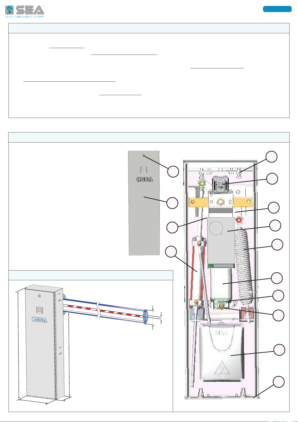
SPRINT is an high speed hydraulic barrier for intensive application, designed for arms up to 6 m
All models are IRREVERSIBLE, to allow a perfect and safe closing of the arm
The barrier is equipped with a MANUAL RELEASE SYSTEM - placed inside the barrier housing - which allows
manual opening and closing in the event of a power outage.
SPRINT is also equipped with an electronic inversion device via ABSOLUTE ENCODER, which makes it
safe and reliable and allows to comply with the Laws in force in the Countries where the barrier is installed.
The ELECTRONIC DECELERATION SYSTEM, combined with the absolute encoder, guarantees total control of
the inertia forces.
The barrier is also equipped with BY-PASS VALVES which allows to adjust the thrust force and thus ensure
anti-crushing safety.
The housing is made of cataphoresis treated steel and painted in polyester for outdoor use, for excellent
resistance to atmospheric agents (the casing is also available in STAINLESS STEEL, upon request)
International registered trademark n. 804888
ENGLISH
1
2
3
5
13
4*
6
11
7
9
10
8
14
1 - ADJUSTABLE MECHANICAL STOPS
2 - ABSOLUTE ENCODER
3 - GALVANIZED STEEL ROCKER ARM
4 - SWITCHING (ONLY ON SPRINT «BR») *
5 - BALANCING SPRING
6 - HYDRAULIC UNIT
7 - BY-PASS VALVES
8 - MOTOR RELEASE SCREW
9 - BOX WITH ELECTRONIC CONTROL UNIT
10 - GALVANIZED STEEL FOUNDATION PLATE
11 - PISTON
12 - BREATHER CAP (SEE CHAPTER 10)
13 - CASING DOOR
14 - LOCK WITH DIN KEY
DIMENSIONS (mm)
Fig. 1
Fig. 2
1003
310 164
830
12
96
56
13
SPRINT (1 L)
SPRINT (2 L) SPRINT IV
230V (±5%) 50/60 Hz
220 W 270 W 250 W 220 W
36Vac
12,5 µF 6,3µF
-
-
75%
1430 rpm
-20°C +55°C
130°C
51 Kg 52 Kg
6 m
IP 55
SPRINT FAST SPRINT BR 36V
230V
1 A 1,1 A
1,2 A
12,5 µF
90%
1 L 2 L 3 L 1,5 L
10 s 8 s 3 s ADJUSTABLE (4 - 10 seconds)
GATE 1 DG
UNIGATE FV INVERTER
3
4
5
6
LIGHT -TH
LIGHT -TH
LIGHT -TH
LIGHT -TH
4
5
7
8
GREEN
BLUE
PINK
VIOLET
5
6,5
8
10
16400010R1
16400015R1
16400026R1
16400027R1
6,5
7
8
8,5
ARM
TYPE
MINIMUM
OPENING TIME (s)
SPRING END-ROD
JOINT COLOR
DEFAULT
OPENING TIME (s)
ARM
LENGTH (m)
ARM LENGTH (m)
SPRING WIRE
DIAMETER (mm)
SPRING
CODE
260 W
-
-
UNIGATE BR 36V
2300 rpm
ARMS SPEED CHART (SPRINT IV AND SPRINT BR ONLY)
The usage rate is valid only if all the arm length parameters and the respective speeds are respected;
refer to this table and to those below
Speed setting must respect the minimum value indicated in the «Minimum Opening Time» column
which varies according to the arm length; DO NOT set values lower than the minimum times indicated
TECHNICAL DATA
POWER SUPPLY
HYDRAULIC UNIT
POWER
ABSORPTION
START CAPACITOR
MOTOR ROTATION SPEED
USAGE RATE
OPERATING TEMPERATURE
THERMAL PROTECTION
OPERATOR WEIGHT
OIL TANK CAPACITY
PROTECTION CLASS
OPENING/CLOSING TIME
MAX. ARM LENGTH
ELECTRONIC CONTROL UNIT
SPRING END-ROD JOINT COLOR
SPRING WIRE DIAMETER (mm) SPRING CODE
SPRINGS FOR «LIGHT-TH» ARMS
2
2,5
3
3,5
4
4,5
5
6
5,5
6,5
6,5
7
7
8
8
8,5
16400005
16400010R1
16400010R1
16400015R1
16400015R1
16400026R1
16400026R1
16400027R1
RED
GREEN
GREEN
BLUE
BLUE
PINK
PINK
VIOLET
In case of FOLDING ARM, set the control unit on 6 meters (menu 11) even if the maximum length of
the folding arm is 4 meters!
The indicated usage rate is valid only for the first operating hour and at a 20°C temperature
International registered trademark n. 804888
ENGLISH

14
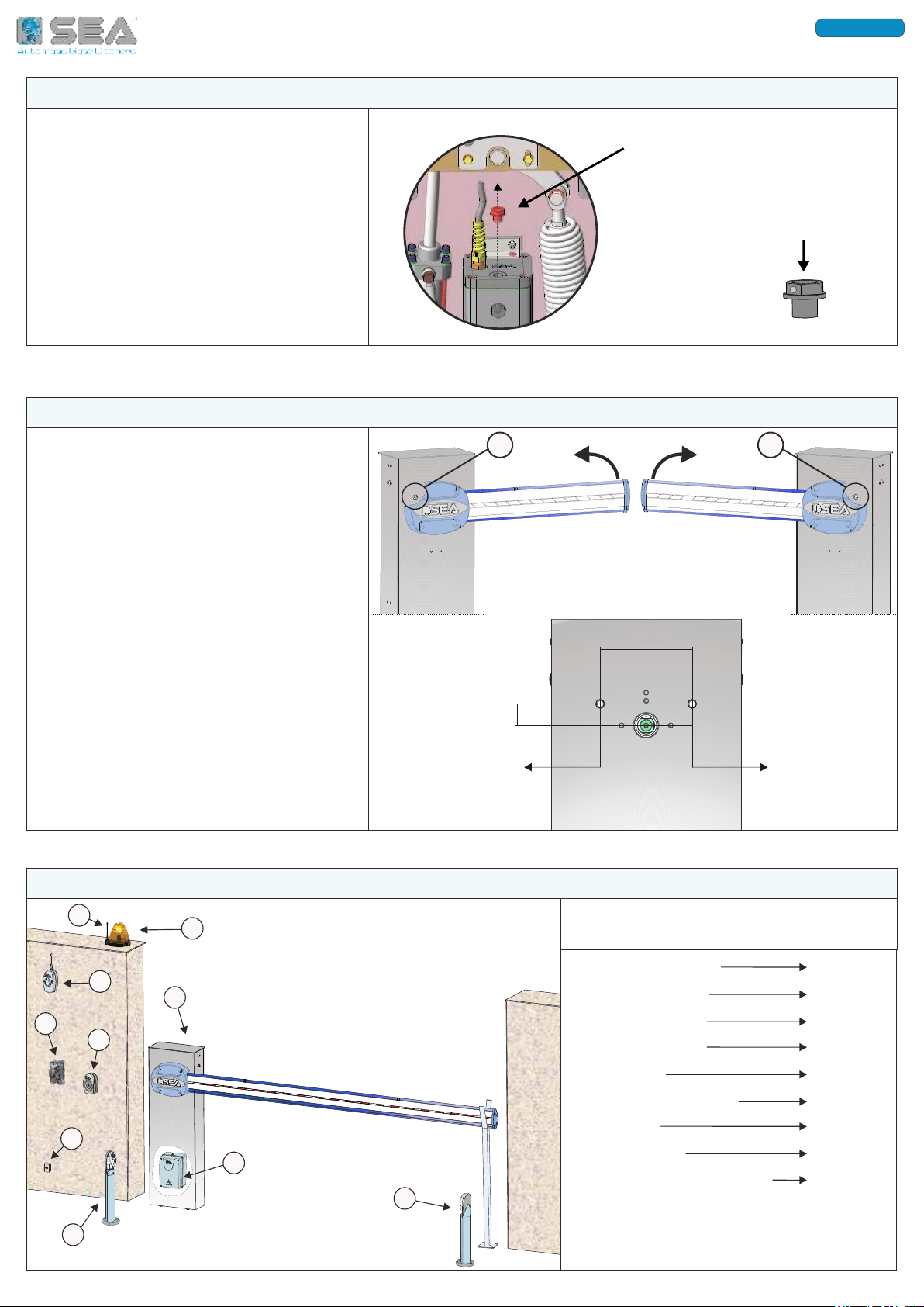
BALANCING
SPRING
ON THE LEFT
1 - LEFT OR RIGHT HAND ARM ARRANGEMENT
The SPRINT barrier can be installed
either for left or right-hand opening
The opening direction depends on the
position of the balancing spring - see
chapter 4:
If the spring is left-hand installed, the arm
opens to the left;
If the spring is right-hand installed, the
arm opens to the right;
To install the foundation plate it is necessary to:
2.1. Prepare a concrete slab according to the
dimensions shown in Fig. 4;
The anchor bolts must be concreted inside the slab.
The foundation plate must be fixed on the anchor
bolts and concreted on the slab
IF ALLOWED BY THE STRUCTURE, IT IS RECOMMENDED
TO LIFT THE FOUNDATION PLATE OF ABOUT 50mm FROM
THE GROUND, TO AVOID WATER PUDDLING.
2.2. Insert the flexible plastic pipe (Ø 30 mm at least)
for the electric cables into the special hole of the plate
2.3. Make sure that the plate is perfectly leveled and
that the anchor bolts come out of the plate for 30 mm,
as shown in Fig. 5
2.4. Fill up the excavation using «R425» concrete;
carefully level the plate on the concrete.
ELECTRIC
CABLES
PIPE
AS IN
FIG. 4
300
500
500
PLINTH
DIMENSIONS IN mm
30
ANCHOR
BOLTS
LEFT-HAND
OPENING
BALANCING
SPRING
ON THE RIGHT
RIGHT-HAND
OPENING
3 - INSTALLATION OF THE BARRIER ON THE FOUNDATION PLATE
3.1. Place the barrier housing on the
foundation plate by matching the base
holes with the anchor bolts coming out of
the plate
3.2. Make sure that the electric cables pipe
has perfectly passed through the large hole
at the base of the barrier housing
3.3. Fix the barrier housing to the
foundation plate using the nuts and
washers provided - Fig. 6 and Fig. 7
FIXING
NUTS AND
WASHERS
HOLE FOR ELECTRIC
CABLES PIPE
Fig. 3
Fig. 4
Fig. 5
Fig. 7
Fig. 6
30 mm
2 - INSTALLATION OF THE FOUNDATION PLATE
International registered trademark n. 804888
ENGLISH

15
4 - LEFT OR RIGHT HAND INSTALLATION OF THE PISTON AND SPRING
360°
ROTATE THE PISTON
ON ITSELF TO
RELEASE IT FROM
PIPES AND CHANGE
ITS POSITION
SPRINT barrier is supplied with left-hand opening arm as standard; it is possible to change the opening
direction by moving both the piston and the balancing spring.
4.1. Before carrying out the moving operation, release the operator - see chapter 13 - and, on the hydraulic
unit, LOOSEN THE TWO FITTINGS OF THE HYDRAULIC PIPES BY HALF A TURN (pipes connecting hydraulic unit to
the piston) to simplify the piston rotation.
Be careful not to choke the hydraulic pipes! (not visible in the figures!)
4.2. CHANGE OF THE OPENING DIRECTION - (RIGHT-HAND OPENING)
- unscrew and pull out the balancing spring - Fig. 11
- unscrew the hydraulic piston - Fig. 8, move it gently from its position by rotating on itself 360° - Fig. 9 - to
release it from the hydraulic pipes and prevent them from intertwining, then place the piston on the opposite
side of the barrier and tighten with the fixing screws - Fig. 10
- lubricate the piston rod-end spherical bearing with DIN 51502 KP 2 N-20 - K 2 K-20 grease
- place the balancing spring on the opposite side of the barrier, greasing the parts indicated in Fig. 12
4.3. In case of ordinary replacement of the spring, according to the barrier opening direction, disassemble
the old spring and reassemble the new one following the tightening instructions in Fig. 11 or in Fig. 12
LEFT-HAND
SPRING MOUNTING
FOR LEFT-HAND
OPENING ARM
W ,
(DIN 51502 KP 2 N-20 - K 2 K-20)
-
Fig. 8 Fig. 10
Fig. 12
Fig. 11
Fig. 9
RIGHT-HAND
SPRING MOUNTING
FOR RIGHT-HAND
OPENING ARM
International registered trademark n. 804888
ENGLISH

16
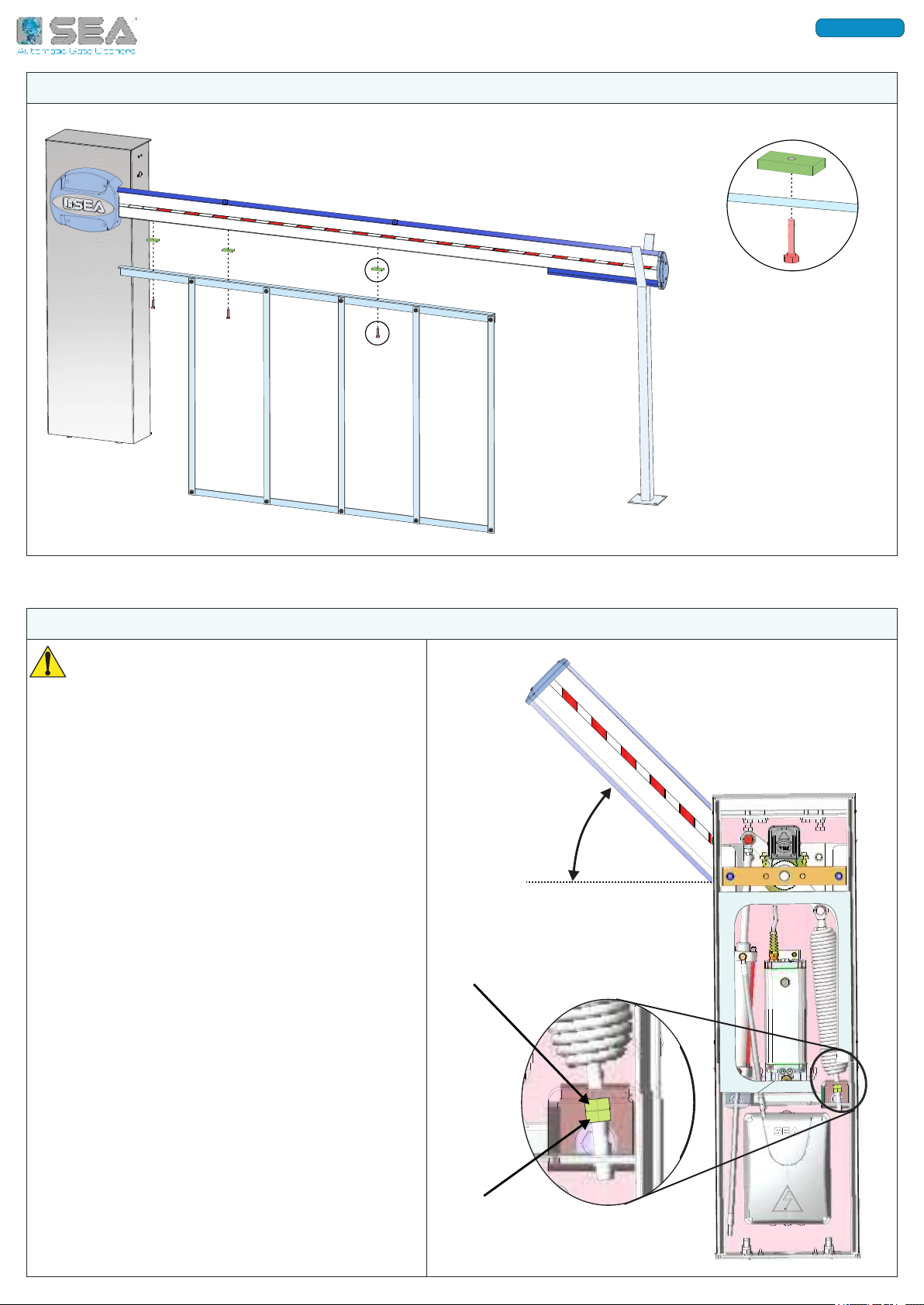
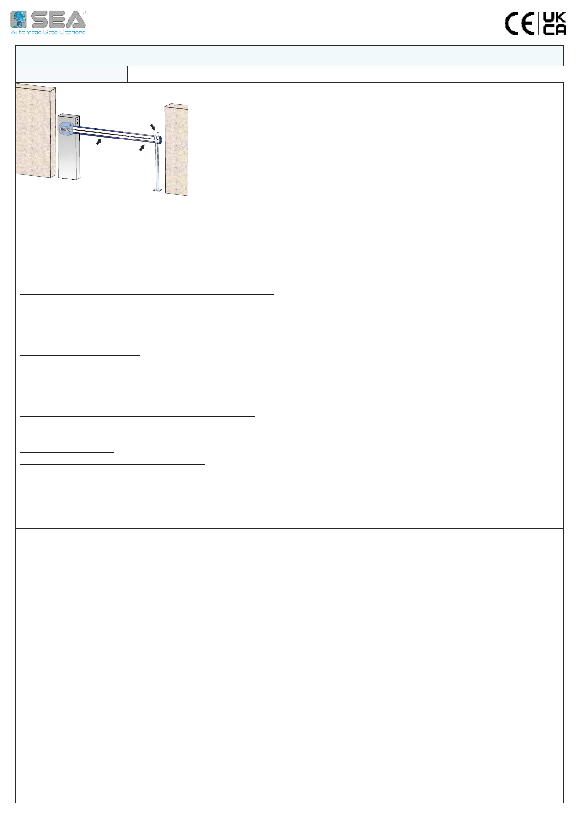
5 - ARM INSTALLATION ON THE BARRIER
A
B
C
D
E
A - ARM FIXING BRACKET
5 mm
B - ANTI-BLUNT RUBBER PROFILE
C - PLASTIC PROFILE FOR LED INSERTION
D - JOINT FOR PLASTIC PROFILE MODULES
E - PLASTIC PROFILE FOR LED INSERTION
For arms longer than 4 meters, it is recommended to install the fork support on the ground (to be
installed at the end of the arm) or to install the folding support (to be installed on the arm)
The «LIGHT TH» arm for SPRINT barrier is supplied in a single module for lengths up to 3 meters, and in two
modules «FIX» + «MB» with joint, for lengths over 3 meters.
For the assembly of the modules, please refer to the arm technical instructions.
5.1. I L (L )
The plastic profile must be mounted on the upper side of the arm;
Insert the first module of the plastic profile «C» in the guide up to the edge of the arm fixing bracket «A»;
Insert the joint «D» followed by the next plastic profile module «E» - repeat for the following modules, each
spaced out by the joint, until the end of the arm; cut out the exceeding module, if necessary.
5.2. I -
The anti-blunt rubber profile must be mounted on the lower side of the arm;
Insert the rubber profile «B» in the guide, sliding up to the edge of the arm fixing bracket «A»;
CUT OUT THE EXCEEDING RUBBER PROFILE MAKING SURE IT COMES OUT OF THE ARM FOR 5 mm - Fig. 13a
Fig. 13
Fig. 13a
International registered trademark n. 804888
ENGLISH
17
6 - SKIRT INSTALLATION (OPTIONAL)
Fig. 14
Fig. 15
7 - ARM BALANCING OPERATION
45°
SPRING-TENSIONER
NUT
TIGHTENING
COUNTER-NUT
For the correct balancing of the arm, it is
recommended to unscrew the piston from
the rocker arm, as shown in CHAPTER 4 - Fig.
8 or Fig. 10
7.1. Release the arm using the manual release
- chapter 13 - in order to move it manually
7.2. Place the arm halfway, approximately 45°
7.3. Tighten or loosen the spring-tensioner nut
until the spring counter-balances the weight of
the arm placed at 45°;
The optimal balancing position is when the arm
stays in the position shown in Fig. 15
7.4. Once the arm has been balanced, lock
the spring-tensioner nut by tightening the
counter-nut.
7.5. Re-lock the arm as shown in chapter 13
International registered trademark n. 804888
ENGLISH
18
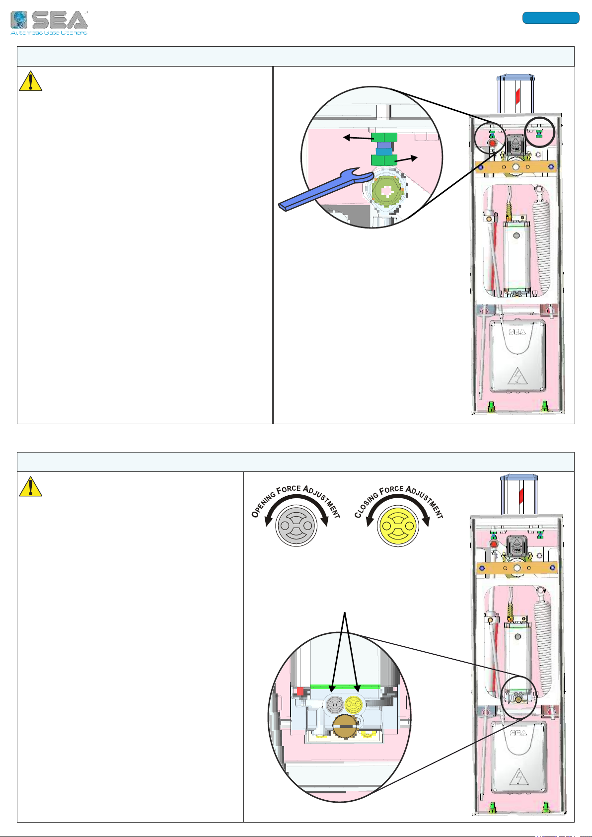
8 - ARM LEVELING
BY-PASS
VALVES
Carry on the following procedure only if
the arm does not stay perfectly horizontal
(in closing) or vertical (in opening) at the end
of its stroke
8.1. Release the arm using the manual release
- chapter 13 - in order to move it manually
8.2. Loosen the nut «B»
8.3. Tighten or loosen the screw «A» until the
arm gets in vertical position in opening and in
horizontal position in closing;
8.4. Once a perfect leveling has been achieved,
lock the screw «A» by tightening the nut «B»
8.5. Re-lock the arm as shown in chapter 13
9 - ADJUSTMENT OF THE THRUST FORCE (BY-PASS VALVES)
The SPRINT barrier is factory set to
a force of 15 KgF in order to ensure
the anti-crushing safety, so it is
recommended to modify this setting
only in case of absolute need!
9.1. If necessary, adjust the thrust force of
the barrier through the By-Pass valves
placed on the front side of the hydraulic
unit - Fig. 17
- Turn clockwise to increase the force;
- Turn counter-clockwise to decrease the
force;
A
B
Fig. 16
Fig. 17
+
-
YELLOW
+
-
GREY
International registered trademark n. 804888
ENGLISH
19
Fig. 19a
11.1. The Fig. 19 shows the drilling holes
diagram for the passage of the power
cables of the barrier lights;
11.2. If the arm is left-hand installed - Fig.
19a, then use hole «A» - Fig. 19
11.3. If the arm is right-hand installed -
Fig. 19b, then use hole «B» - Fig. 19
A
A
142
49
Ø 10 mm
B
B
Ø 10 mm
Fig. 19b
Fig. 19
11 - DRILLING HOLES DIAGRAM FOR LED LIGHTS CABLES PASSAGE
1) BARRIER (MOTOR)
2) PHOTOCELL TX
3) PHOTOCELL RX
4) FLASHING LAMP
5) ANTENNA
6) EXTERNAL RECEIVER
7) KEYPAD
8) KEY-BUTTON
9) DIFFERENTIAL 16A/30mA
10) CONTROL UNIT BOX
RECOMMENDED CABLES NUMBER AND SECTION
FOR WIRINGS ON CONTROL UNIT
* Increase the cable section in case of high
distance from the control unit
Example of barrier and accessories
installation
4 X 1,5
2 X 0,5
4 X 0,5
2 X 0,5
4 X 0,5
4 X 0,5
4 X 0,5
3 X 1,5 *
1
2
3
4
5
6
78
9
10
Fig. 20
1 X RG58
12 - ELECTRIC WIRINGS
10 - BREATHER CAP REPLACEMENT
10.1. Before starting the barrier, remove
the red transport cap and replace it with
the black one supplied and equipped with
the airhole;
The cap is on the top of the hydraulic unit
- Fig. 18
On SPRINT BR model the cap is hidden
behind the switching, so pass the hand
behind the metal support to unscrew the
cap. Fig. 18
REPLACE IT
WITH THE BLACK
BREATHER CAP
REMOVE THE RED
TRANSPORT CAP
International registered trademark n. 804888
ENGLISH

20
LUBRICATE THE SPRING AND PISTON ROD-END SPHERICAL BEARINGS ON THE ROCKER ARM
CHECK THE CONDITION AND THE CORRECT OPERATION OF THE BALANCING SPRING
CHECK THE CORRECT OPERATION OF THE RELEASE SYSTEM
CHECK ALL THE FASTENING SCREWS (ARM, ROCKER ARM AND HOUSING FASTENING SCREWS)
CHECK THE CONDITION OF THE ELECTRIC CABLES
CHECK THE CORRECT OPERATION OF THE BACK-UP BATTERIES (IF INSTALLED)
13.1. TO RELEASE THE BARRIER
- Open the barrier housing door, using the special key supplied - Fig. 21
- Turn the release screw 180° counter-clockwise with a screwdriver (the screw is on the front side of the
hydraulic unit) - Fig. 22
- Manually move the arm
13.2. TO LOCK THE BARRIER
- Turn the release screw clockwise with the screwdriver, up to it stops
- Lock the barrier housing door
LOCK
RELEASE
OPEN THE
HOUSING DOOR
RELEASE
SCREW
ON THE
HYDRAULIC
UNIT
Fig. 21
Fig. 22
PART FOR BOTH INSTALLER AND END-USER
ALL THE UNLOCKING AND LOCKING OPERATIONS AND ALL PERIODIC MAINTENANCE OPERATIONS
MUST BE CARRIED OUT IN ABSENCE OF POWER SUPPLY!
13 - RELEASE SYSTEM
14 - PERIODIC MAINTENANCE - FOR INSTALLERS ONLY!
ANNUAL
ANNUAL
ANNUAL
ANNUAL
ANNUAL
ANNUAL
ALL OPERATIONS MUST BE CARRIED OUT EXCLUSIVELY BY AN AUTHORIZED INSTALLER
ALL OPERATIONS MUST BE CARRIED OUT IN ABSENCE OF POWER SUPPLY
International registered trademark n. 804888
ENGLISH
21
International registered trademark n. 804888
GENERAL NOTICE
RISK EXAMINATION: The points pointed by arrows are potentially dangerous. The
installer must take a thorough risk examination to prevent crushing, conveying,
cutting, grappling, trapping so as to guarantee a safe installation for people, things
and animals (Re. Laws in force in the Country where installation has been made). As
for misunderstandings that may arise refer to your area distributor or call our help
desk. These instructions are part of the device and must be kept in a well known
place. The installer shall follow the provided instructions thoroughly. SEA products
must only be used to automate doors, gates and wings. Any initiative taken without
SEA explicit authorization will preserve the manufacturer from whatsoever respon-
sibility. The installer shall provide warning notices on not assessable further risks. SEA in its relentless aim to improve the
products, is allowed to make whatsoever adjustment without giving notice. This doesn’t oblige SEA to upgrade the past
production. SEA can not be deemed responsible for any damage or accident caused by product breaking, being damages or
accidents due to a failure to comply with the instructions herein. The guarantee will be void and the manufacturer
responsibility will be nullified if SEA original spare parts are not being used. The electrical installation shall be carried out by a
professional technician who will release documentation as requested by the laws in force. Packaging materials such as
plastic bags, foam polystyrene, nails etc must be kept out of children’s reach as dangers may arise.
INITIAL TEST AND STARTING OF THE AUTOMATION: After having completed the necessary operations for a correct
installation of the product and after having evaluated all the risks which could arise in any installation, it is necessary to test
the automation to guarantee the maximum safety and to guarantee that the Laws in force are fully respected. The
first Start must be executed according to the rule EN 12445 which establishes the methods of tests for checking the gate
automation respecting the limits established by the rule EN 12453
SAFETY PRECAUTIONS: All electrical works should comply with the current regulations. A 16A/0,030 differential switch
must be used. Separate the source cables (operators, power supply) and command cables (photocells, push-buttons,
etc). Be sure the entire system is properly grounded. Always run cables in separate ducts to prevent interferences
INTENDED USE: The operator has been designed to be used as access automatic barrier only
SPARE PARTS: Send request for spare parts to: SEA S.p.A. - Teramo - ITALY - www.seateam.com
SAFETY AND ENVIRONMENTAL COMPATIBILITY: Don’t waste product packing materials and/or circuits
STORAGE: T = -30°C/+60°C ; Humidity = min. 5% / max. 90% (without condensation); Materials must be properly
packaged, handled with care and with appropriate vehicles
WARRANTY LIMITS - see the sales conditions
MAINTENANCE AND DECOMMISSION: must only be carried out by specialized and authorized personnel
THE MANUFACTURER CAN NOT BE DEEMED RESPONSIBLE FOR ANY DAMAGE OR INJURY CAUSED BY
IMPROPER USE OF THIS PRODUCT
SEA S.p.A. reserves the right to make any required modification or change to the products and/or to this manual without any
advanced notice obligation.
1. Read carefully these instructions before beginning to install the product. Store these instructions for future reference
2. Don’t waste product packaging materials and /or circuits
3. This product was designed and built strictly for the use indicated in this documentation. Any other use, not expressly indicated here, could compromise the good
condition/operation of the product and/or be a source of danger. SEA S.p.A. declines all liability caused by improper use or different use in respect to the intended one.
4. The mechanical parts must comply with Directives: Machine Regulation 2006/42/CE and following adjustments, Low Tension (2006/95/CE), Electromagnetic
Consistency (2004/108/CE); Installation must respect Directives: EN12453 and EN12445.
5. Do not install the equipment in an explosive atmosphere.
6. SEA is not responsible for failure to observe Good Techniques in the construction of the locking elements to motorize or for any deformation that may occur during use
7. Before attempting any job on the system, cut out electrical power and disconnect the batteries. Be sure that the grounding system is perfectly constructed, and
connect to it the metal parts of the gate
8. Use of the indicator-light is recommended for every system, as well as a warning sign well-fixed to the frame structure.
9. SEA declines all liability concerning the automated system safety and efficiency, if components used are not produced by SEA
10. For maintenance, strictly use original parts by SEA.
11. Do not modify in any way the components of the automated system.
12. The installer shall supply all information concerning the system manual functioning in case of emergency and shall hand over to the user the warnings handbook
supplied with the product.
13. Do not allow children or adults to stay near the product while it is operating. The application cannot be used by children, by people with reduced physical, mental or
sensorial capacity or by people without experience or necessary training. Keep remote controls or other pulse generators away from children, to prevent involuntary
activation of the system.
14. Transit through the leaves is allowed only when the gate is fully open.
15. The User must not attempt to repair or to take direct action on the system and must solely contact qualified SEA personnel or SEA service centers. The User can apply
only the manual function of emergency.
16. The power cables maximum length between the central engine and motors should not be greater than 10 m. Use cables with 2,5 mm2 section. Use double insulation
cable (cable sheath) to the immediate vicinity of the terminals, in particular for the 230V cable. Keep an adequate distance (at least 2.5 mm in air), between the
conductors in low voltage (230V) and the conductors in safety low voltage (SELV) or use an appropriate sheath that provides extra insulation having a thickness of 1 mm
PART FOR BOTH INSTALLER AND END-USER

SEA S.p.A.
Zona Industriale Sant’Atto - 64100 - Teramo - ITALY
Tel. +39 0 861 588341 r.a. Fax +39 0 861 588344
www.seateam.com
International registered trademark n. 804888
Other manuals for Sprint
1
This manual suits for next models
3
Table of contents
Other SEA Automatic Barrier manuals


X Series user manual")


