SEA STORM 24V User manual

STORM 24V
®
International registered trademark n. 2.777.971
web site: www.sea-usa.com
e-mail: [email protected]
SEA USA Inc.
10850 N.W. 21st unit 160 DORAL MIAMI
Florida (FL) 33172
Phone:++1-305.594.1151 Fax: ++1-305.594.7325
Toll Free: 800.689.4716
Rev. 00 - 11.2010Code 67411125

GENERAL SAFETY REGULATIONS FOR THE INSTALLER
• The installer has to read and understand the functioning of this operator system, its safety features and knowing the manual function in case of emergency.
• Do not modify in any way the automated system’s components. SEA USA Inc. declines all liability concerning the automated system’s security and efficiency if
the used components are not produced by SEAUSAInc. For maintenance, strictly use original SEAUSA Inc. spare parts.
• The installer shall supply the user with all information concerning the proper operation of the product, the system’s manual functioning in case of emergency and
shall hand over to the user the warnings handbook supplied with the product.
• SEA USA Inc. recommends the system to have reversing sensor (encoder) on the drive shaft of the motor. In case of swing/linear/in-ground hydraulic
operators/barriers, SEA USA Inc. recommends to install the SAFETY GATE as an additional reversing sensor. Reversing devices are required to prevent the
system from closing on vehicular traffic and/or help to prevent injuries to pedestrians.
• It is recommended to use indicator-lights as well as warning signs for every system. Both should be visible on each side of the gate and well fixed on the frame
structure.
• Do not leave packing materials (plastic, polystyrene, etc.) within children’s reach, as they are potential sources of danger.
• For products having an emergency release, it is recommended to use it only when the gate/barrier is closed.
• Remove all locks connected to the gates before installing the operator.
• Locate the control button: (a) within sight of door, (b) at minimum height of 5 feet so that small children are not able to reach it, and (c) away from all moving parts
of the door.
• Install entrapment Warning Label next to the control button in a prominent location.Attach marking next to the emegency release.
• Do not employ for any reason automatic closing devices (such as timer, loop sensors, or similar), and do not connect any other activation devices.
GENERAL SAFETY REGULATION FOR THE USER
• Sea strongly recommends to follow these instructions literally to prevent very serious damages to persons. This product was designed and built strictly for the
use indicated in this documentation. Any other use, not expressly indicated here, could compromise the good condition/operation of the product and/or be a
source of danger. SEAUSA Inc. declines all liability caused by improper use or different use in respect to the intended one.
• Only qualified personnel can install, repair and periodically check this equipment.
• The User must not attempt to repair or to take direct action on the system and must solely contact qualified SEA personnel or SEA service centres. User can
apply only the emergency manual function.
• The system has been designed for the control of vehicular traffic only. Pedestrians or bicycles must have a separate access opening.
• Do not allow children or adults to stay near the product while it is operating. The application cannot be used by children, by people with reduced physical, mental
or sensorial capacity, or by people without experience or necessary training. Keep remote controls or other pulse generators away from children to prevent
involuntary activation of the system.
• Transit through the leaves or barrier is allowed only when the gate/barrier is fully open. Operate system only if it is fully visible, and free of obstructions.
• For products having an emergency release use it only when the door/barrier is closed.
ELECTRICAL CONNECTIONS - SAFETY INSTRUCTIONS
• Disconnect the battery back up, if included, before disconnecting main power supply.
•Always disconnect power supply during installation or servicing of the product.
•All electrical connections from the control panel’s to the operator’s must be made in a waterproof junction box.
• The system requires a separate power supply circuit. Check that the main power supply circuit breakers are separated, intended solely for this equipment and
rated for 15AMPS. Visually check that the circuit breakers are in OFF position and mark the circuit breakers USED prior to installation.
• Permanent wiring must be used and installed to the operator as required by local electrical codes and It is recommended to do by a licensed electrician.
It is also recommended to check the local building code requirements before making any type of wiring to be sure that all wirings comply with them. Local building
codes will take precedence. It is recommended to use different colours for all wirings’codes.
• Distance for low voltage control wires, i.e., open input, single leaf, open input and stop input, can run up to 3000 feet with 18AWG wire. Low voltage controls and
communication wirings must all be separated by a minimum of 1 foot from high voltage power wiring and in a separate conduit.
GROUNDING
• Good grounding and proper surge suppression are an integral part of proper installation for all operator systems. One or all of the followings may require surge
suppressors: high voltage power lines, low voltage power lines, telephone lines, data lines, low voltage control lines and loops. Quantity of surge suppression
requires depends on susceptibility of the area to lightning and power surges. Good grounding is essential to realize maximum protection.
• If the circuit breaker box is located close to the gate/barrier operator system, for example, in a guardhouse, then the ground from that circuit can be used to
ground the gate operator system. Eliminate all 90° bends in ground wires and keep a minimum distance of three feet between the surge suppressor and the
equipment to protect.
• If the power source or circuit breaker box is not located close to the operator system, an Isolated Ground Zone (IGZ) must be created. An IGZ is an imaginary
circle drawn around the operator system. An IGZ can also be created, if the circuit breaker box is located close to the operator system. The operator system not
only includes the operator and control panel, but all accessories and devices associated with it at that controlled entry point. This includes loop detectors, card
readers, digital entries, telephone entries, any device that has or requires grounding and all the surge suppressors. The ground bus is a common ground point
called Single Point Ground (SPG). It is used to bond all the equipments and devices grounded in the IGZ together. The SPG is very important because it helps to
eliminate different ground potentials that can be present on the equipment and that could cause damages even with surge suppressors.
• Do not use or connect the ground wire coming from the circuit breaker box. By using an Isolated Ground Zone, you have to separate the operator system from
the house or building ground. This eliminates ground potentials. It is recommended the ground bus to be located in a separate NEMAtype enclosure. All grounds
will be tied to this ground bus.
• Equipment ground wire should be of minimum 12AWG. The main ground wire from the bus bar to the ground rod should be an 8 or 6AWG copper wire.
Ground rod should be minimum 10 feet in length, (length depends on local soil conditions).
• For more information, regarding good grounding practices check: National Electric Code art. 250; IEEE Emerald Book, standard 100; International Association
of Electric Inspectors.
• Where possible, install the opener control 7 feet or more above the floor. For products having an emergency release, mount the emergency release 6 feet above
the floor.
SEA USA Inc.
10850 N.W. 21st unit 160 DORAL MIAMI
Florida (FL) 33172
Phone:++1-305.594.1151
Fax: ++1-305.594.7325
Toll Free: 800.689.4716
®
International registered trademark n. 2.777.971
Storm 24V
Rev. 00 - 11.2010Code 674111252

INSTALLATION WARNINGS
• For gate operators: install only when
A. The operator is appropriate for the gate’s construction and usage Class.
B. All opening spaces on the wall of the horizontal slide gate are guarded or screened from the bottom of the gate to a minimum of 4
feet (1m) above the ground so that it could be possible to keep on the entire surface of the wall a minimum distance of 2-1/4 (57,15mm) inches from the
gate and the wall on which the gate runs.
C.All exposed pinch points are eliminated or guarded
D. Guarding is supplied for exposed rollers.
E. Check if the gate works freely in both directions before installing the gate operator system. Any necessary repair to the gate must be done
before installing the equipment. Swinging gate shall not open into public access areas.
• The operator systems must be installed in a proper place to prevent contacts with adjacent structures in opening and closing. Watch out to install the system so
that users could have full view of the area.
• For operators using non-contact sensors:
A. See instructions on the placement of non-contact sensors for each Type of application.
B. Watch out to reduce the risk of nuisance tripping of the sensor.
C. One or more non-contact sensors shall be located where the risk of entrapment or obstruction exists, such as the perimeter reachable by a moving
gate or barrier.
• For operators utilizing contact sensors:
A. One or more contact sensors must be located where the risk of entrapment or obstruction exists, such as the operators’ edges. They
should be installed both inside and outside the operator’s edge.
B. A hardwired contact sensor must be installed, watching out to arrange its wiring so that the communication between the sensor and the
operator should not be subjected to mechanical damage.
C. A wireless contact sensor such as a radio frequency (RF) signal transmitter must be located where the signal’s transmission cannot be
obstructed by structures or natural landscaping.
• Controls should be far enough from the gate or barrier so that the user is prevented from coming in contact with them while operating the controls. Controls are
intended to be used to reset an operator after 2 sequential activations of the entrapment protection device and must be located in the line-of-sight of the outdoor.
Install a security feature If controls are easily accessible, to prevent unauthorized use.
AFTER INSTALLATION
• Check that: the open and close force are properly adjusted; the piston does not bottom out in either direction, the breather screws have been removed, the
positive stops used are sufficient for stopping the gate properly, all the pinch points and potential entrapment areas are reduced.
• Check and test all reversing devices.
• The installer should instruct user on the operator system’s proper operation. They should together review the basic functions of the reversing devices and how to
periodically test them. Reversing devices include one or more of the followings: reversing loops, photocells, reversing edges, etc. The installer has to instruct
user on how to remove the operator system from service, on shutting power off on the service panel and how to use the operator system manually.
GENERAL ENTRAPMENT PROVISIONS
A vehicular operator must be installed with one independent primary and one independent secondary means at least to protect against entrapment
(see Table A):
Note: The same type of device shall not be utilized for both the primary and secondary entrapment protection means. The use of a single device to cover both
the opening and closing directions is in accordance with the requirements; however, a single device is not required to cover both directions. A combination of
one Type B1 for one direction and one Type B2 for the other direction is the equivalent of one device, for the purpose of complying with the requirements of
either the primary or secondary entrapment protection means.
Entrapment protection types
TypeA: Inherent entrapment sensing system.
Type B1: Provision for connection of a non-contact sensor (photoelectric or equivalent).
Type B2: Provision for connection of a contact sensor (edge device or equivalent).
Type C: Inherent adjustable clutch or pressure relief device.
Type D: Provision for connection of an actuating device requiring continuous pressure to maintain opening or closing motion of the gate.
Type E: An inherent audio alarm.
CLASS OF OPERATORS
RESIDENTIAL VEHICULAR GATE OPERATOR - CLASS I - A vehicular operator (or system) intended for use in a home of one-to four, single-family dwelling, or
a garage or parking area associated therewith.
COMMERCIAL/GENERAL ACCESS VEHICULAR OPERATOR - CLASS II - A vehicular operator (or system) intended for use in a commercial location or
building such as multi-family housing unit (five or more single family units), hotel, garage, retail store, or other building servicing the public.
INDUSTRIAL/LIMITED ACCESS VEHICULAR OPERATOR - CLASS III - A vehicular operator (or system) intended for use in an industrial location or building
such as a factory or loading dock area or other locations not intended to service the public, in which unauthorized access is prevented via supervision by security
personnel.
SEA USA Inc.
10850 N.W. 21st unit 160 DORAL MIAMI
Florida (FL) 33172
Phone:++1-305.594.1151
Fax: ++1-305.594.7325
Toll Free: 800.689.4716
®
International registered trademark n. 2.777.971
Storm 24V
Rev. 00 - 11.2010Code 67411125 3

SEA USA is glad to congratulate and thank you for
choosing our product. Your choice will allow you to
understand how our factory, according to studies, research
and above all the needs of our customers, wants to gather
technology, reliability and safety together keeping in mind
use and installation easiness.
General characteristics
Storm is an electro-mechanical automation for big carriage entrances (16.40, 19.68,
22.96 feet) The places for fitting are multiple; Storm is ideal for camp entrances,
hospitals, yards, private roads, port and airport entrances, public parking with half-
intensive working cycles. It is provided with an anti-crush device (230 version) that
ensures a strength of max. 33 pound on the beam so to ensure people and things
against accidents. An accurate slowing down system guarantees the total control of
the momentum strength. The manual release makes the beam independent from the
motor-reducer so to allow the manual closing and opening.
The automation consists of :
The cataphoresis and epoxy treated dust painted steel sheet casing protects all mechanical and electric devices from
atmospheric agents. On request it is also possible to receive the casing in stainless steel.
The balancing spring is delivered according to the beam length, inside the beam kit (See spring tab.)
GATE 1 electronic control unit for 230 version and USER 1 24V for 24V version, advanced devices which allow the
programming and control of all working and safety systems.
Motor-reducer with manual release for the manual opening of the beam in case of damages.
Beam in extruded aluminium, available sizes: from 16.40 feet to 24.60 feet.
Mounting plate out of steel sheet coated with zinc.
Balancing wheel in galvanized steel.
1
2
3
4
5
6
7
List of the main parts:
1. Storm Series casing
2. Balancing spring
3. Electronic Control Unit
4. Storm operator
5. Aluminium beam
6. Balancing lever
7. Storm/Vela Ind. mounting plate
11
22
44
55
33
65
47
SEA USA Inc.
10850 N.W. 21st unit 160 DORAL MIAMI
Florida (FL) 33172
Phone:++1-305.594.1151
Fax: ++1-305.594.7325
Toll Free: 800.689.4716
®
International registered trademark n. 2.777.971
Storm 24V
Rev. 00 - 11.2010Code 674111254

Technical data
Voltage supply
Motor tension
Power absorption
Opening time
Max. Beam length
Protection degree
Motor revolutions
Operating temperature
Weight
Manual release
Use frequency
24V
150W
7-9 s
-4°F +131°F
2800 RPM
IP55
183 pound
70%
yes
115 V ± 5% - 50/60 Hz~
24.60 feet with fork / 22.96 feet side fixation
24V Version
Dimensions (inches):
Fig.2
FITTING INSTRUCTIONS
1) Position of spring
Right hand closing barrier Left hand closing barrier
This versatile barrier allows the left or right hand closing
according to your requirements.
If the provided barrier does not close on the desired side it is possible to invert it
following the instructions.
Fig.1
Note: The frequency of use is valid only for the first hour at 20°C room
temperature.
Rectangular beam
Barrier Length
16.40 feet
19.68
22.96
24.60
D. Spring
0.41 in
0.43
0.45
0.49
Fexlible support
yes
yes
yes
yes
Linear beam
Barrier Length
D. Spring Fexlible support
yes
yes
yes
Type of skirt
14,76 feet
18.04
21.32
Barrier Length
D. Spring
Side beam with skirt
15.74
8.38
44.09
6.22
3.03
36.61
16.40 feet
19.68
22.96
16.40 feet
19.68
22.96
SEA USA Inc.
10850 N.W. 21st unit 160 DORAL MIAMI
Florida (FL) 33172
Phone:++1-305.594.1151
Fax: ++1-305.594.7325
Toll Free: 800.689.4716
®
International registered trademark n. 2.777.971
Storm 24V
0.41 in
0.43
0.45
0.43 in
0.45
0.49
Rev. 00 - 11.2010Code 67411125 5

N.B.: The operator comes as shown in Fig.1 (Closing on the right hand side).
Example:
Barrier with right hand closing (Fig.1)
Barrier with left hand closing (Fig. 2)
Before installing the spring check the choice of the barrier, if right or left hand side.
If the barrier is with closing on the left hand side move the connecting rod from the right to the left
hand side as shown in Fig.4 and 5.
N.B.: Before executing this operation release the motor-reducer as shown in Fig.19.
Once exchanged the connecting rod tighten its fixation screw and lubricate with grease (Use DIN
51502 KP 2 N-20 - K 2 K-20 grease).
Tighten
at Max.50 Nm
Spring support
Spring tensioning
bolt
Fig. 3
Mi 39.
n.
0.in
Min. .39 in.
0
Fig. 6
Fig. 4 Fig. 5
Connecting rodConnecting rod
SEA USA Inc.
10850 N.W. 21st unit 160 DORAL MIAMI
Florida (FL) 33172
Phone:++1-305.594.1151
Fax: ++1-305.594.7325
Toll Free: 800.689.4716
®
International registered trademark n. 2.777.971
Storm 24V
Rev. 00 - 11.2010Code 674111256

2) Mounting of the spring
Insert the spring in to the carter as shown in Fig.7.
Fig. 7
Lubrication
with grease
during mounting
3) Mounting plate fixing
- Dig a hole 31.49x23.62x15.74 inches.
- Widen the foundation plate clamps at 60° (Fig. 8)
- Fill the hole with R425 concrete and place the foundation plate
as in Fig. 8.
- Level the plate with care.
* The plate has got a central hole for electric wiring so before
filling the hole with concrete put an elettric wire sheathing on the
hole.
Concrete
Fondation plate
to be levelled
Wire sheathing
Clamps 60°~
Fig. 8
15.74
31.49
SEA USA Inc.
10850 N.W. 21st unit 160 DORAL MIAMI
Florida (FL) 33172
Phone:++1-305.594.1151
Fax: ++1-305.594.7325
Toll Free: 800.689.4716
®
International registered trademark n. 2.777.971
Storm 24V
Rev. 00 - 11.2010Code 67411125 7

4) Fixing the column on the foundation plate
- Place the column so that the holes at the base correspond to the screws that emerge from the foundation plate.
- Make sure that the wire sheathing is fixed on the big central hole at the base of the column.
- Tighten the column to the foundation plate screwing the provided nuts and bolts with care.
Fixing nuts
& bolts
Hole for wire
sheathing
Fig. 9
Fig. 10
5) Mounting of the central beam with fork (Fig. 10)
Beam
Nuts and bolts for
beam fixing
SEA USA Inc.
10850 N.W. 21st unit 160 DORAL MIAMI
Florida (FL) 33172
Phone:++1-305.594.1151
Fax: ++1-305.594.7325
Toll Free: 800.689.4716
®
International registered trademark n. 2.777.971
Storm 24V
Rev. 00 - 11.2010Code 674111258

6) Mounting of the beam (Fig. 11)
Fig. 11
SEA USA Inc.
10850 N.W. 21st unit 160 DORAL MIAMI
Florida (FL) 33172
Phone:++1-305.594.1151
Fax: ++1-305.594.7325
Toll Free: 800.689.4716
®
International registered trademark n. 2.777.971
Storm 24V
Rev. 00 - 11.2010Code 67411125 9

7) Mounting of the skirt on the beam
N.B.: The skirt can be installed only on lateral mounted beams.
Fig. 12
Fig. 13
8) Balancing the spring
- Turn the manual release valve anti-clockwise to release the motor/reducer so that the beam can
be opened and closed manually.
-
- Tight or untight the spring adjusting bolt locknut so that the spring reaches a balance point with the
beam at 45° (Fig.14).
-After balancing fix the spring adjusting bolt locknut with the bolt and block the motor/reducer.
9) Barrier power supply
Now it is possible to power supply the barrier.
Place the beam at approx. 45° and execute the balancing with the nuts of Fig.14.
To obtain a correct balancing the beam must be on 45° and the operator must be unlocked.
SEA USA Inc.
10850 N.W. 21st unit 160 DORAL MIAMI
Florida (FL) 33172
Phone:++1-305.594.1151
Fax: ++1-305.594.7325
Toll Free: 800.689.4716
®
International registered trademark n. 2.777.971
Storm 24V
Rev. 00 - 11.2010Code 6741112510

Fig. 14
4°54°5
Fig.15
B
Fig. 16
C
Fig. 17
10) Levelling the beam
Important: This manoeuvre must be executed only if at the end stroke the beam is not in perfectly horizontal position in closing or
in perfectly vertical position in opening.
- Unlock the actuator through the release screw so that the beam opens and closes manually.
- Release the end stroke screws unscrewing the lock nuts on the limit switch (Fig.15).
- Screw or unscrew the end stroke screws so that the beam stays in perfectly vertical position in opening and in perfectly
horizontal position in closing (Fig.15).
-After levelling, fix the end stroke by tightening the lock nuts on the limit switch and block the actuator.
Spring tension
adjusting bolt
Spring bolt
locknut
11) Levelling of the central beam with fork
First extract the screws B, than the screws C (Fig.16). Continue as described in the preceding paragraph.
SEA USA Inc.
10850 N.W. 21st unit 160 DORAL MIAMI
Florida (FL) 33172
Phone:++1-305.594.1151
Fax: ++1-305.594.7325
Toll Free: 800.689.4716
®
International registered trademark n. 2.777.971
Storm 24V
Rev. 00 - 11.2010Code 67411125 11
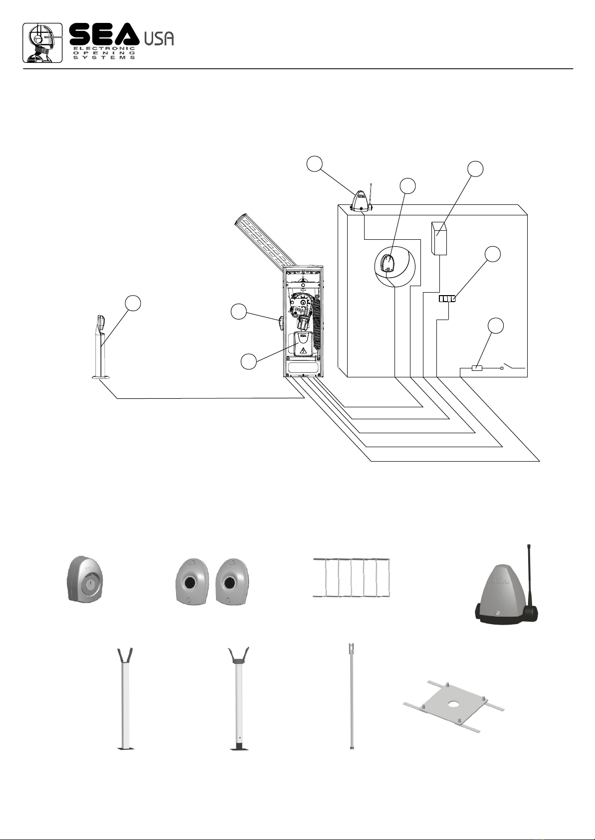
12) Standard installation
In Fig.18 you find the necessary wiring for the barrier installation.
The two numbers placed next to the electric cables show their quantity and section.
Legend:
1) Electronic control unit
2) Photocell (receiver)
3) Photocell (transmitter)
4) Key switch
5) Radio receiver
6) Warning light
7) Push button board
8) Differential switch
Fig.18
11
22
33
44
55
66
77
88
2x1
2x1
2x1 1XRG58
4x1
3x1,5
3x1
PHOTOCELLS SKIRT (ONLY ON SIDE BEAM)
COUNTER PLATE
FOR FORK SUPPORT
KEY SWITCH
WARNING LAMP
13) Accessories for STORM
FIXED FORK
SUPPORT
ADJUSTABLE
FORK SUPPORT
FEXLIBLE SUPPORT
(ONLY BEAM)
SEA USA Inc.
10850 N.W. 21st unit 160 DORAL MIAMI
Florida (FL) 33172
Phone:++1-305.594.1151
Fax: ++1-305.594.7325
Toll Free: 800.689.4716
®
International registered trademark n. 2.777.971
Storm 24V
Rev. 00 - 11.2010Code 6741112512

Fig.19 Fig.20
To the attention of users and technicians
14) Release system
To release operate as follows:
- Open the lid and insert the key
- Turn it clockwise up to the release of the operator.
To re-lock operate as follows:
- Turn the key anti -clockwise until it stops
- Manually move the beam until it re-engages
- Close the lid
To release To relock
PERIODICAL MAINTENANCE
Check the functionality of the release Annually
Lubricate all moving parts Annually
Check the efficiency of the spring (balancing) Annually
Check the beam fixing screws, the balance and the casing Annually
Check the integrity of the connexion cables Annually
All above mentioned operations must be executed exclusively by authorized installers.
SEA USA Inc.
10850 N.W. 21st unit 160 DORAL MIAMI
Florida (FL) 33172
Phone:++1-305.594.1151
Fax: ++1-305.594.7325
Toll Free: 800.689.4716
®
International registered trademark n. 2.777.971
Storm 24V
Rev. 00 - 11.2010Code 67411125 13

GENERAL WARNING: Installation must be realized using parts and accessories approved by SEA. SEA is not
responsible for incorrect installations and/or non-compliance with safety standards according to the law in-force. SEA
is in no way liable for any damages and/or malfunctioning due to using parts and accessories non-compliant with the
UL325 safety standards.
ORDERS: Orders are processed upon approval by SEA. Buyers must confirm orders by sending a written Purchase
Orders to SEA. Purchase Orders are intended as confirmation of orders and binding for the buyer, which accepts SEA
sales condition.
QUOTATION: Quotation and special offers with a non-specified duration expires automatically after 30 days.
PRICES: Prices are based on the Price List in force. Discounts and quotation from Sales Rep. and other selling
branches must be approved by SEA. Prices are F.O.B SEA Warehouse in Miami and do not include shipments costs.
SEAreserves the right to modify the price list at any time and provide notice to its sales network.
PAYMENT: Method of payments and terms are notified by SEAand displayed on the commercial invoice.
DELIVERY: The delivery time on the invoice is not binding and represents an estimated delivery. Shipments costs will
be charged to the buyer and SEA is not responsible for delays and/or damages occurred to the products during
shipment.
COMPLAINS: Complains and/or claims must be notified to SEA within 7 business days after receiving the products.
Claims and complains must be supported by original documents. Customer must contact the factory for instructions
and authorization. Merchandise returned for credit must be current, uninstalled and unused and returned in its original
packaging. Freight must be pre-paid on all authorized returns.
REPAIRS: Repairs and parts are subject to the availability in stock. Shipment of products for repairs must be pre-paid
by the customer. Products shipped without authorization, sender’s details and description of the problems will be
refused. Customers must contact SEAfor instructions.
WARRANTY: for the original buyer only:
Hydraulic and oil-bath motors: 36 months warranty from the date of invoice on manufacturing, assembling and
workmanship defects.
Electro-mechanic motors and electronic control systems: 24 months warranty from the date of invoice on
manufacturing, assembling and workmanship defects.
Lepus and Full Tank Standard model: 60 months warranty from the date of invoice on manufacturing, assembling and
workmanship defects.
No warranty will be recognized for damages due to incorrect installation and/or improper use for which the product was
intended. SEA warranty obligations shall be limited to repair or replace the defective product/parts at SEA option, upon
examination of the products by SEA technical Staff. All replaced parts must remain property of SEA. The warranty
status of the product remains an unquestionable assessment of SEA. Buyer must ship pre-paid defective products.
Products under warranty will be returned pre-paid by SEA. Recognized defects, whatever their nature, will not produce
any responsibility and/or damage claims to SEA USA Inc and SEA s.r.l. Warranty shall not cover any required labor
activities. Warranty will in no case be recognized if alterations and any other changes will be found on products.
Warranty will not cover damages caused by carriers, expendable materials and faults due to improper use with the
products specifications. No indemnities are recognized during repairing and/or replacing of the products under
warranty. SEA USA Inc. and SEA s.r.l. decline any responsibility for damages to person and objects deriving from non-
compliance with safety standards, installation instructions or use of the products sold. It is intended that warranty will be
recognized only on products bought through the SEAauthorized network. Products must be installed by professionals.
No warranty will be recognized if products are installed directly by the final user. Warranty does not apply in case of
unexpected events such as fire, flood, electrical power surge, lightning, vandalism and others.
SEA USA Inc. is not responsible for errors in technical information printed in catalogs and installation
manuals.
SALES CONDITIONS
SEA USA Inc.
10850 N.W. 21st unit 160 DORAL MIAMI
Florida (FL) 33172
Phone:++1-305.594.1151
Fax: ++1-305.594.7325
Toll Free: 800.689.4716
®
International registered trademark n. 2.777.971
Storm 24V
Rev. 00 - 11.2010Code 6741112514


web site: www.sea-usa.com
e-mail: [email protected]
SEA USA Inc.
10850 N.W. 21st unit 160 DORAL MIAMI
Florida (FL) 33172
Phone:++1-305.594.1151 Fax: ++1-305.594.7325
Toll Free: 800.689.4716
®
International registered trademark n. 2.777.971
Table of contents
Other SEA Automatic Barrier manuals


