SEA VERG 24V User manual

VERG 24V BARRIER
General features
VERG 24V is an electro-mechanical barrier (2, 3, 4, 5 m)
recommended for the automation of access points which
require a high opening/closing speed (parking lots,
motorways, airports, etc.) and frequent use features. The
automation includes an anti-crush security system with
adjustable sensitivity, which guarantees a barrier force
value not exceeding 15 kg, thus protecting people and
objects from any accidents. A highly reliable slowdown
device guarantees the total control of the forces of inertia.
The emergency batteries guaranty at least 15 opening
cycles (depending on the installed accessories) in case of
power failure and a release system allows the manual
opening in case of emergency.
English
Sistemi Elettronici
di Apertura Porte e Cancelli
International registered trademark n. 804888
®
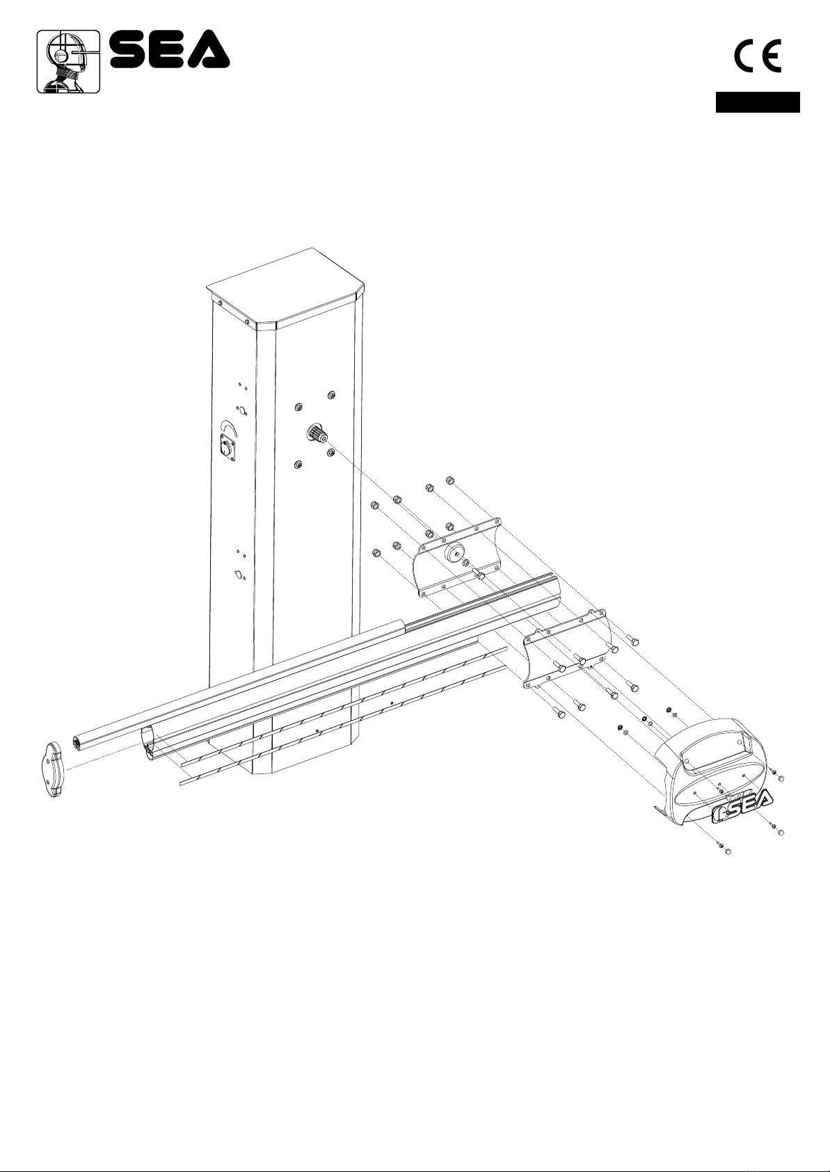
The automation system is composed of the following elements:
1 Adjustable mechanical stop
2 Manual release with key
3 Galvanised steel rocker arm.
4 VERG 24V, casing cover with lock and DIN key
5 Balancing spring.
6 Electronic control unit.
7 Foundation plate out of galvanized steel
8 Emergency batteries 2x12V 2Ah.
9 24V - 2400 rpm electric motor
10 Reduction gear
11 Cataphoresis-treated and polyester painted VERG 24V casing, for outside, protects
all included mechanical and electronic devices from fire, flood, lightning, etc.
Predisposed for the application of photocells, key switch, proximity reader. Stainless
steel casing available on request.
12 Battery charger circuit
Main components:
1) Adjustable mechanical stop
2) Manual release system
3) Rocker arm
4) VERG 24V casing cover
5) Balancing spring
6) Electronic control unit
7) VERG anchoring plate (optional)
8) Emergency batteries 2x12V 2Ah (optional)
9) 24V electric motor
10) Gearbox
11) VERG casing
12) Battery charger circuit (optional with battery kit)
11
6
1
3
4
5
7
8
9
10
11
2
12
Cod. 67411465 Rev.00 - 12/2012

TECHNICAL FEATURES
Supply voltage
Motor power supply
Motor power
Motor speed
Working temperature
Opening/closing time
Protection class
Manual release system
Usage frequency
Anti-crushing device
Holding block
Slowdown
Barrier body treatment
Weight
Electronic equipment
INSTALLATION INSTRUCTIONS
1) Spring position
Thanks to its high flexibility, the barrier you are installing can be closed
on the right-hand or left-hand side of the post, according to your needs.
e.g. if the spring is on the right-hand side, the guard closes on the left
(see Fig. 2).
English
Sistemi Elettronici
di Apertura Porte e Cancelli
International registered trademark n. 804888
®
Fig.2
Fig.1
Opening on the right Opening on the left
12
230 V~ ± 5% - 50/60 Hz 115 V~ ± 5% - 50/60 Hz
24Vdc
60 W
2400
-20° + 55°C
IP55
Yes
60%
A
Yes
E
39 kg
USER 1 24V
RPM
Adjustable
mmeter
lectronic
Cataphoresis treated and polyester painted
128
56
1148
288
203
VERG 230V VERG 115V
Note: The frequency of
use is valid only for the
first hour at 20°C room
temperature.
OVERALL DIMENSIONS:
*To guarantee longer life of the barrier, SEA
recommend to adjust the speed giving an extra time
of at least 1 sec from the Max Speed as for this chart.
** SEA grant those performances only for the 1st
hour of operation. After 1 st hours cycles can drop
up to 50%. Cycles are granted only with slowdown
active. Periodically check the balance of the beam.
VERG 2mt 3mt 4mt 5mt
Max Speed* 2-3 sec 3-4 sec 4-5 sec 5-6 sec
Cycles** 60% 50% 45% 35%
BEAMS RECOMMENDED SPEED
Cod. 67411465 Rev.00 - 12/2012

Concrete
Foundation plate
to be levelled
60°~ clamp opening
Conduit
2) Foundation plate anchoring
−Make a 500 x 500 x 300 mm (depth) hole in
the ground.
−Widen the foundation plate clamps till they
reach approx. 60° (Fig. 3).
−Fill the hole with R425 concrete and place the
foundation plate as shown in Fig. 3.
−Accurately level the plate.
* The middle hole of the plate must be used for
cable routing. Therefore, make sure that the
conduit connected to the hole complies with
current regulations, before filling the hole with
concrete.
Anchoring
nuts and
washers
Hole for the conduit containing
the electrical cables
3) Post anchoring on the foundation plate
−Place the casing so that the holes on the base match the
screws located on the foundation plate.
−Make sure that the conduit for the cables goes through
the large hole of the casing base.
−Insert the bracket for anchoring the spring: A in case of
left-hand mounting, B in case of right-hand mounting; the
bracket must always be positioned towards the inside as
in Fig.4
−Fix the casing on the foundation plate, screwing the
supplied nuts and washers carefully.
English
Sistemi Elettronici
di Apertura Porte e Cancelli
International registered trademark n. 804888
®
Fig.4
Fig.3
500
300
B
A
13
Cod. 67411465 Rev.00 - 12/2012

4) Fixation of the balance
−Carefully insert the roll bearing (A) into the hole 1 or 2 of
the balance in case of left-hand mounting; into hole 3 or 4
in case of right-hand mounting using hinge P and a nylon
hammer.
Attention: The choice of the hole varies according to the beam
length. (SEE BOARD)
−Lubricate with grease the bearing and the washers
.
−Mount the resting devices as shown in Fig. 5
during assembling
5) Mounting of the spring
−Anchor the spring on the bracket which has been mounted
before (S)
−Insert the rod of the spring into the bracket (B) and insert the
nuts (D) without tightening them.
OVAL BEAM
Length
(m)
3
4
5
Balance
position
1 / 4
1 / 4
1 / 4
Spring
(Ø mm)
6
7,5
8,5
Note: Strictly follow the opening time to avoid bad
working
Note: The springs and the bracket of anchorage are supplied with the
beam.
Opening
time
3
4
5
” ÷ 4”
” ÷ 5”
” ÷ 6”
English
Sistemi Elettronici
di Apertura Porte e Cancelli
International registered trademark n. 804888
®
Fig.6
A
P
Fig.5
P
A
1
2
3
4
B
D
S
Keep well
lubricated
with grease
14 Cod. 67411465 Rev.00 - 12/2012
6) Mounting of the oval beam
Note: For 4 and 5 m beams it is recommended to use the fork support or the flexible support.
English
Sistemi Elettronici
di Apertura Porte e Cancelli
International registered trademark n. 804888
®
Fig.7
15
Cod. 67411465 Rev.00 - 12/2012
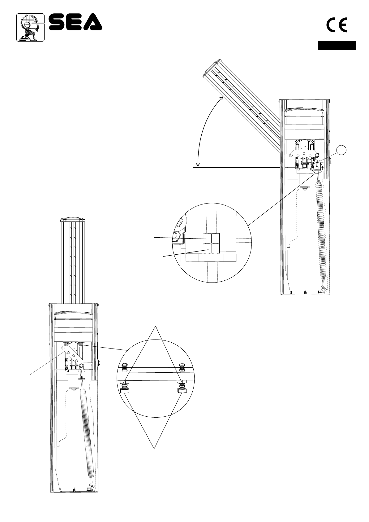
7) Beam balancing
−Release the beam with manual release, so
that it is free to be opened and closed
manually (Fig.8).
−Place the beam at approx. 45°.
−Loosen or tighten the spring stretching nut
until the spring counterbalances the weight of
the 45° beam (Fig. 8). The best balancing
position is obtained when the beam reaches
the position shown in Fig. 8.
−After having obtained the balancing, lock the
nuts of the spring stretcher with the counter
nut and re-block the motor.
Should the balancing of the beam not be
perfect and the length of the spring stretcher
(T) be too long, cut it about half of its length.
Spring
nutstretching
Anchoring
lock nut
8) Beam levelling
Note: this operation must be carried out only if
the beam is not perfectly horizontal (closing
stage) or vertical (opening stage) at the end of its
stroke.
−Release the beam with the special manual
release so that it is free to open and close
manually.
−Release the screws of the limit switch on
unscrewing the nuts on the mechanical stops
(fig.9).
−Loosen or tighten the stop screws so that the
beam is released in its vertical position
(opening stage) (Fig. 9) and horizontal position
(closing stage).
−After having executed the levelling lock the
screws of the limit switch tightening the nuts on
the mechanical stops and re-lock the beam.
Stop adjustment
screws
Lock nuts
Rocker
arm
English
Sistemi Elettronici
di Apertura Porte e Cancelli
International registered trademark n. 804888
®
4°
5
T
Fig. 8
Fig.9
16 Cod. 67411465 Rev.00 - 12/2012

Battery charger
circuit
Note: For a longer duration of the battery it
is recommended to set the charging
current according to the following table:
Battery current (mA) Battery (Ah)
9) Battery charger circuit
English
Sistemi Elettronici
di Apertura Porte e Cancelli
International registered trademark n. 804888
®
GNDGND
GNDGND PSOLPSOL BATBAT 28V28V
++
SS
--
USER24
+ +
- -
= charge 200mA
Solar Panel
Batteries
GNDGND
+
Grey connector
CN1
= charge 360mA
= charge 800mA
~
~
~
12V12V 12V12V
12 or 16
7
2
800
360
200
Fig.10
17
Cod. 67411465 Rev.00 - 12/2012

10) Electrical system
Fig. 11 sketches the electrical system that the barrier requires.
The two numbers located near the electrical cables indicate the cable number and section.
Captions:
1- VERG electronic control unit
2- Transmitting photocell
3- Receiving photocell
4- Key switch
5- Radio receiver
6- Flashing light
7- Push-button station
8- Differential switch
English
Sistemi Elettronici
di Apertura Porte e Cancelli
International registered trademark n. 804888
®
ACCESSORIES FOR VERG
FORK SUPPORT
BATTERY KIT
PHOTOCELLS
KEY SWITCH
WARNING LAMP
Fig.11
11
22
33
44
55
66
77
88
2x1
2x1
4x1
3x1,5
3x1
Fig.11
2X1 1xRG58
18 Cod. 67411465 Rev.00 - 12/2012
RELEASE LOCK
(Optional)
LED
LIGHTS KIT

NOTES
The electrical installation and the operation logics must comply with current regulations. Keep the power cables (motors, power supply)
separated from the control cables (push-buttons, photo-eyes, radio, etc.). Separate conduits should be used to prevent noise issues.
Note: Use “cable clips” and/or “duct/box pipes” fitting close to the control panel box so to protect the interconnection cables against pulling
efforts.
INTENDED USE
VERG system has been designed exclusively for the automation of barriers.
SPARE PARTS
The spare parts orders must be sent to:
SEA S.p.A. Zona Ind.le, 64020 S.ATTO Teramo Italy
SAFETY AND RESPECT FOR THE ENVIRONMENT
We recommend not to spoil the environment with product and circuit packing material.
STORAGE
STORAGE TEMPERATURE
Tmin
-30°C
Tmax
+60°C
Humiditymin
5% without condensation
Humiditymax
90% without condensation
The product must be handled using suitable means.
LONG-TERM STOPAND MAINTENANCE
The disassembly and/or stop and /or maintenance of the VERG automation system must be carried out by skilled and expert technicians.
GUARANTEE LIMITS
For the guarantee see the sales conditions on the official SEAprice list.
NOTE: THE MANUFACTURER SHALL NOT SHOULDER ANY RESPONSIBILITIES IN CASE OF DAMAGE CAUSED BY
INAPPROPRIATE, WRONG OR CARELESS USE.
SEA reserves the right to make all the necessary changes and modifications of the products and / or manuals without giving prior
notice.
English
Sistemi Elettronici
di Apertura Porte e Cancelli
International registered trademark n. 804888
®
11) Release system
To release operate as follows
- Turn the protection cap of the release.
- Insert the and turn it about 180° into
clockwise direction until the beam is released (Fig.
12).
- Open manually the beam.
To re-lock operate as follows
- Turn the into anti-clockwise direction
(Fig. 13).
- Extract the key.
- Re-close the protection cap.
T shaped key
T shaped key
PERIODICAL MAINTENANCE
All above mentioned operations must be executed exclusively by authorized installers.
Check the functionality of the release
Lubricate the bearing of the balance
Check the efficiency of the spring
Check the beam fixing screws and the balance and the casing
Check the integrity of the connexion cables
Check the efficiency of the batteries (where included)
Check and eventually adjust the value of intervention of the
anti-crash sensor.
Annually
Annually
Annually
Annually
Annually
Annually
Annually
To the attention of users and technicians
180°
Fig.12 180°
Fig.13
Release Lock
19
R
(OPTIONAL)
elease key with extractable cylinder
Release
Cod. 67411465 Rev.00 - 12/2012
Fig.14
Table of contents
Other SEA Automatic Barrier manuals


Popular Automatic Barrier manuals by other brands


Gerreka
Gerreka ULTRA Quick installation and programming guide

barrier
barrier SWING GATE INSTALLATION PROCEDURE

O&O
O&O NIGHT&DAY 35 Xtreme Instructions for installation, use and maintenance

DoorKing
DoorKing 1620 Series installation manual

nologo
nologo ACTIVE-A Series Manual and directions for the installer

PERCo
PERCo ST-02 Series Assembly and operation manual


X Series user manual")
