MODULIERTE INFRAROTLICHTSCHRANKEN
ANWEISUNG
Das vorliegende Handbuch wendet sich an Personen, die zur Installation von "ELEKTROGERÄTEN" befähigt
sind und setzt eine gute beruiche Kenntnis der Technik voraus. Die Verwendung und die Installation dieser
ApparaturmußgenaudenAngabendesHerstellersunddengeltenden Sicherheitsbestimmungen entsprechen.
Achtung! Nur für EG-Kunden – WEEE-Kennzeichnung.
Das Symbol zeigt an, dass das Produkt am Ende seines Lebenszyklus getrennt von
anderen Abfällen gesammelt werden muss. Der Benutzer muss daher das Gerät in
geeignete Zentren für die getrennte Sammlung von Elektronik- und Elektroschrott brin-
gen oder zum Zeitpunkt des Erwerbs eines neuen Geräts gleicher Art im Verhältnis eins
zu eins beim Händler abgeben. Die geeignete getrennte Sammlung für die Zuführung
zum Recycling, zur Aufbereitung und zur umweltfreundlichen Entsorgung trägt dazu bei, mögliche
negative Auswirkungen auf die Umwelt und die Gesundheit zu vermeiden und fördert das Recycling
der Materialien. Die widerrechtliche Entsorgung des Produkts durch den Besitzer führt zur Anwendung
der von den geltenden Vorschriften im Mitgliedstaat der Europäischen Gemeinschaft vorgesehenen
Verwaltungsstrafen.
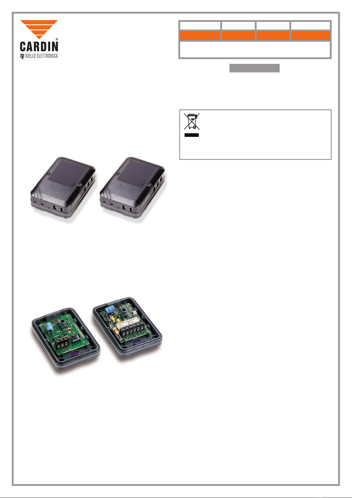
Beschreibung
Die modulierte Infrarotschranke besteht aus einem Sender und einem Empfänger. Die Geräte benden sich
in einem stoßfesten, wasserdichten Plastikbehälter. Das Gehäuse ist für eine Wandbefestigung vorgesehen:
die spezielle Gummiauage ("A" Abb.1) ermöglicht auch eine Anpassung an nicht ebene Oberächen. Das
Diodensystem (Lichtsender-Empfänger), das mit einer Führung für das Lichtbündel ausgestattet ist, bleibt
immer in xer Position. Das Gerät wurde gemäß den Sicherheitsnormen gebaut. Schutzgrad IP54.
Verwendungsmöglichkeiten
Die Infrarotlichtschranke ist ein leistungsfähiges Sicherheits- und Kontrollsystem, zur Beschützung von
Durchgängen oder Zonen innerhalb derer die Montage von automatisierten Türen oder Gittertoren notwendig
ist, sowie zur Überwachung von allgemeinen Einfahrten und Durchgängen, die sich innerhalb oder außerhalb
von Gebäuden benden. Dieses Gerät ist zur Verwendung bei Durchgängen geeignet, deren maximale Länge
10 m beträgt. Die Benützung und Montage dieser Geräte, muss unter strengster Beachtung der Hersteller-
anweisungen und der geltenden Sicherheitsvorschriften erfolgen.
BeieventuellenSchäden aufgrund unsachgemäßer,ungeeigneter oderfalscherBenützung,kannderHersteller
nicht zur Verantwortung gezogen werden.
Ausführungen
CDR861- In einer Packung sind die Teile zur Aufputzausführung erhalten:
- 1 Sender im Gehäuse
- 1 Empfänger im Gehäuse
- Satz Dichtungen
- Satz Schrauben
Technische Eigenschaften
- Infrarotlichtsendungmittels GaAs Dioden (Galliumarsenid), mit doppeltem Lichtsenderund kontinuierlicher
Modulation 610 Hz.
- Wellenlänge der Infrarot-Lichtsendung: 950 mm.
- Stromversorgung 12-24Vac/dc.
- Steuerung: Doppelrelais mit Austausch in Serie.
- Relais, höchste umschaltbare Leistung mit Ohmscher Belastung.
28W in dc/60VA in ac max. Spannung 40Vac/dc
Stromaufnahmen:
12V ac/dc, 30 mA der Empfänger + 40 mA der Sender
24V ac/dc, 36 mA der Empfänger + 53 mA der Sender
- Betriebstemperatur: -10…+55 °C
- Rotes Led zur Anzeige das der Sender unter Spannung ist.
- Rotes Led und Test Point zur exakten Zentrierung beim Empfänger.
- Reichweite unter allen Bedingungen, auch bei dichtem Nebel, Regen oder Staub, 10 m.
Montage: (Abb. 2-5)
A) Sender und Empfänger werden normalerweise stirnseitig, auf derselben geometrischen Achse und in
gleicher Höhe vom Boden aus, befestigt.
- Die Montage kann auf jederKonstruktion erfolgen. ÜberprüfenSie die Ebenheit derFläche und die Linearität
der Konstruktion an der das Gerät angebracht werden soll. Wenn die Bedingungen optimal sind, genügt
eine einfache Kontrolle der Maßübereinstimmung für die Befestigung des Empfängers und des Senders,
bis die unter Punkt Aaufgezählten Bedingungen erfüllt sind. Zur Erzielung einer einwandfreien Installation
sind die folgenden Anweisungen, genauestens zu beachten:
- Legen Sie die Befestigungspunkte, nach den Erfordernissen der Anlage fest.
- Sorgen sie dafür, dass der Kabelverlauf an der Struktur, bis zu den Befestigungspunkten geht.
- Zeichnen Sie die Befestigungslöcher, unter Verwendung der in der Verpackung mitgelieferten Lochscha-
blone, an.
- Nehmen Sie die Schaltung aus der Basis ("D" Abb. 2).
- Befestigen Sie die Basis an der Wand, wobei Sie die Anschlußkabel durch die vorgesehen Löcher führen
("A-B" Abb. 2).
- Geben Sie die Schaltung wieder in die Basis und führen sie den Anschluss durch (Abb. 3).
- Kontrollieren Sie nach der Aktivierung des Systems, dessen Leistungsfähigkeit. Wenn die Konstruktion,
sich jedoch als nicht regelmäßig erweist, ist es günstiger eine elektrische Funktionskontrolle vor der
endgültigen Befestigung des Gerätes durchzuführen.
Nachdem der Sender angeschlossen und befestigt wurde, ist der Empfänger anzuschließen, indem man
in der folgenden Weise vorgeht:
Überprüfung und Ausrichtung (Abb. 4)
Beachte: Wenn sowohl der Sender als auch der Empfänger unter Spannung sind, ist das Led des Senders
dauernd eingeschaltet; das EmpfängerLed ist bei zentrierter Lichtschranke(aktiviertes System) ausgeschaltet
und bei nicht zentrierter Lichtschranke eingeschaltet. Um eine Überprüfung der Zentrierung in der Installati-
onsphase durchführen zu können ist in der folgenden Weise vorzugehen:
1) Führen Sie die Spitzen eines normalen Testgerätes (2 Vdc Vollausschlag) zu den entsprechenden
Testbereichen(TestPoints),wobeidieexaktePolung,laut den Angaben auf dergedrucktenSchaltung
zu beachten sind.
2) Die Ablesung auf dem Tester durchfuhren, wobei eine Abweichung des Signals um 0,4 V als optimal
zu betrachten ist. Falls eine größere Abweichung gemessen werden sollte, wird das Signal durch
Betätigung des entsprechenden Trimmers des Empfängers herabgesetzt, bis das die Abweichung
den optimalen Wert angibt.
Beachte:Kein fester Teil darf sichzwischenEmpfängerundSender benden. Sollte eine Stoßsicherungnotwen-
dig sein, die das Lichtbündel unterbricht, ist es empfehlenswert sich mit einem unserer Techniker zu beraten.
BARRERA DE RAYO INFRARROJO MODULADO
ADVERTENCIAS
Este manual se dirige a personas habilitadas para la instalación de “aparatos utilizadores de energía
eléctrica” y exige el buen conocimiento de la técnica, realizada profesionalmente. El uso y la instalación
de este equipo debe cumplir estrictamente con las indicaciones facilitadas por el fabricante y las normas
de seguridad vigentes.
¡Atención! Solo para clientes de la Unión Europea - Marcación WEEE.
El símbolo indica que el producto, una vez terminada su vida útil, debe ser recogido por
separado de los demás residuos. Por lo tanto, el usuario deberá entregar el equipo en los
centros de recogida selectiva especializados en residuos electrónicos y eléctricos, o bien
volverlo a entregar al revendedor al momento de comprar un equipo nuevo equivalente,
en razón de uno comprado y uno retirado. La recogida selectiva destinada al reciclado,
al tratamiento y a la gestión medioambiental compatible contribuye a evitar los posibles efectos
negativos en el medio ambiente y en la salud, y favorece el reciclado de los materiales. La gestión
abusiva del producto por parte del posesor implica la aplicación de las sanciones administrativas
previstas por la normativa vigente en el Estado comunitario al que pertenece.
Descripción
Barrera de rayo infrarrojo modulado compuesta por un proyector y un receptor. Los equipos están
colocados en una caja de plástico estanca y a prueba de choque. La caja ha sido concebida para ser
jada en la pared: su base de apoyo de goma ("A" g. 1) ofrece una buena adherencia también en caso
de supercies irregulares. El sistema de diodos (emisor-receptor) provisto de guía del haz luminoso
permanece en una posición ja. Equipo provisto de mando con doble relè con cambios en serie Aparato
fabricado cumpliendo con las normas de seguridad.
Grado de protección IP55.
Posibilidades de uso
La barrera de rayo infrarrojo representa un sistema de seguridad y de control ecaz para la producción de
pasos o espacios donde se instalan puertas y verjas automatizadas, así como para la dotación y el control
de pasajes para vehículos o peatones colocados por fuera o en el interior de los edicios.
Adecuada para pasos cuya abertura máxima no es superior a 10 m.
El uso y la aplicación de estos equipos tienen que respetar rigurosamente las indicaciones dadas por el
fabricante así como las normas de seguridad en vigor. El fabricante rehusa cualquier responsabilidad en
caso de daños causados por usos inapropriados, equivocados o irrazonables.
Versiones
CDR861- La confección comprende los elementos para la aplicación en supercie
- 1 proyector en una caja
- 1 receptor en una caja
- Serie de juntas
- Serie de tornillos
Características técnicas
- Emisión infrarroja con diodo GaAs (Arseniuro de Galio) con doble emisor, con modulación continua
610 Hz.
- Longitud de onda de la emisión infrarroja: 950 mm.
- Alimentación 12-24Vac/dc.
- Mando: doble relè con cambios en serie.
- Control: doble relais con intercambios en serie, según lo que dispone la normativa (relativa al dispositivo
de protección contra los accidentes, para puertas motorizadas).
- Relais máx. potencia conmutable con carga resistiva
28W en dc/60VA en ac - Tensión máx. 40Vac/dc
- Absorción:
12V ac/dc, 30 mA el receptor + 40 mA el proyector
24V ac/dc, 36 mA el receptor + 53 mA el proyector
- Temperatura de funcionamiento: -10… +55°C
- Led rojo para señalar que hay corriente en el proyector.
- Led rojo y test point para el centraje preciso en el receptor.
- Alcance 10 m con cualquier tipo de tiempo, también en caso de niebla espesa, lluvia o polvo.
Instalación (g.2-5)
A)El proyector y el receptor normalmente se jan sobre el mismo eje geomètrico, uno frente al otro y a la
misma altura.
- La instalación es posible sobre todos los tipos de estructura.
Comprobar que las supercies de instalación sean planas y que la estructura sea lineal.
Si las condiciones son óptimas, se necesita sólo controlar la correspondencia entre las medidas de
jación del receptor y las del proyector hasta alcanzar la condición A.
Para realizar la instalación correctamente, seguir con atención las indicaciones siguientes:
- Elegir los puntos de jación según la necesidad de la instalación.
- Prever el recorrido de los cables sobre la estructura hasta los puntos de jación.
- Señalar los agujeros de jación por medio de la plantilla de taladrar.
- Quitar el circuito de la base ("D" g. 2).
- Fijar la base en la pared, haciendo pasar los cables de conexión por el agujero previsto ("A-B" g. 2).
- Meter nuevamente el circuito en la base y realizar las conexiones (g. 3).
- Después de haber acabado la instalación, comprobar su eciencia. En caso de estructura irregular,
más vale controlar el funcionamiento eléctrico antes de jar denitivamente los aparatos.
Entonces, después de haber conectado y jado el proyector, conectar el receptor y seguir las indica-
ciones siguientes:
Verificación y puesta a punto (g. 4)
N.B. - Cuando se alimenta el proyector y el receptor, el LED del proyector se enciende permanentemen-
te; el LED del receptor permanece apagado cuando la fotocélula está centrada (sistema activado) y se
enciende cuando la fotocélula no está centrada. Para vericar el centraje durante las fase de instalación,
seguir las indicaciones siguientes:
1) Introducir las puntas de un probador (2 Vdc máximo escala) en las zonas de prueba (test point)
y eso respetando la polaridad exacta indicada en el circuito impreso.
2) Realizar una lectura con el tester, considerando óptima una desviación de la señal igual a 0.4 V.
en el caso que se obtenga una desviación superior se espera la señal actuando sobre el trimmer
correspondiente del recibidor hasta restablecerla a su valor óptimo
N.B. - Ningún elemento jo puede interponerse entre el receptor y el proyector.
Si se necesitan protecciones a prueba de choque que intereren con el haz, se aconseja consultar con
uno de nuestros técnico.
DEUTSCH ESPAÑOL