SEA VELA User manual

INSTALLATION MANUAL
Thank you for choosing a SEAs.r.l. product. This choice will give you
the opportunity to understand that our company aims at combining
high-tech and remarkable reliability and safety, thanks to studies,
research and the accurate analysis of our customers' needs, without
underminingthesimpleuseandinstallationofourproducts.
Generalfeatures
VELAis an electro-mechanical barrier (2, 3, 4, 5 m) recommended for
the automation of access points which require a high opening/closing
speed (parking lots, motorways, airports, etc.) and frequent use
features.
The automation comes with an anti-squeezing safety system
through by pass valves for the regulation of the force which doesn't
exceed15kgonthebeam,protectingpeopleandthingsfrompossible
accidents.Asystemofhydraulicdeceleration(onrequest)guarantees
the total control of the present inertial force in case of lack of power
supply and a release system allows the manual opening in case of
emergency.
Theautomationsystemiscomposedofthefollowingelements:
1 Adjustablemechanicalstop
2 ManualreleasewithDINkey
3 Galvanisedsteelrockerarm
4 VELA,casingcoverwithlockandDINkey
5 Balancingspring
6 ElectroniccontrolunitGATE1(code23001120/1),acomplexdevicewhichcanbeusedtoprogramandmanageall
theoperationandsafetysystems
7 Fixationplateoutofgalvanizedsteel
8 Hydrauliqueunit
9 Rollerbearing
10 Cataphoresis-treated and polyester painted VELA casing, for outside, protects all included mechanical and
electronicdevicesfromfire,flood,lightning,etc.
Predisposed for the application of photocells GHOST 40, key switch Key Plus, proximity reader Reader Prox.
Stainlesssteelcasingavailableonrequest.
English
Sistemi Elettronici
di Apertura Porte e Cancelli
International registered trademark n. 804888
®
1010
88
66
55
44
33
22
11
77
99
Cod. 67410035 Rev 06 - 06/2010 15

Supply voltage
Force absorption
Opening/closing time
Thermoprotection
Oil quantity
Max. Beam length
Protection degree
Start condensator
Absorbed power
Working temperature
Manual release system
Usage frequency
Holding block
Slowdown
Barrier body treatment
Weight
Electronic equipment
: 230 V~ ± 5% - 50/60 Hz
: 220W
: 3,5 - 7,5 s
: 130°
: 1,8 L
: 5 m
: Ip55
: 12,5 uF
: 1,1 A
: -20°C/55°C
: yes
: 75%
: yes
: hydraulic (on request)
: Cataphoresis treated
and polyester painted
: 42 kg
: GATE 1 (cod. 23001120/1)
Technical features
Overall dimensions:
85 (B am rotation axis0 e )
Round beam
profile
Rectangular beam
profile
English
INSTALLATION INSTRUCTIONS
1)Springposition
Thanks to its high flexibility, the barrier you are installing can be closed on the
right-handorleft-handsideofthepost,accordingtoyourneeds.
e.g.ifthespringisontheright-handside,theguardclosesontheleft(seeFig.2).
Left-hand mounting Right-hand mounting
Sistemi Elettronici
di Apertura Porte e Cancelli
International registered trademark n. 804888
®
Oval beam
profile
Fig.1 Fig.2
Cod. 67410035 Rev 06 - 06/2010
16
70
25
107
76
30 30
50
1015
300 200
128
56
780
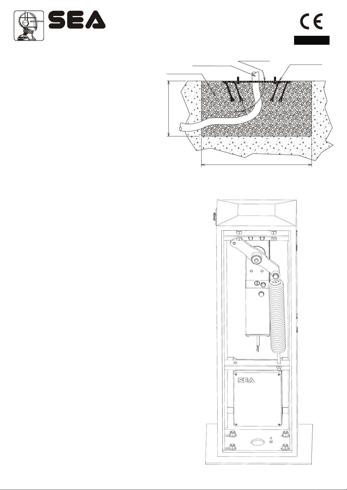
3) Postanchoringonthefoundationplate
-Place the casing so that the holes on the base match the
screwslocatedonthefoundationplate.
-Makesurethattheconduitforthecablesgoesthroughthelarge
holeofthecasingbase.
-Fix the casing to the foundation plate screwing with care the
delivereddiceand washers
Fig.4
English
Fig.3
Concrete
Foundation plate
to be levelled
60°~ cla p open ngm i
Conduit
500
03 0
2) Foundationplateanchoring
-Make a 500 x 500 x 300 mm (depth) hole in the
ground.
-Widen the foundation plate clamps till they reach
approx.60°(Fig.3).
-Fill the hole with R425 concrete and place the
foundationplateasshowninFig.3.
-Accuratelyleveltheplate.
*The middle hole of the plate must be used for cable
routing. Therefore, make sure that the conduit
connected to the hole complies with current
regulations,beforefillingtheholewithconcrete.
Sistemi Elettronici
di Apertura Porte e Cancelli
International registered trademark n. 804888
®
Cod. 67410035 Rev 06 - 06/2010 17

5)Mountingofthespring
-Insert the connecting rod of the spring into the hole (A or B) and
insertthedice(D)withoutlocking them(Fig.6). Fig.6
Note:Thespringsandthebracketof anchoragearesuppliedwiththebeam
Fig.5
AB
D
Round beam
Barrier Length D. Spring Cod. kit beam
2 5 mm 11910045
2.5 5,5 mm 11910050
3 6 mm 11910055
4 6,5 mm 11910060
5 7 mm 11910065
Rectangular beam
Barrier Length D. Spring Cod. kit beam
2 5,5 mm 12710180
3 6 mm 12710185
4 7 mm 12710190
5 8 mm 12710195
Rectangular beam + skirt
Barrier Length D. Spring Cod. kit beam
3 6,5 mm 12710091
3,5 7 mm 12710092
4 8 mm 12710093
Articulated beam dx sx
Barrier Length D. Spring Cod. kit beam
3 7 mm 11902010
3 7 mm 11902020
3,5 8 mm 11902005
3,5 8 mm 11902015
Opening times
Pump Opening time
1 7,5 s
1,5 5,0 s
2 3,5 s
2 speed 2,5 s
4) Fixingofthespringontherockerarm
-Insertwithcaretherollerbearing(C)inthebuckle(B)andexecutethe assemblageasFig.5.
-Lubricate withgreasethebearingandthewashers.
-MounttherestingdevicesasshowninFig.5
-Attheendofinstallationtakeoffthe breatherscrews.
A
B
C
D
EBreather screw
Before putting in function
replace the fill in cap with
the breather cap
English
Sistemi Elettronici
di Apertura Porte e Cancelli
International registered trademark n. 804888
®
Oval beam
Barrier Length D. Spring Cod. kit beam
2 5,5 16400005
2,5 6 16400008
3 6 16400008
4 7 16400015
5 8 16400026
Oval beam + skirt
Barrier Length D. Spring Cod. kit beam
2 5,5 16400005
2,5 6 16400008
3 6,5 16400010
4 8 16400026
Cod. 67410035 Rev 06 - 06/2010
18

Fig.7
Fig.8
Screw and dice for
locking the rod/beam
English
6) Beaminstallation
Rectangularbeaminstallation(from2to5meters)
-Insertthebeaminverticalpositionandfixitwiththespecialscrewandthewasher.
-Insert the beam on the bracket with the rubber turned to the closing side and fix it with the special screws, washers and nuts
(Fig.8)
Mountingoftheroundbeam(from2to5meters)
-Insertthebracketofbeamanchorageinverticalpositionandfixitwiththespecialscrewandwasher.
-Insertthebeamonthebracketandfixitwiththespecialscrews,thewashersandthenuts(Fig.7).
Attention:Beforeinsertingthebracketofanchorage,insertthescrewsofanchorageintothesame.
Tightening screw
and washer
Beam anchoring
bracket Round
beam
Grooved
shaft
beam anchoring
bracket
Tightening
screw
and washer
Grooved
shaft
Rectangular
beam
Sistemi Elettronici
di Apertura Porte e Cancelli
International registered trademark n. 804888
®
Cod. 67410035 Rev 06 - 06/2010 19

Mountingoftheovalbeam
Note:For4and5mbeamsitisrecommendedtousetheforksupportortheflexiblesupport.
Sistemi Elettronici
di Apertura Porte e Cancelli
International registered trademark n. 804888
®
English
Fig.9
Cod. 67410035 Rev 06 - 06/2010
20

7) Mounting of the skirt on the beam
Fig.10
Fig.11
English
Sistemi Elettronici
di Apertura Porte e Cancelli
International registered trademark n. 804888
®
Cod. 67410035 Rev 06 - 06/2010 21

Sistemi Elettronici
di Apertura Porte e Cancelli
International registered trademark n. 804888
®
Fig.12
Fig.13
English
Mounting of the skirt on the oval beam
Cod. 67410035 Rev 06 - 06/2010
22

Fig. 14
Fig. 15
54 54
9)Forceadjustment
If necessary the force of thrust of the beam can be
adjustedthroughthetwocalibrationscrews (grey and
yellow) placed on the side of the hydraulic unit
(Fig.16).
*The automation is adjusted at 15 kg force ex works
sotoguaranteetheanti-crushsafety.Werecommend
toadjustitonlyincaseofnecessity.
Fig.16
- +
English
8) Beambalancing
-Release the beam with manual release, so that it is
free to be opened and closed manually (Fig.18).
-Place the beam at approx. 45°.
-Loosen or tighten the spring stretching nut until the
spring counterbalances the weight of the 45° beam
(Fig. 14). The best balancing position is obtained when
the beam reaches the position shown in Fig. 14.
-After having obtained the balancing, lock the nuts of
the spring stretcher with the counter nut and re-block
the motor.
Spring
nutstretching
Anchoring
lock nut
10) Beamlevelling
Note: this operation must be carried out only if the beam is not
perfectly horizontal (closing stage) or vertical (opening stage) at
the end of its stroke.
-Release the beam with the special manual release so that it is
freetoopenandclosemanually.
-Release the screws of the limit switch on unscrewing the nuts
onthemechanicalstops(fig.15).
-Loosenor tightenthestopscrewssothatthebeam isreleased
in its vertical position (opening stage) and horizontal position
(closingstage)(Fig.15).
-After having executed the levelling lock the screws of the limit
switchtightening the nutson the mechanicalstops and re-lock
thebeam.
Sistemi Elettronici
di Apertura Porte e Cancelli
International registered trademark n. 804888
®
Cod. 67410035 Rev 06 - 06/2010 23
English
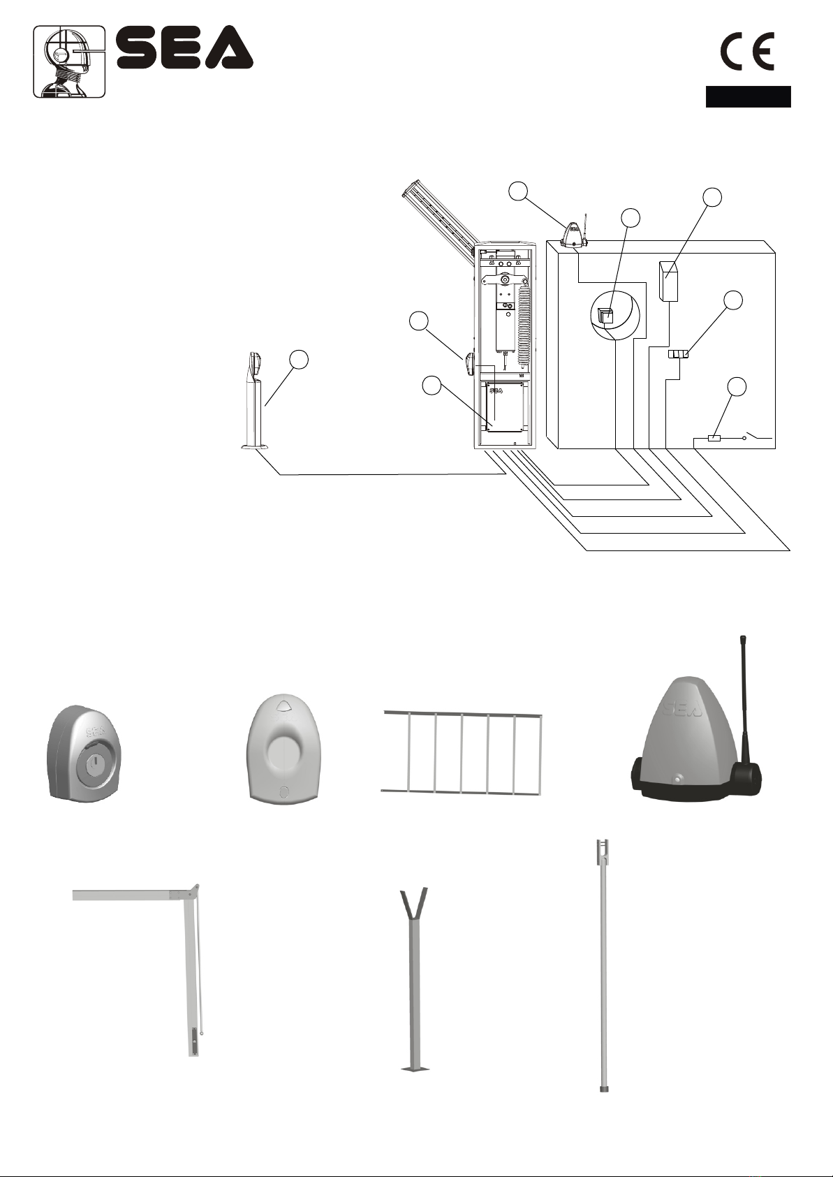
11) Electricalsystem
Fig. 17 sketches the electrical system that the barrier requires.
The two numbers located near the electrical cables indicate the cable number and section.
Captions:
1- GATE 1 electronic control unit
2- Transmitting photocell (Ghost 40)
3- Receiving photocell (Ghost 40)
4- Key switch (Key Plus)
5- Radio receiver
6- Flashing light (Flash)
7- Push-button station
8- Differential switch
Sistemi Elettronici
di Apertura Porte e Cancelli
International registered trademark n. 804888
®
11
22
44
55
66
77
88
2x1 2x1 2x1
4x1 3x1,5
3x1
Fig.17
33
3x1
GHOST 40 - GHOST 50
ACCESSORIES FOR VELA
* FORK SUPPORT * FEXLIBLE SUPPORT
(ONLY BEAM)
* it is reccommended to mount with beams which are longer than 3 m.
SKIRT
ARTICULATED BEAM
KEY SWITCH
WARNING LAMP
Cod. 67410035 Rev 06 - 06/2010
24

NOTES
The electrical installation and the operation logics must comply with current regulations. Keep the power cables (motors, power
supply) separated from the control cables (push-buttons, photo-eyes, radio, etc.). Separate conduits should be used to prevent
noiseissues.
Note: Use “cable clips” and/or “duct/box pipes” fitting close to the control panel box so to protect the interconnection cables
againstpullingefforts.
Note: The beam is not equipped with movement inversion system in case of obstacles.To respect the laws EN 12453 and EN
12445itisrecommendedtoinsertexternaldisposalsintoit.
INTENDED USE
VELAsystemhasbeendesignedexclusivelyfortheautomationofbarriers.
SPARE PARTS
The spare parts orders must be sent to:
SEA s.r.l. Zona Ind.le, 64020 S.ATTO Teramo Italy
SAFETY AND RESPECT FOR THE ENVIRONMENT
Werecommendnottospoiltheenvironmentwithproductandcircuitpackingmaterial.
CONFORMITY REQUIREMENTS
VELA automation system complies with the following standards:
(Machine Directive)
(ElectromagneticCompatibilityDirective)
(LowVoltageDirective)
2006/42/CE
2004/108/CE
2006/95/CE
English
Sistemi Elettronici
di Apertura Porte e Cancelli
International registered trademark n. 804888
®
To the attention of users and technicians
12)Releasesystem
Toreleaseoperateasfollwos
- Turntheprotectioncapofthelock.
- Insert the key into the same and turn it about 180° into anti-clockwise
directionuntilthebeamisreleased(Fig.18).
- Openmanuallythebeam.
Tore-lockoperateasfollows
- Turnthekeyintoclockwisedirectionuntilit’sblocked.(Fig.19).
- Extractthekeyinverticalposition.
- Re-closetheprotectioncap. Fig.18 Fig.19
180°
PERIODICALMAINTENANCE
Check the functionality of the release
Lubricate the bearing of the balance
Check the efficiency of the spring
Check the beam fixing screws and the balance and the casing
Check the integrity of the connexion cables
Check and eventually adjust the efficiency of the By pass valves
Annually
Annually
Annually
Annually
Annually
Annually
Allabovementionedoperationsmustbeexecutedexclusivelybyauthorizedinstallers.
INITIALCHECKANDPUTTINGINSERVICE
Afterhavingcompletedallnecessaryoperations,forthecorrectinstallationoftheproductVELA,describedinthepresentmanual
and after having valued all resting risks which could arise in whatever installation is necessary to test the automation to
guarantee the max. security and in particular way to guarantee the respect of what foreseen by the law and the normatives in
force.Inparticularthetestmustbeexecuted followingthe EN12445 ruelwhichestablishesthetestingmethodsforthetesting of
thegateoperatorsrespectingtheestablishedlimitsbytheEN12453law.
Cod. 67410035 Rev 06 - 06/2010 25

LONG-TERMSTOPANDMAINTENANCE
The disassembly and/or stop and /or maintenance of the VELA automation system must be carried out by skilled and expert
technicians.
GUARANTEE LIMITS
VELA system is guaranteed for 24 months, starting from the date stamped on the product. The product is covered by the
guaranteeprovidedthatthedamagedwasnotcausedbyinappropriateuse,changesortampering.
The warranty shall be valid only for the original buyer.
NOTE: THE MANUFACTURER SHALL NOT SHOULDER ANY RESPONSIBILITIES IN CASE OF DAMAGE CAUSED BY
INAPPROPRIATE,WRONGORCARELESSUSE.
SEAreservestherighttomakeallthenecessarychangesandmodificationsoftheproductsand/ormanualswithoutgivingprior
notice
STORAGE
STORAGE TEMPERATURE
Tmin
-30°C
Tmax
+60°C
Humiditymin
5% without condensation
Humiditymax
90% without condensation
When being transported this product must be properly packaged and handled with care.
English
Sistemi Elettronici
di Apertura Porte e Cancelli
International registered trademark n. 804888
®
To the attention of users and technicians
ARRANGEMENTS
Read attentively the installation manual as it gives important indications concerning safety, installation, use and
maintenance.
Installation, maintenance, reparation, controls and eventual putting out of function of the product must be executed
byqualifiedstaffonly.
For the security of people it is important to follow with attention all the advises and instructions in this
manual.Awronginstallationorawronguseoftheproductcancauseseverdamagestopeople.
2
The max. length of the power supply cable between control unit and motors is 10m, use cables with 2,5 mm
section.
Use wirings with double insulated cables (cables with sheath) up to the immediate proximities of the terminals
especiallyforthepowersupply cable(230V ).
Thecontrolunitmustnotbeusedbypeople(includingchildren)whosephysical,sensoryormentalabilityisreduced,
or with lack of experience or knowledge, unless they are guarded or have been instructed on how to use the control
unit by a person respondsible for their safety. Children must be guarded to make sure that they don't play with the
controlunit.
Foreseeonthepowersupplynetoftheautomationadevicethatassuresthecompleteomnipolardisconnectionfrom
thenet,withadistanceofopeningofthecontactsoneachpoleofatleast3mm.Thosedevicesofdisconnectionhave
tobe foreseen on the power supplynetaccordinglytotherulesof installation, andtheyhavetobedirectlyconnected
tothepowersupplyterminals.
It is necessary to keep in adequate distance (at least 2.5 mm in the air) the low tension conductors (230V ) from the
very low tension conductors (SELV) or to use a suitable sheath of at least 1 mm which supplies an additional
insulation.
Make sure that during installation the power supply and interconnection cables cannot come into contact with
pointedorsharpextremities.
~
~
Cod. 67410035 Rev 06 - 06/2010
26

Dispose of the package materials (plastics, carton, polistirene, etc.) respecting the laws in order. Keep nylon and
polistirenebagsoutofthereachofchildren.
Savetheseinstructionsforfurtherinformationattachingthemtothetechnicaldocuments.
Thisproducthasbeenprojectedandbuiltexclusivelyfortheusedescribedinthisinstrucitonmanual.
Usesnotindicatedinthismanualcoulddamagetheproductandbesourceofdanger.
SEAdeclinesallresponsibilityforimproperordifferentusefromtheoneforwhichithasbeenplanedanddescribedin
thepresentmanual.
Don'tinstalltheproductinexplosiveatmospheres.
SEAdeclines all responsibility for the non-observance of the good technique in the construction of closings (doors,
gates,etc.),aswellasfor thedeformationswhichcouldoccureduringtheuse.
Remove the power supply before any intervention on the installation. Disconnect also possible battery buffers if
present.
Make sure that the earth installation has been correctly made: connect all the metallic parts of the closing (doors,
gates,etc.)andallthecomponentsoftheinstallationprovidedwithearthterminals.
Applyall the safetydevices (photocells, sensitiveedges, etc.) whichare necessary toprotect the areafrom dangers
ofcrushing,conveying,cutting.
SEAdeclines all responsibility for safety and for the correct functioning of the automation if parts of other producers
areused.
Useonlyoriginalpartsforanymaintenanceorreparation.
Donotmodify thepartsoftheautomationifnotexplicitly authorizedbySEA.
Instruct the user of the installation on the applied command systems and how to manually open the gate in case of
emergency.
Whatisnotexplicitlycontainedintheseinstructionsisnotpermitted.
English
Sistemi Elettronici
di Apertura Porte e Cancelli
International registered trademark n. 804888
®
To the attention of users and technicians
Cod. 67410035 Rev 06 - 06/2010 27
Table of contents
Other SEA Automatic Barrier manuals


Popular Automatic Barrier manuals by other brands

Nice
Nice S4BAR Instructions and warnings for installation and use

Roger Technology
Roger Technology Agilik Series Instruction and warnings for the installer

RITE-HITE
RITE-HITE GUARDRITE STRAP Installation and owner's manual

CAME
CAME G2080EZC Installation and operation manual

Chamberlain
Chamberlain LiftMaster Professional 475M manual

FAAC
FAAC 617 manual


