SEA ISUZU FSR User manual
OWNER’S MANUAL (SEA ISUZU FSR/FSD EV)
SEA Electric Pty Ltd. 13 Advantage Drive Dandenong South, Victoria, Australia 3175.
T/ +613 9706 8489. ABN 42 618 821 346.

OWNER’S MANUAL (SEA ISUZU FSR/FSD EV)
SEA-OWS-QA-004/5 ISSUE DATE: 30/05/2020 Page 2of 56
Contents
1. Introduction ........................................................................................................................................3
2. Safety Notices and Safety Instructions ...............................................................................................4
3. Vehicle Layout –Components and Specifications ..............................................................................6
SEA-Drive® layout and components ...................................................................................................7
HV Li-Ion Battery Pods ........................................................................................................................8
4. Controls and Display .........................................................................................................................12
Drive Selector....................................................................................................................................12
Display...............................................................................................................................................13
5- Charging the Traction Batteries........................................................................................................16
Vehicle Charger Connection Socket..................................................................................................18
Disconnecting the Charge Cable .......................................................................................................21
Kwik Portable Charger ......................................................................................................................22
6- Pre-Start Checks................................................................................................................................26
7- Driving the Vehicle............................................................................................................................27
Starting the SEA-Drive® Vehicle........................................................................................................27
Driving the SEA-Drive® Vehicle .........................................................................................................28
Regenerative Braking........................................................................................................................29
8- Parking the Vehicle ...........................................................................................................................30
9- Maintenance.....................................................................................................................................31
Maintenance-free 24V Battery .........................................................................................................33
Fuse Box (FB01).................................................................................................................................35
Relay Box (FB02) ...............................................................................................................................36
10- Inspection and Service Scheduling .................................................................................................37
11- Trouble Shooting Guide..................................................................................................................39
12- Towing Procedure...........................................................................................................................41
Appendix A: Charging Procedure..........................................................................................................42
Charging Procedure (Two-LED Function)..........................................................................................46
Charging Procedure (Alternate Mounting).......................................................................................50
Appendix B: Wall Charger Specs...........................................................................................................54
Appendix C: Emergency Quick Response..............................................................................................55

OWNER’S MANUAL (SEA ISUZU FSR/FSD EV)
SEA-OWS-QA-004/5 ISSUE DATE: 30/05/2020 Page 3of 56
1. Introduction
To ensure you are fully aware of safety and operational information, the following symbols are used
throughout this manual;
All information contained in this manual is based on the latest product information available at the
time of printing. We reserve the right to make changes at any time without notice. No part of this
publication may be reproduced or transmitted, in any form by any means; electronic, mechanical,
photocopying, recording or otherwise, without the prior written permission of the publisher. This
includes text, pictures and tables.
To become familiar with the vehicle, it is necessary to read and understand the Owner’s Handbook
and all additional literature that is part of your vehicle’s documentation pack.
It is your responsibility to ensure that all the documentation stays with the vehicle.
This type of box contains points of operation to NOTE
Assumes that incorrect handling may cause hazardous conditions,
resulting in medium or slight injury, or may cause physical damage only.
Assumes that incorrect handling may cause hazardous conditions,
resulting in death or severe injury, or major physical damage.
OWNER’S MANUAL (SEA ISUZU FSR/FSD EV)
SEA-OWS-QA-004/5 ISSUE DATE: 30/05/2020 Page 4of 56
2. Safety Notices and Safety Instructions
See Appendix C at the end of manual as Emergency Quick Response Reference.
Electrical Isolation
The SEA-Drive® vehicle is fitted with an automated High Voltage Isolator. The High Voltage Isolator
ensures that high voltage power circuits to the drive motor, inverters and battery management system
are only enabled when the SEA-Drive® vehicle’s ignition switch is in the ON position and EV control
system start-ups checks have been completed successfully.
High Voltage Isolation
As an override to the automated High Voltage Isolation system in the SEA-Drive® vehicle, isolating the
SEA-Drive® vehicle’s low voltage battery system will prevent the EV control system from powering up
and ensuring the High Voltage system remains isolated (refer below).
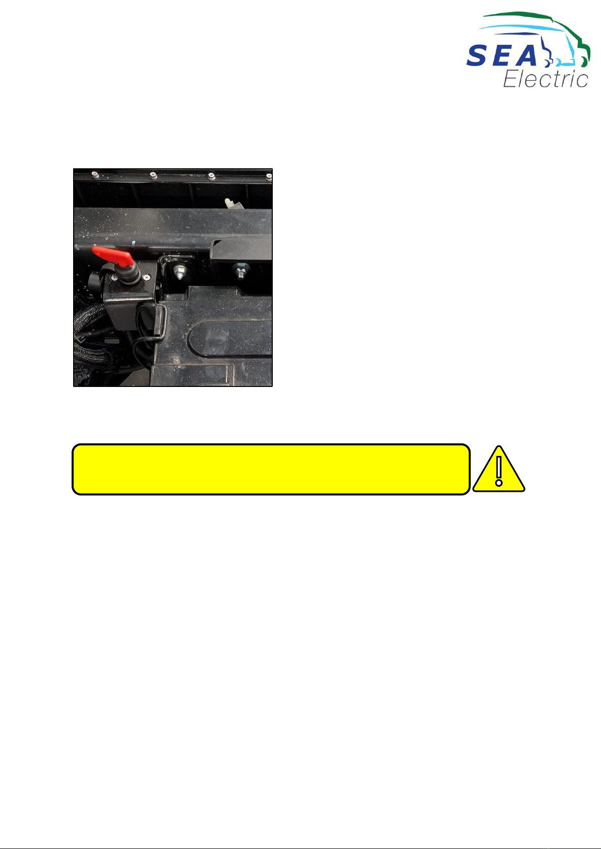
Low Voltage Isolation
The Low Voltage Isolation switch is located next to the low voltage batteries (Position of the
batteries is based on the truck chassis).
Never attempt to open a battery pack. This vehicle uses a battery pack
that operates at 450 volts DC.
Never attempt to remove, unplug or cut any of the ORANGE marked
cables or conduit. Orange marked cable carry high voltage.
Only authorised personnel are allowed to work on electrical power
and/or control systems.
DO NOT carry out any welding or other dirty works like grinding, etc. on the
vehicle without permission from SEA-Electric. Otherwise serious damage can be
caused to the drive train and the electronic control systems.
OWNER’S MANUAL (SEA ISUZU FSR/FSD EV)
SEA-OWS-QA-004/5 ISSUE DATE: 30/05/2020 Page 5of 56
The power from the traction batteries can be isolated by following this procedure:
1. Remove the ignition key.
2. Turn the 24V isolator switch to its vertical position.
24V Battery System Isolation Switch
Loss of Electrical Power during Operation
If the SEA-Drive® vehicle was to lose electrical power while the vehicle is in motion, the steering will
become stiff and the vehicle will continue to roll. The regenerative braking system will not assist
braking. Use of the park brake will affect braking on the rear wheels only.
IMPORTANT!! The traction battery pods will remain charged, even when switched off!
The battery pods will remain charged, even when switched off.
The leads and connectors on the pods will not be live if the pods are switched off.
This manual suits for next models
1
Table of contents


 Operator's manual")


