SeaCom SC410 User manual

SC4x0 Technical manual Page 1 of 34
SeaCom Rev 2.00
SC4x0 Technical manual
Abstract: This document is the technical manual for:
- SC410, a high-end flush mount telephone for wheelhouse & ECR.
-SC420, a high-end bulkhead mounted heavy-duty telephone for E.R. etc.
Doc ID:
Revision history
Date D.Rev. S.Rev. Init. Comment
2008 05 28 01.00 080409 LAF Document created...
2008 11 12 01.01 081106 LAF Document updated to new hands free funk.
2009 10 07 02.00 091007 LAF Busy detect, local external mode
SC4x0 Technical manual Page 2 of 34
SeaCom Rev 2.00
Technical Manual
-SC410 / SC420
- P410 / P420

SC4x0 Technical manual Page 3 of 34
SeaCom Rev 2.00
Contents
1. INTRODUCTION.............................................................................................................6
1.1 Purpose and Scope ....................................................................................................6
1.2 Required approval information....................................................................................6
2. Overview .........................................................................................................................7
2.1 Display ........................................................................................................................7
2.2 Display -Power on info................................................................................................7
3. Menu system ...................................................................................................................8
3.1 Menu levels.................................................................................................................8
3.2 Display modes ..........................................................................................................10
3.2.1 Display –Idle mode ............................................................................................10
3.2.2 Display –Busy mode..........................................................................................10
3.2.3 Display –Error mode..........................................................................................10
3.3 Call indicator.............................................................................................................11
3.4 Light sensor & backlight............................................................................................11
4. Data & control signals from the exchange.....................................................................12
4.1 Line voltage & ringing voltage detector.....................................................................12
4.2 16 kHz control signals...............................................................................................12
4.3 FSK / CLIP data........................................................................................................12
5. Hidden menu.................................................................................................................13
5.1 System info ...............................................................................................................13
5.1.1 Device & software family ...................................................................................13
5.1.2 Serial number ....................................................................................................13
5.1.3 Production date .................................................................................................13
5.1.4 System state......................................................................................................13
5.1.5 E bank ...............................................................................................................14
5.1.6 Error code..........................................................................................................14
5.2 Monitor line ...............................................................................................................14
5.3 Monitor input .............................................................................................................15
5.4 Set parameter xx ......................................................................................................15
5.5 Recall factory ............................................................................................................15
5.6 Erase eeprom ...........................................................................................................15
5.7 Reset ........................................................................................................................15
5.8 Sys test .....................................................................................................................15
6. Protective measures......................................................................................................16
6.1 Reverse voltage........................................................................................................16
6.2 Excessive voltage .....................................................................................................16
6.3 Excessive temperature .............................................................................................16
6.4 Program deadlock protection....................................................................................16
6.5 PCB coating..............................................................................................................16
7. Audio path & voice control.............................................................................................17
7.1 Acoustic considerations............................................................................................17

SC4x0 Technical manual Page 4 of 34
SeaCom Rev 2.00
7.2 Voice control considerations.....................................................................................17
8. Electrical layout .............................................................................................................18
8.1 Example of a simple set up with headset .................................................................18
8.2 Example of a simple set up with handset .................................................................19
8.3 Example of set up with remote PTT for loudhailer....................................................19
8.4 Ground & shield connections....................................................................................19
9. Mounting & programming ..............................................................................................20
9.1 Power supply & grounding considerations................................................................20
9.2 Programming the type of headset & VOX.................................................................20
9.3 Adjusting microphone gain .......................................................................................20
9.4 Relay function ...........................................................................................................21
9.5 Dial signal type .........................................................................................................21
9.6 Hands free voice control ...........................................................................................21
9.7 Bell signal and volume..............................................................................................21
9.8 PA volume ................................................................................................................21
9.9 External speaker.......................................................................................................22
9.10 Adjusting external dimmer input ...............................................................................22
9.11 Local external microphone........................................................................................22
10. Parameter list ................................................................................................................23
10.1 Level 1 parameters ...................................................................................................23
10.2 Level 2 parameters ...................................................................................................23
10.3 Level 3 parameters ...................................................................................................24
10.4 Parameter list for hidden menu.................................................................................25
11. Serial monitor ................................................................................................................27
11.1 Function....................................................................................................................27
11.2 Commands ...............................................................................................................27
11.3 Commands use full for workshop testing..................................................................27
11.3.1 Set Relay -command .........................................................................................28
11.3.2 To pass audio from microphone to speaker ......................................................28
11.4 Commands use full for development & testing .........................................................28
11.4.1 Memory monitor & manipulation........................................................................28
11.4.2 Eeprom data ......................................................................................................28
11.4.3 Busy tone detector.............................................................................................28
12. Simple faultfinding.........................................................................................................29
12.1 No ‘life sign’ ..............................................................................................................29
12.2 Spontaneous reset....................................................................................................29
12.3 Unable to hang up in hands free mode.....................................................................29
12.4 Noisy or scratchy sound quality ................................................................................29
12.5 No direct in, no PA or no command call ...................................................................29
12.6 Dialing problems .......................................................................................................29
12.7 Low or distorted sound from microphone .................................................................29

SC4x0 Technical manual Page 5 of 34
SeaCom Rev 2.00
13. Technical specifications ................................................................................................30
13.1 Connectors ...............................................................................................................30
13.1.1 Power ................................................................................................................31
13.1.2 PE protective Earth............................................................................................31
13.1.3 Line....................................................................................................................31
13.1.4 Dimmer ..............................................................................................................31
13.1.5 Handset & cradle ...............................................................................................31
13.1.6 Relay output ......................................................................................................31
13.1.7 External speaker................................................................................................31
13.1.8 Headset .............................................................................................................32
13.1.9 Cable & terminals ..............................................................................................32
13.2 General environmental data .....................................................................................32
13.3 I/O & signaling interface............................................................................................32
13.4 Cutout & mounting ....................................................................................................33

SC4x0 Technical manual Page 6 of 34
SeaCom Rev 2.00
1. INTRODUCTION
1.1 Purpose and Scope
This document is intended to give detailed information on the SC4x0/P4x0 telephone during
installation. Information given here is intended for skilled service engineers and if not use
correct, could lead to possibly malfunction.
This manual cover installation and setting up the telephone e.i. adjusting parameters etc.
1.2 Required approval information
P410 is an alias for SC410, P420 is an alias for SC420, where SC is short for SeaCom and P
is Phone( Alphatron label).
•The SC410 is intended for desk mounting in protected areas.
•The SC420 is intended for bulkhead mounting in protected areas.
•SC410 & SC420 are designed according to IEC 60945.
•Keypad is according to ITU-T E.161
•Compass safe distance: >7m.
•Software ID. : 2007001
•Software rev.: 091007
•All produced units are marked with type id and serial number.
WARNING
Do not disassemble the device as high voltage may present on the PCB or terminals.
Telephone line signal may contain voltage ranging from 48Vdc up to 130Vac peak.
Always switch off ALL power or disconnect ALL terminals before disassemble.
DO NOT REMOVE PROTECTIVE EARTH (PE) when device is operational.
ONLY CONNECT POWER TO SUPPLY TERMINALS & RELAY TERMINALS.
IF SUBJECTED TO EXCESSIVE CURRENT PCB MAY CATCH FIRE, THEREFOR
ALWAYS USE FUSED POWER SUPPLY ESPECIALLY ON RELAY TERMINALS.
PROTECTIVE MEASURES ARE TAKEN TO PROTECT THIS EQUIPMENT.
DEVICE WILL TRY TO DISCONNECT IT SELF BY SHORTING THE SUPPLY VOLTAGE IF
IT EXCEEDS 33V.
DEVICE WILL TRY TO DISCONNECT IT SELF BY SHORTING THE SUPPLY VOLTAGE IF
CONNECTED WITH REVERS POLARITY.
DEVICE IS INTERNALLY SEQURED BY A THERMAL FUSE OF 1.5A, HOWEVER. PEAK
CURRENT EXCEEDING 1.5A WILL OCCUR UNTIL FUSE IS TRIPPED.

SC4x0 Technical manual Page 7 of 34
SeaCom Rev 2.00
2. Overview
2.1 Display
The display is a 3 line 16 char dot matrix display with adjustable red backlight & automatic temperature
compensated contrast control. Display is shown in idle mode.
Display always revert to Idle mode after a general time out of 10 sec. When timing out, current process
is canceled. If timeout occurs during programming, data is lost and old data is restored.
2.2 Display -Power on info
When the phone is in power on state it will show information about hardware and what software it is
running.
4 sec. after power on display will enter idle state unless no line is detected.
After 4 sec.:
Display
Local Speaker
Call indicator
Speed dial / Function keys
Redial / Pause
R‐key
Local PTT
Light sensor
Menu key
Mem dial ke
y
Hands free Key
Speaker key
Local Mic.
Numeric keys
11/01 23:18 2
SPD1 SPD2 SPD3
Date & time Status field
Function key text
Info field
Vol. / Backlight
Menu navi
g
ation
00/00 00:00
SPD1 SPD2 SPD3
HW Rev. 01
SW Rev. 080104
SW ID.. 2007001

SC4x0 Technical manual Page 8 of 34
SeaCom Rev 2.00
3. Menu system
All adjustments and setup changes are made through the menu system. It is only possible to enter the
menu system if the phone is idle or if no line is connected. If a call is received or if phone is off hook
(active), all menu processes are aborted and display will show idle or busy status menu.
The menu system is divided in to two sections, user section & hidden section.
User section can be accessed directly from the keypad by pressing and holding down ‘M’.
Hidden section can be accessed by pressing ‘R’ 5 times with an interval between 0.5 – 1.0 sec on. If
another key is pressed or time is not within the window, operation is reset.
When the menu system is active and no keys are pressed, all operations will be canceled after 10 sec.
If data was being entered, operation is canceled and old data restored. If a call is received while
operating the menu system, immediate timeout is generated and the telephone will revert to idle to
show incoming call or idle state.
A few special menus are excepted from the general timeout. These are the dial function and some
monitor functions in the hidden menu.
3.1 Menu levels
There are 3 levels in the main menu system.
•Level 1 is common used settings. (volume, ringer level etc.)
•Level 2 is primary settings (memory dial setting etc.)
•Level 3 is secondary settings. (Settings used for installing the phone)
There is one level in the hidden menu.
If more detailed information re. the menu system is required, please refer to user’s manual.

SC4x0 Technical manual Page 9 of 34
SeaCom Rev 2.00
Level 1:EXIT
Speaker volume
Backlight
Ringer volume
P.A. volume
Bell signal
Calls out
Calls in
SET_UP_MENU
Level 2: Main Menu
Auto answer
Auto busy
Direct in
Hands free
External speaker
Date & Time
Speed dial
Memory 1-6
Special menu
Level 3: SET_UP_MENU
Dial signal
Loop dial type
Remote PTT
Remote Hook switch
Lcl Ext Mic
Headset type
Headset VOX.
Gain local microphone.
Gain handset microphone.
Gain headset microphone.
Gain external microphone. (loudhailer)
Relay mode.
Relay hold off.
Contrast (display)
Hidden menu: System Info
Monitor line
Monitor input
Set param. XX.
Recall Factory.
Erase EEPROM
Reset
Sys. test
SC4x0 Technical manual Page 10 of 34
SeaCom Rev 2.00
3.2 Display modes
When display is not used for display the menu system it will enter idle state or mode.
Idle mode is the initial display mode or basic mode. From idle mode it can enter dial mode, busy mode,
error mode or menu mode.
3.2.1 Display –Idle mode
When the telephone is in idle, display will show the following info.:
3.2.2 Display –Busy mode
When the telephone is in conversation mode e.i., the phone is busy, display will show the following
info.:
If mute state, speaker or hands free changes, status field is updated.
If change to another audio connection e.g. handset is made, it will be shown in the display.’
3.2.3 Display –Error mode
When the telephone detects missing line, it will enter error mode. Here the cause of current error will
be shown as flashing text or error code. Currently, only line error exits.
10/27 14:08 HS*
00:12:35
LOCAL
Status field
Leap time
Real time clock
Audio connection
Power
Menu System Idle mode
Busy mode
Dial mode
Error
11/01 23:18 2
SPD1 SPD2 SPD3
Date & time Status field
Function key text
00/00 00:00
No Line

SC4x0 Technical manual Page 11 of 34
SeaCom Rev 2.00
3.3 Call indicator
Call indicator has two purposes. Primary purpose is to indicate line state. Secondary purpose is to
indicate lost calls & system error.
•Off…………...: Line is idle.
•Rapid flashing.: Line is ringing.
•Steady light…: Line is busy.
•1Hz flashing...: Line or system fault.
•Short flash…..: Missed calls.
If flashing, but no line error is shown, a system error has occurred.
3.4 Light sensor & backlight
The light sensor in the front is used to control the backlight in the keyboard and display when backlight
mode is set to automatic.
The raw data from the sensor can be read out via the hidden menu.
If two units are placed side by side and dimming is controlled externally, dimmer input needs to be
calibrated for the two units to have same intensity.
NOTE: External dimmer is optional
The display and the keyboard light are controlled by a common function and variation in power supply
will a minimum impact on backlight intensity.

SC4x0 Technical manual Page 12 of 34
SeaCom Rev 2.00
4. Data & control signals from the exchange
Signals & data are sent from the exchange in different ways. Control signals are issued as 16kHz
burst, where the duration and current state of operation determine how to interpret date. CLIP signals
(Caller Line Information) are issued using FSK.
Line voltage is used to indicate ringing, busy or idle.
4.1 Line voltage & ringing voltage detector
The line interface fund in drawing SCH061212LAF01_xxx page 2 of 3 shows the line interface.
Line voltage and polarity is measured by the processor via U2A and the voltage divider placed across
the line.
Line Voltage
>25 volt dc Line is idle
<18 volt dc Line is busy
<5 volt dc No line
If AC voltage >25Vac @50Hz is detected (pure AC or AC on top of DC), ringing is detected.
There is a 200ms delay before a valid change of state is detected.
4.2 16 kHz control signals
The line interface fund in drawing SCH061212LAF01_xxx page 2 of 3 shows the line interface. 16kHz
signals are filtered through the high pass filter and passed into the detector. The detector input is
compare to a DC level set by the processor. From the hidden menu system, it is possible to adjust
trigger level for the detector. Only I rare cases where noise is disturbing the detector, adjustment of the
16 kHz threshold level is needed or if the detector needs to be disabled. Setting the level to 0% or
100% will disable the detector.
4.3 FSK / CLIP data
If the exchange is programmed to issue FSK data, caller’s ID can be displayed. Data is sent in a single
burst of 575 ms from the exchange, 500ms after first ring signal. FSK data is decoded by U19 and sent
as 1200 baud data 8N1 to the processor. The processor’s UART 1 picks up any FSK data. Up to 20
digits and 50 chars can be sent as caller’s number & name in a single message. The telephone will,
however show the last 16 digits only of the number and the 16 first chars of the name.
The telephone needs no power on / wake up ringing signal as it runs on constant power and never
enters any power down mode. This means data can be received without the need of an alert ringing or
signal sequence.
NOTE: Only month and day data is defined in the time data frame for CLIP data. If year info is needed,
it must be keyed in manually from the menu system. The internal RTC use year info for leap year info.
Default year will be 00. This will have a potential impact on the date shift from 28->29 of feb.

SC4x0 Technical manual Page 13 of 34
SeaCom Rev 2.00
5. Hidden menu
This menu is hidden, as all items in this menu are intended for service or setting up the unit. Some
settings in this menu can possibly cause the unit to malfunction e.g. setting audio gain to line to 0.
The menu access is protected by a times key sequence. The ‘R’ button must be pressed 5 successive
times at an interval of 0.5 – 1 sec. If timing is not right, the 5 time counter will reset.
5.1 System info
This sub menu item displays the following items:
•Device & software family
•Serial number
•Production date
•System state
•E_Bank
•Error code
5.1.1 Device & software family
This item has partly been replaced by the power up menu, but will show in plain text the basic type of
device.
5.1.2 Serial number
This item is the device unique serial number. If this number is missing, error is indicated via the call
indicator flashing and an entry is made to the internal error log.
5.1.3 Production date
This item shows the production date of the device. It should be on the format YY/MM.
5.1.4 System state
This item shows current device state. If an unrecoverable error is detected, device will enter error state
and start flashing the Call indicator.
It should read ‘2’ for normal.
State code State
0 Reset (debugging)
1 Boot (debugging)
2 Normal
3 Programming
4 Error
5 Manual (debugging)

SC4x0 Technical manual Page 14 of 34
SeaCom Rev 2.00
5.1.5 E bank
This item shows current NOV memory error info. If a check sum error is detected in an eeprom
memory bank, error state is entered and the ID of the last failed bank will be shown here.
5.1.6 Error code
If an error is detected, a new entry is made to the error log and last entry is shown here. If the device is
giving error indication, the cause should be identified here.
Each system error has a unique binary indicator. If more errors are present, error code will represent
the sum of all errors. The value 0 is no errors.
E.g. if error 0x0001 and error 0x0002 is both active, error code will show 0003
Error code Cause Function
0001 RAM error Set error state
0002 Check sum error
0004 NOV memory error Set error state
0008 Temperature alarm
(set if board temp. >
80°C)
0010 Temperature warning
(set if board temp. >
70°C)
Switch off all backlight
Decrease speaker vol.
to step 7. (44%)
0020 No serial number Set error state
0040 Watch dog error Set error state
0080 IRQ time too long
5.2 Monitor line
This item will monitor all line events. This menu will not exit idle when hook off or timeout. It is possible
to press ‘Speaker’ to go off hook or to call the phone.
Following items will be monitored. Display will update on change only
Line voltage: Numerical value from 0 to 63 volt.
Line polarity: Tip > Ring : 1, If Ring > Tip : 2. NOTE Voltage must be out of 5V dead band.
Line state: -Idle
-busy
-ring
-NC
16 kHz signal: -Vol. Indicating volume override (PA call).
-PA. Indicating normal PA call
-Term. Termination of ongoing sequence or cancel call.
-HOFF. Hook Off command (used for command / group call with direct in)
-HON. Hook On command (used for init of device or cancel command call)
-DIRECT Direct in call

SC4x0 Technical manual Page 15 of 34
SeaCom Rev 2.00
5.3 Monitor input
This item is mainly used for testing hardware. It will show input values from PTT, HOOK & sensors.
Temperature: -20 - +90° Displays actual board temperature.
Dimmer input: 0 – 100% Displays actual external dimmer input level.
Light sensor: 0 – 100% Displays actual light sensor level.
If signal from headset PTT or handset hook switch is detected, display will show coherent text.
5.4 Set parameter xx
This item is used to adjust all hidden parameters not accessible from the main menu system. Each
parameter is given as id number. The number can be found in the section ‘Parameter list for hidden
menu’.
First key the number of the parameter to change. When pressing ‘M’, display will show current value
for that parameter. If the value is not to be changed, just press ‘M’ to return. If a change is requested,
key in a new value using 0-9. If range is 0-9, only one digit can be entered. To enter the new value,
press ‘M’.
If the new value is out of range, data will be replaced by high or low boundary value.
Depending on the type of data, ‘.’ Or ‘-‘ can be entered using the F-keys. F3 will erase last entered
digit.
5.5 Recall factory
This function will clear all user settings and restore them to factory values.
Use this function if there is any doubt re. current settings, to set all parameters.
From software 090928, all new parameters will automatically preset to factory values on first power up
after software update.
When updating software, it is always a god idea to note deviations from factory settings before
recalling.
Especially if adapted for special use.
NOTE: memory & speed dial data will NOT be erased by this function.
5.6 Erase eeprom
This function will erase all settings, all speed dial data, all mem dial data and call logs and cause the
unit to reload factory settings to all parameters on first power up
5.7 Reset
This function will cause the device to restart as if power was recycled. Use this function to read current
software rev., hardware rev or software id from the power up menu.
5.8 Sys test
This function will engage a small test sequence to test alarm relay and display.
Will revert to idle after 10 sec.

SC4x0 Technical manual Page 16 of 34
SeaCom Rev 2.00
6. Protective measures
6.1 Reverse voltage
The device is protected against wrong polarization of the supply voltage. In the supply line a protective
diode is connected across in non-conducting direct when connected right. When connected in reverse,
this diode will short through a PTC fuse and interrupt the supply current.
Supply must be disconnected for a few seconds before the fuse resets.
6.2 Excessive voltage
The device is protected against high voltage from e.g. battery charger. If the supply voltage exceeds
approx 33.5 volt a crow bar circuit will short the supply through a PTC fuse. This will either blow the
external fuse or lower the internal supply to below 0.5 volt until supply is disconnected.
Supply must be disconnected for a few seconds before the fuse resets.
6.3 Excessive temperature
If the board temperature exceeds 70°C a warning is given to the internal alarm log and error condition
is indicated by the ‘Call’ indicator.
If the temperature exceeds 85°C an alarm is given, backlight supply is disconnected if the unit is active
volume is lowered to step 7 if set higher for reducing the power dissipation.
When temperature of the power amplifier reaches approx 140°C it will shut down due to thermal
protection.
6.4 Program deadlock protection
The processors internal watchdog that is enabled at a rate of 106ms protects the device software.
It is only serviced by the main loop and a few time-consuming inline functions. In case software
accidental or by electrical noise injection enters a deadlock a timeout will occur and reset the
processor.
In parallel to that, an optional external watchdog can be enabled by means of a jumper in J7. If a
jumper is located in pos no. 3 from left to right, the watchdog is enabled. If the jumper is omitted, it is
disabled.
The external watchdog is for future implementing of PA and other options requiring an independent
monitor source and is have a service timeout of 1,6 sec.
6.5 PCB coating
The PCB is coated to protect it from the harsh environment at sea.

SC4x0 Technical manual Page 17 of 34
SeaCom Rev 2.00
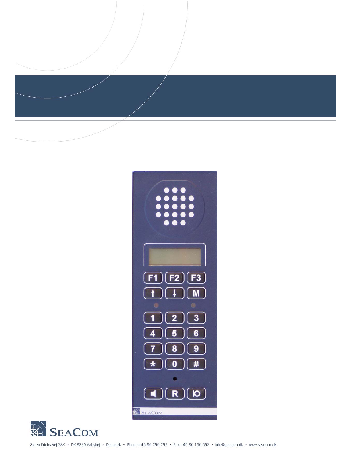
7. Audio path & voice control
Below a schematic of the audio path is shown.
All audio is passed through the codec for signal processing. Volume control of the speakers and pre-
gain control of the microphones are all made via processor control. There are no mechanical
adjustable.
All microphone inputs are balanced inputs for maximum noise suppression.
7.1 Acoustic considerations
To select the right setup for the installation is important to optimum sound quality.
In general, hands free works best in quiet areas, but if an external speaker is added it could be
functional in areas with moderate ambient noise.
If installed in areas with a very high level of ambient noise, headset is the only right solution.
Care should be taken to select headset or handset capable when making installations in high noise
areas.
If the microphone sensitivity is too high, it might suffer from signal saturation or cause the input to
suffer for saturation.
Location Ambient noise
level
Operation
Bridge, Offices, Mess, etc Low Hands free, handset.
Voice control: 10dB .. 25dB
ECR, Galley, SCC Medium Hands free, handset, possibly assisted by
external speaker.
Voice control: 30dB .. 40dB
ER, SGR, Generator High Handset, headset.
Thruster, Hydraulics Very high Headset and in some cases handset.
7.2 Voice control considerations
To get optimum performance from the automatic voice control when using hands free, the level of
speech must be approx. 10dB above background noise level. If not, voice control cannot detect voice
from noise and thus control direction of speech.
This is very important when using headset or hands free in every noisy areas, especially when using
headset in extreme noisy areas in one end and hands free at the other end, even more if combined
with VOX for the headset.
To be able to go above the background noise level, may require a high sound pressure that will
saturate the microphone input if the microphone is too sensitive or if the gain is too high.
Line
Handset
Handset
Local
Local
Headset
Headset
Ext. speaker
CODEC
yP control

SC4x0 Technical manual Page 18 of 34
SeaCom Rev 2.00
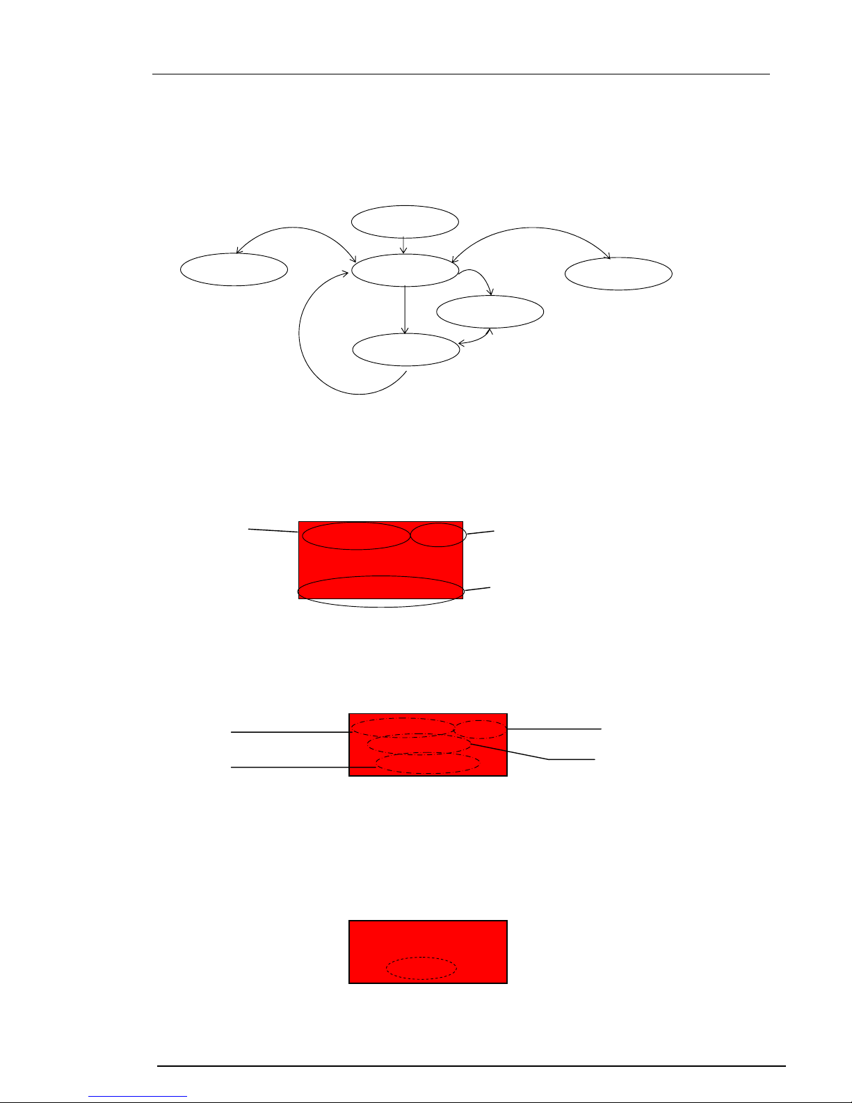
8. Electrical layout
Below a schematic of the electrical layout is shown.
The drawing below shows all connections and number of wires.
8.1 Example of a simple set up with headset
This example shows how to connect supply & headset to the telephone.
+24V
Frame
PE
Dimme
r
0V
Hook SW 0V
Hook SW
Power Amp. DC/DC
0V
+5V
Line Ti
p
Ring
PTT
S
p
eakers
Mic.
Display
Keypad
Line
+24V
Dimmer
(optional) 2
2
2
2
6
6 2
Headset
Handset
Ext. speaker / Loudhailer
PE
Headset SP
Headset PTT
Headset Mic
SC410/420
+24V
0V
Relay COM
Relay NO (or NC)
PE
T1A
T2A
PE
NOTE: If shield is connected at
APBX do NOT connect to PE at
telephone end
Always only connect one end due
to possibly high ground current
when
used off shore
To bell or alarm relay coil
NOTE: If connected to DC
coil
–
use
p
rotection diode.
Line

SC4x0 Technical manual Page 19 of 34
SeaCom Rev 2.00
8.2 Example of a simple set up with handset
This example shows how to connect supply & handset to the telephone.
8.3 Example of set up with remote PTT for loudhailer
This example shows how to connect loudhailer in remote location
8.4 Ground & shield connections
It is very important to connect or terminate all shields correct. Normally shields should be terminated to
ground or ship hull in both ends and not carry any signal (forward or return). Due to possible high
ground currents in case of earth leakage or lower shield resistance, it recommended to terminate in
one end only.
In general, power and line should be terminated at the exchange and remaining wires at the
telephone.
It is very important to connect ‘PE’ to ground or ship’s hull for protection and to avoided noise
interference. Connection between ‘PE’ and ground should be as short as possible.
PE
Handset SP
Hook Sw. signal
Handset Mic
SC410/420
+24V
0V
Relay COM
Relay NO (or NC)
PE
T1A
T2A
PE
NOTE: If shield is connected at
APBX do NOT connect to PE at
telephone end
Always only connect one end due
to possibly high ground current
when
used off shore
To bell or alarm relay coil
NOTE: If connected to DC
coil
–
use
p
rotection diode.
Hook Sw. 0V
Cradle switch must be potential
free.
Switch must close when handset is
off hook.
Cradle Switch is connected to Hook
Sw. on telephone
If cradle have a double switch, use
the other for connecting speaker.
PE
Headset PTT
Ext. Speaker
Headset PTT function needs to
be assigned to loudhailer PTT
from the menu s
y
stem.
NOTE: When using headset
PTT for remote loudhailer,
due to noise picked up by the
cable, adding a slave relay
located next to the telephone
may prove beneficial.
Line
Line

SC4x0 Technical manual Page 20 of 34
SeaCom Rev 2.00
9. Mounting & programming
When setting up this unit, first disassemble the box if it is a 420 type.
Detach the terminals J4 & J6 by pulling them off. Connect all wires to the terminals and check power
and relay connections before attaching the terminals to the unit. Be careful not to relocate J4 at J6.
9.1 Power supply & grounding considerations
If powered from the exchange, make sure a fuse protects the unit and power supply is strong enough
to blow the fuse without shutting down the exchange. If more units are connected, make sure the
power supply has enough dynamic power to handle peak currents if external speakers are connected.
The telephone will consume approx 250mA max if no external speaker is connected. An 8ohm
speaker will take additional peak currents up to at least 1.8 amp.
Both the 410 & the 420 must have connected PE via a separate wire to a central earth/grounding
point.
9.2 Programming the type of headset & VOX
When using headset, always check the type of microphone. If it comes with an eletrect (condenser)
type, changes needed to be made to factory settings. Enter the menu system to select matching type.
Always make gain adjustments AFTER selecting type of microphone.
The headset can be used with full duplex or in PTT mode. However, in full duplex mode when
connected to another phone using hands free, some voice control may be needed to maintain control
of speech direction.
VOX will raise or lower gain towards the line for better speech detection at the hands free end. This
will enhance the speech quality by raising the gain when speaking into the headset microphone and
lower it when not. If voice switching is used at the hands free end, it will ease the detection of speech.
However, if speaking at the same time, it may difficult to hear what is said at both ends, so it requires a
little practice to learn to speak in shift for perfect connection.
9.3 Adjusting microphone gain
A key issue for best performance is correct adjusted microphone gain. This phone is designed for use
in very noisy areas but may just as well be used In quiet areas. However, this dynamic span can only
be achieved by adapting the microphone gain to the actual installation.
In most cases factory settings will work just fine. However, if used in noisy areas, gain must be
lowered to avoid distortion and signal saturation. A high level of background noise requires the user to
speak very loud.
When speaking very loud the microphone generates accordingly higher signals that not need the
same amount of gain.
For the hands free voice control to work as intended, any distortion must be eliminated. This is the
reason why microphones gain need to be adapted, especially in areas beyond normal office
conditions.
Likewise if used in quiet areas or for remote listening.
This manual suits for next models
1
Table of contents


