Seafloor HydroLite-TM User manual
quick start guide/user manual
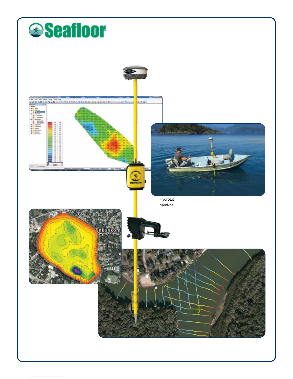
HydroLite-TM surveying in lake using a GPS antenna and
hand-held data collector.
Above, Right:
Singlebeam images courtesy
cbec Inc. eco engineering,
Sacramento, CA.
Singlebeam survey image courtesy of
Rice Associates, Manassas, VA.
HydroLite-TM™
A quick start guide/user manual.

quick start guide/user manual
Table of Contents Page Number
1. Introduction..............................................................................1
2. Equipment Supplied................................................................1
3. Options.....................................................................................1
4. Getting Started.........................................................................2
5. Things to check before calling Technical Support...............2
6. Troubleshooting ......................................................................3
7. Removing the transducer from HydroLite-TM......................3
8. Contacting Technical Support................................................3
Appendices—List of Reference Tools
HydroLite-TM Schematic
SonarMite MILSpec/SonarM8 User Manual
Sound Velocity Chart of Freshwater/Seawater
SonarMite Adroid Bluetooth App
Trimble Survey Controller/Access
Trimble Terrasync Setup
Trimble SCS900 with SonarMite Echosounder
Trimble Access Drivers for DFX
Carlson SurvCE
Leica Viva
Leica 1200
Topcon Magnet GNSS and Depth Sounder
HydroLite-TM™
Table of Contents
HydroLite-TM Quick Start Guide/Manual | Rev 08/11/2016
quick start guide/user manual
https://www.youtube.com/watch?v=SmnCkbmXiGI
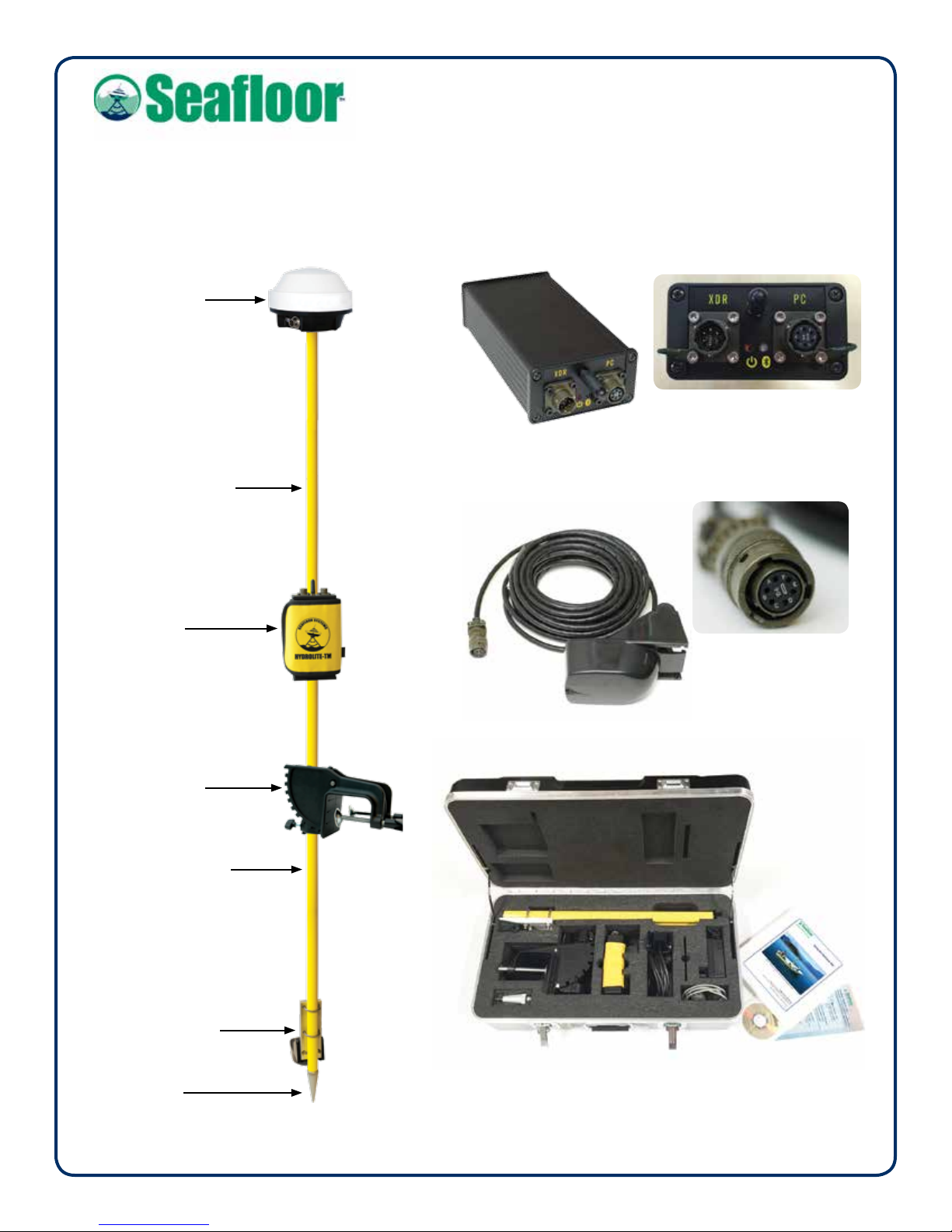
2. Equipment Supplied
•HydroLite pole kit
•SonarMite MILSpec Bluetooth echosounder
internal battery
Bluetooth™
IP65weatherproong
MILSpec connectors and caps
•200 kHz echosounder transducer
digital smart transducer
7-degree beam
bottom tracking technology
QA sonar strength signal
breakaway design
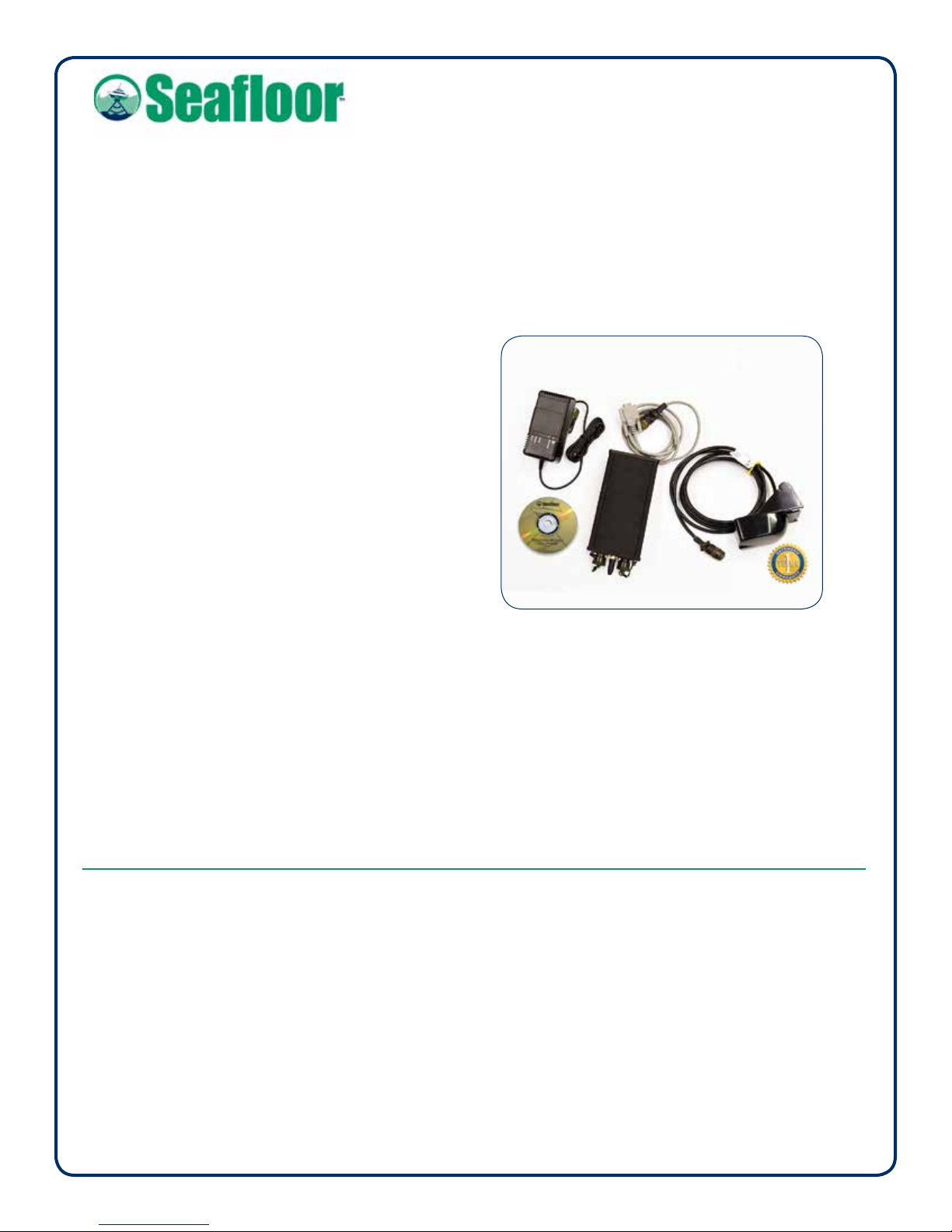
•12-volt power supply/charge
rapid charge
discharge feature
charge disconnect when battery is fully
charged
HydroLite-TM™
1. Introduction
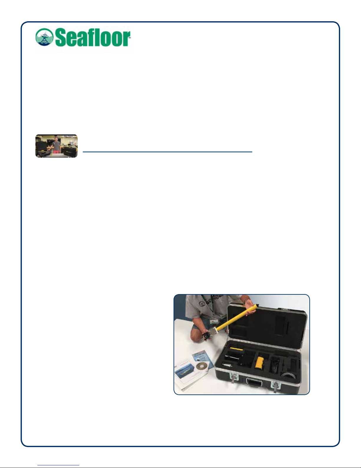
The HydroLite-TM (Transom Mount) Survey Pole Kit provides an integrated survey solution, allowing easy
mounting of the SonarMite echosounder. The YouTube setup video demonstrates how to assemble the
HydroLite-TM pole kit. At the very least, purchasing the mounting bracket makes faster surveys.
HydroLite-TM System in rugged carry case
•Serial interface cable
used for data transfer
•Quick Start Manual, including
Sound Velocity Charts: Freshwater / Seawater
setup guides for GPS antenna by
manufacturer
•training CD-ROM
user manual
other programs
•1-year warranty parts & labor
Page 1
HydroLite-TM Quick Start Guide/User Manual | Rev 08/11/2016
3. Options
•GPS antenna
•datalogger
•software
•sidescan sonar
4. Getting Started
4.1 Assemble the pole kit
Assemble the pole kit and attach to the boat. The pole
should be as straight as possible. The transducer
should be in water before turning it on.
4.2 Plug in the transducer
Plug the transducer into the echosounder. The red
light will ash (continuously) twice within a second,
indicating that the echosounder is turned on. The
transducer should be lower than the bottom of the boat.
Ifitisnot,thehullcouldreectreturnsoundings.
4.3 Attach the GPS antenna
Attach the GPS antenna to the top of the pole and turn
it on. Give it 2-10 minutes to track satellites. Ensure the
GPS antenna has a clear view of the sky at all times.
4.4 Set the device
DependingontheGPS/datacollector,followtheappropriatestartupguideforthatspecicsystem;i.e.,ifusing
Trimble Access, refer to the Trimble Survey Controller/Access appendix.
5. Things to check before calling technical support
5.1 Position of HydroLite-TM Pole:
Is the pole as straight as possible? Is the transducer in water and lower than the bottom of the boat?
5.2 Is there a blinking red light on the faceplate?
5.3 Is the transducer making a ticking sound?
If not, unplug the transducer, then plug in again.
5.4 Bluetooth:
If using Bluetooth, is there a solid blue light on the faceplate? If not, check Bluetooth pairing and connection.
5.5 Serial Connection:
Baud rate = 4800
For models prior to 2012: Baud rate = 9600
5.6 Data format:
Ensure you are using the correct data output format—should be “Old SonarMite Format”. Refer to SonarMite
User Manual. Be patient with the data collector—multiple taps could freeze it up.
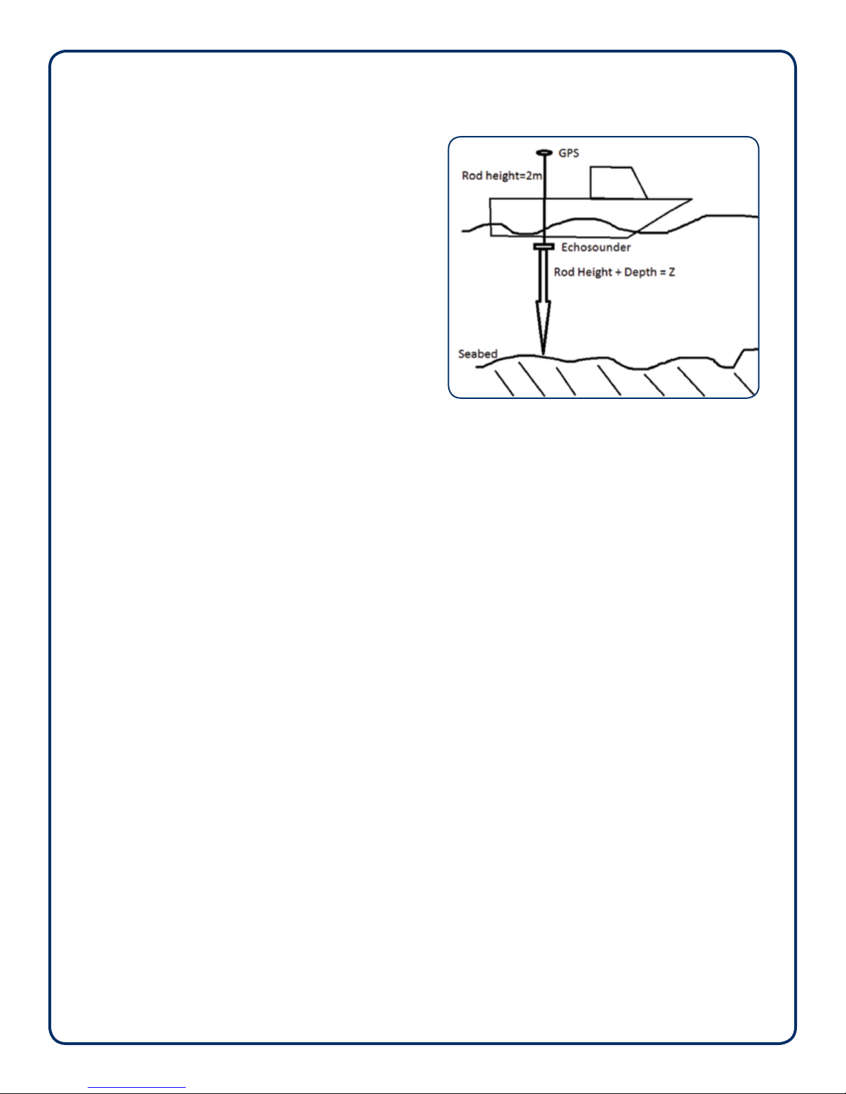
Typical setup for using the HydroLite-TM
Page 2
HydroLite-TM Quick Start Guide/User Manual | Rev 08/11/2016
Seaoor Systems, Incorporated
4415 Commodity Way, Shingle Springs, CA 95682 · USA
(530) 677–1019 | info@seaoorsystems.com | www.seaoorsystems.com
©2016 Seaoor Systems, Inc. All rights reserved.
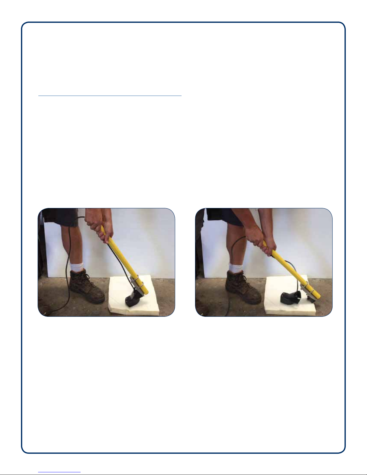
7.A: Place transducer on protective pad. 7.B: Press down rmly until it releases.
7. Contacting Technical Support
Call(530)677-1019orEmail:info@seaoorsystems.com
Monday-Friday,8:30a.m.-5:00p.m.PacicTime
6. Troubleshooting:
If the system is not working properly after checking steps above, use these tools:
6.1 PC:
Download Troubleshooting Tools can be found in the wcom32.exe app:
www.seaoorsystems.com/support/software-support
6.2 Android:
Basic troubleshooting (90% of issues) can be solved through the SonarMite App and more advanced issues can
be resolved used SENA BTerm, found on Google™Play Store.
7. Transducer Removal from HydroLite-TM
To remove the transducer, unscrew the section containing the transducer from the remaining pole kit. At a
45-degreeangle,placethetransducerheadonaprotectivepad,andpressrmlyuntilitreleases.
To view on YouTube:
https://www.youtube.com/watch?v=6MqtkR7Q0SE
Page 3
HydroLite-TM Quick Start Guide/User Manual | Rev 08/11/2016
quick start guide/user manual
HydroLite-TM in rugged carry
case with Quick Start Manual
SonarMite-MILSpec
singlebeam echosounder
Transom Mount
Survey Point
Pole Transducer
Mounting Bracket
HydroLite-TM™ Schematic
GPS Antenna
(optional)
SonarMite
Echosounder
in Velcro™Pouch
2-Foot Pole Section
2-Foot Pole Section
Transducer
Pg 1 of 1
user manual SonarMite MILSpec/SonarM8
Introduction
The SonarMite MILSpec and HydroLite-TM were designed to be an ultra-portable, survey-grade, self-contained
bathymetric survey system. The internal battery, Bluetooth, and easy integration make it popular with survey and
engineering companies.
options
•HydroLite-TM pole kit
•custom case
•GPS
•datalogger
•software
•sidescan sonar
Equipment Supplied
•SonarMite MILSpec Bluetooth echosounder
internal battry
Bluetooth
IP65weatherproong
MILSpec connectors and caps
•200 kHz echosounder transducer
digital smart transducer
7-degree beam
bottom tracking technology
QA sonar strength signal
breakaway design
•12-volt power supply/charge
rapid charge
discharge feature
charge disconnect when battery is fully charged
•serial interface cable
used for data transfer
•training CD-ROM
user manual
other programs
•1-year warranty parts & labor
Getting Started
TheSonarMiteMILSpecechosoundercanbeusedinmultiplecongurations:
•log into HYPACK or other hydrographic survey software on laptops
•using DGPS
•RTK GPS
•Survey Topo software on data collectors
•SM Mobile software
•remotely controlled unmanned boats
•robotic total stations
Page 1
SonarMite MILSpec/M8 User Manual | Rev 07/22/2016
Step 1—Switching the system on
Pluginthetransducercabletothecontrolbox;lookfor
a blinking red LED light. Red light indicates the system
is on and outputting depths. The transducer MUST be in
water to output depths.
Step 2—Connect to Bluetooth
When the system is powered on and the red light is
blinking, a Bluetooth connection can now be connected
using instructions from your collection device of choice
(refer to your data collector manual). When the Bluetooth
connection is enabled, a solid blue LED light will appear.
Step 3—Connecting the serial cable
A serial cable is included to output data from the
SonarMite. The transducer must be connected and a
red LED light blinking to output data.
Step 4—Data Collection
The SonarMite has eight output formats, depending on
the software used for data collection. Instructions for
changing the format and sound velocity is covered in
Step X. Please visit our website support section for the
specicsetupguidesforyoursystem:
http://www.seaoorsystems.com/support.html
Step 5—Bar checking
Bar checking is calibrating the system for the sound
velocity of the water being surveyed. There are two
methods of doing this:
5a. digital bar check (example Odom Digibar Pro)
5b.build abar checkconsisting ofa at,large baseat
axeddistancefromthetransducer.Forshallowwater,
sound velocity tables can be used to set the SonarMite
to a desired setting. To do this, obtain water temperature
from mid-water column, and refer to proper sound
velocity table for fresh or salt water. For questions, call
our support line.
Note:usingtheseabedforcalibrationisnotacceptable;
this should only be used for rough check.
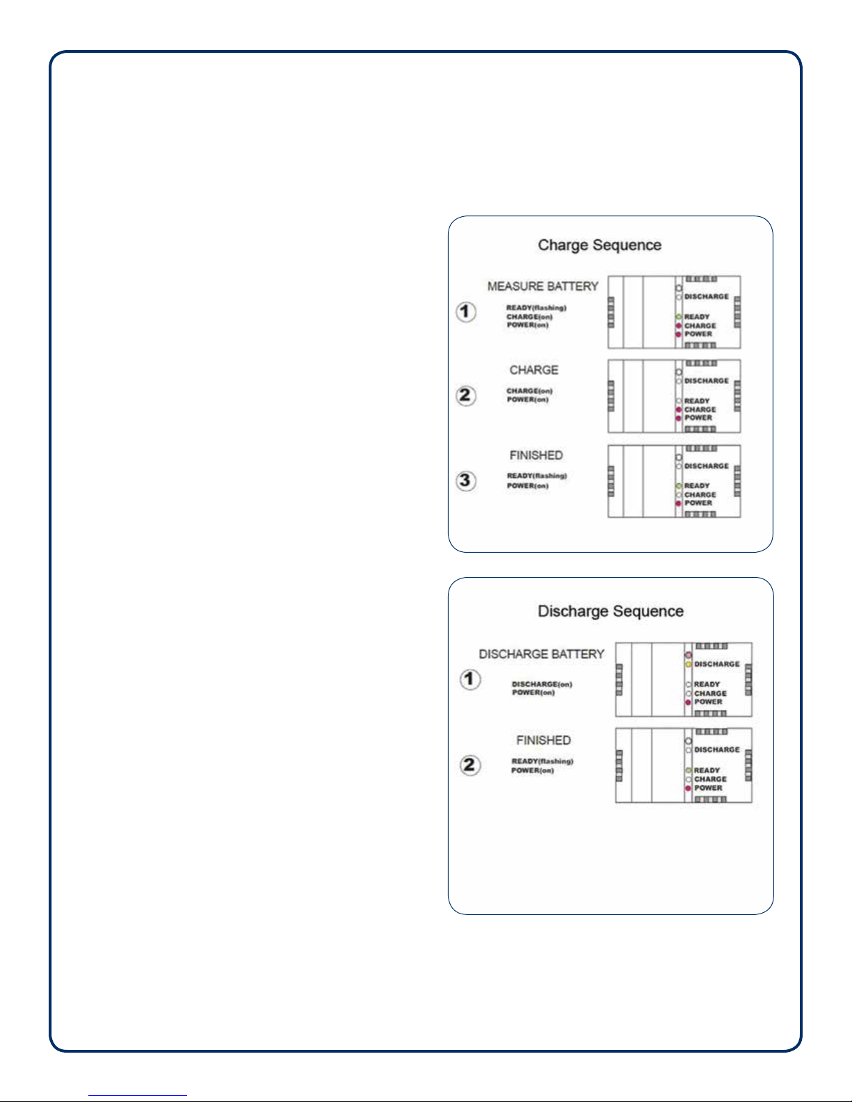
Step 6—Internal battery charging
Fully charge the battery, overnight, prior to using
the system. A full discharge and recharge should be
conducted every six months. Refer to the charge/
discharge illustrations.
Page 2
SonarMite MILSpec/M8 User Manual | Rev 07/22/2016

Step 7—SonarMite settings
The next few pages describe several output data formats
as well as how to change them and change the sound
velocity.
7a. Place transducer in water, such as a small bucket.
7b. Insert transducer connector to SonarMite control
box. Look for blinking red light.
7c. Connect to terminal program:
7c1. SENA BITERM via Bluetooth:
http://seaoorsystems.com/pdf/sena_bterm.pdf
7c2. WCOM32 Bluetooth or serial to laptop.
(Software is included on SonarMite CD ROM)
7d. View streaming data:
Control-F: cycles through the output formats below
Control-S: saves the output format
Control-R: resets the system to default output (the
unit MUST be in system format for
this to work.)
7d1.FormatOldSonarMite
(examplebelow)
1 0.48 0 0 0 8.9 115 0
1 0.48 0 0 0 8.9 115 0
1 0.48 0 0 0 17.8 116 0
1 0.48 0 0 0 8.9 115 0
1 0.48 0 0 0 8.9 115 0
“Old SonarMite” format is the defaul format used by
Trimble, Carlson, SM Mobile and HYPACK.
0.48 represents the depth.
8.9 represents the volts output of the internal
battery.
115 represents the sounding return quality number
from 70 to 135.
7d2.FormatASCIImode
(examplebelow)
0.48
0.48
0.48
0.48
0.48
0.48
0.48
ASCIImodeismainlyforLeicausers;
0.48 represents the depth.
7d3.Format2DBTNMEAmode
(examplebelow)
$SMDBT,1.6,f,0.48M,,#5C
$SMDBT,1.6,f,0.48M,,#5C
$SMDBT,1.6,f,0.48M,,#5C
$SMDBT,1.6,f,0.48M,,#5C
$SMDBT,1.6,f,0.48M,,#5C
$SMDBT,1.6,f,0.48M,,#5C
This is a standard NMEA output which can be
used with various logging software.
7d4.Format4OdomSBTmode
(examplebelow)
et 47
et 47
et 47
et 47
et 47
et 47
7d5.Format5Deso25mode
(examplebelow)
DA 0.48 m
DA 0.48 m
DA 0.48 m
DA 0.48 m
DA 0.48 m
DA 0.48 m
Page 3
SonarMite MILSpec/M8 User Manual | Rev 07/22/2016

7d6.Format6Polledmode
(examplebelow)
This will be blank.
7d7.Format7modeforsystemsettings
(examplebelow)
SYS> 54 0.48 109 109 0 116 1500 0.2 0
SYS> 54 0.48 109 109 0 116 1500 0.2 0
SYS> 54 0.48 109 109 0 116 1500 0.2 0
SYS> 54 0.48 109 109 0 116 1500 0.2 0
SYS> 54 0.48 109 109 0 116 1500 0.2 0
SYS> 54 0.48 109 109 0 116 1500 0.2 0
SYS> 54 0.48 109 109 0 116 1500 0.2 0
This is the system format.
Sound velocity output can be changed using
this method:
Control-U: increases from the default 1500
Control-D: decreases in increments of 10
When satisfied with sound velocity:
Control-S: save
Control-F: to reach desired output format.
Control-S: save again
Completed.
7d8.Format8NewSonaraMiteformat
(examplebelow)
1 0.48 8.9 115 0
1 0.48 8.9 115 0
1 0.48 8.9 115 0
1 0.48 8.9 115 0
1 0.48 8.9 115 0
1 0.48 8.9 115 0
1 0.48 8.9 115 0
New Sonarmite is currently for in-house
testing only.
Step 8—Using SonarMite/HydroLite-TM
in the eld
The HydroLite-TM pole kit provides an integrated
survey solution, alowing easy mounting of the
SonarMite echosounder. The YouTube setup video
demonstrates how to assemble the HydroLite-TM pole
kit. At the very least, purchasing the mounting bracket
makes faster surveys.
www.youtube.com/watch?v=SmnCkbmXiGI
8a. After the HydroLite-TM has been assembled, it
isimportanttondthebestlocationtomounton
the vessel. Over the side is usually preferred.
Aeroration from the engine in the rear can
disrupt soundings. The transducer should be the
lowest point of the vessel. When measuring for
offset of the rod height, begin at the bottom of
the transducer.
8b. The pole should be positioned as straight as
possible. This may change when the operator
or passengers are on the vessel. It is always a
good policy to note the draft of the transducer.
8c. Typical survey speed in between two and four
mph. The slower that the vessel is traveling, the
more soundings can be logged. Surveying in
a grid format is the best way to ensure proper
coverage of the survey area.
Page 4
SonarMite MILSpec/M8 User Manual | Rev 07/22/2016
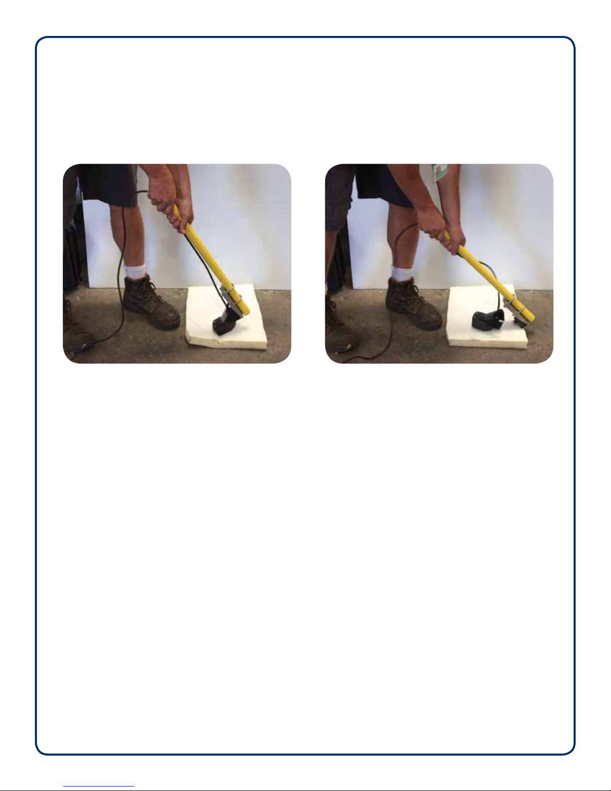
Transducer Removal from HydroLite-TM
To remove the transducer, unscrew the section containing the transducer from the remaining pole kit. At a
45-degreeangle,placethetransducerheadonaprotectivepad,andpressrmlyuntilitreleases.
A—Place transducer on a protective pad. B—Pressdownrmlyuntilitreleases.
Page 5
SonarMite MILSpec/M8 User Manual | Rev 07/22/2016

F.A.Q.
Isdualfrequencyrequired?
Dual frequency echosounders were originally designed for use by sea going vessels to report reliable, low
frequency depths in deep water situations, and more accurate, high frequency navigation within shallow areas.
Low frequency is of limited use in shallow hydrographic surveys Reasons are as follows:
•physicalaccuracyisoutsideIHOspecications
•power consumption prohibits true portable use
•minimum depth possible outside survey requirements
Canmudthicknessbemeasuredwithdualfrequency?
The residual difference between low and high frequency shown on an echogram gives the impression that mud
thickness can be measured. In fact, the trace gives an impression of soft sediment. However, in most sounders,
thisisthedifferenceinreectedenergyasaresultofsimplepenetrationofhigherpowerlowfrequencysignals
plotted against the low power high frequency returns.
Tomeasuremudthicknessandavoidlitigationonwrongresults,thesurveyorshoulduseequipmentspecically
designedforgeophysicalmeasurementssuchasasub-bottomproler,penetrometer,seismographorasimple
bottom sample.
Isabarcheckingrequired?
Many older technology echosounders needed to “warm up” before they became stable. In addition to their
internal frequency/timing circuits, varying with ambient conditions, the physical parameters that effect speed
of sound in water also varied with location. The accepted solution was a ‘’barcheck’’—where a large plate was
loweredinaspeciedsequencewherethedepthmeasuredbytheechosoundertotheplatewascompared
with an absolute stave or tape measurement. This method ensured that all variable parameters were included
in the calibration, as a gross check the barcheck was normally also performed at the start and end of a survey.
There are several problems with this method:
•The location of the barcheck is only relevant to the water column at that particular barcheck location and time.
•Olderanalogueechosoundersgavetheuserfacilitiesto‘’ddle’’withmanyparametersduringthesurvey,
modern digital sounders do not expose settings such as gain and threshold.
•Older instruments do not record changes to instrument settings during the survey.
•Narrow beam sounders with bottom detection algorithms can misdetect the moving plate.
•Modern digital electronic timing components are very accurate and stable.
There is still a requirement for calibration of sound velocity, but if required, this should be measured using a
calibratedsoundvelocityprobeloweredthroughthewatercolumntobuildavelocityprole.
A simple equivalent of the barcheck is to accurately visit with several locations within the survey area which
have a known elevation, normally derived from GPS and a weighted tape. These points should be used as a
reference throughout the duration of the survey.
Page 6
SonarMite MILSpec/M8 User Manual | Rev 07/22/2016

Shouldpitch/rollanglebeappliedtothedepth?
Many surveyors assume that sonar is like a laser being shone through the water and that the distance measured
should be assumed is a hypotenuse measurement to be trigonometrically corrected by any pitch/roll angle that
has been measured.
The best physical analogy of the echo sounder beam would be a torch light beam that is shone over an area,
withinthatareathereisasmallpieceofmirrorthatreectsthelightatthatpoint,sonarisverysimilarexceptthat
thereectedpointisnormallytheclosestpointwithinthebeam.
Whatisanarrowbeamtransducer?
The properties of a transducer are normally a function of its physical size/shape and its resonant frequency.
The beam pattern of a given transducer is normally presented as a radial distribution pattern versus output
power applied. This generally means that the spread (beamwidth) of the transmitted ultrasound increases with
amplitude. Most modern echosounders use a digital signal processing (DSP) technique to reduce the power/gain
of its transmitted signal and thus maintain the minimum beam width for a given transducer.
The advantage of a narrow beamwidth survey transducer is the ability to “see” into narrow valley shapes thus gain
aclearerrepresentativedenitionofthebottomsurfacebeingsurveyed.Thisiscontrarytothenavigationuse
of an echosounder, which has a reasonably wide beamwidth, where the returned signal within the beam is the
‘’shoalest’’ or shallowest point within the beam, obviously of more interest for hull clearance requirements.
Ismyshnderokayforsurveyuse?
Modernshnder typenavigationechosoundersuse quitesophisticatedDSPtechniquestoshow thebottom
surface,bottomtype,andshinthewatercolumn.Aswiththebeamwidthdiscussiontheelectronicsofa‘leisure’
shndersarenotdesignedforasurveyapplication.Inparticular,thedepthvaluesareeitherheavilyaveraged
to show a smooth transition in numeric depth values or are optimized to show the shallowest depth seen in
theparticularbeamarea.Similarly,surveyechosoundersmakeeffortstoremoveanomaliessuchasshswim
bladderreectionsfromthemeasureddata.
DoIrequiremorepingspersecond?
Assuming the pings all return good values, the advantage of more pings per second is that the survey boat can
travel faster and therefore cover much larger areas in a shorter time. The assumption that more pings provide
higher quality dense survey data is not so. Density is a function of boat speed and is constrained by the limitations
of transducer beamwidth as discussed above. More pings can also create more noise with the high degree of
insonarationinthewater,particularlyinshallowwatersituationswithmultipathreections.
Whatislatency?
Latency is the time difference between a position and depth being recorded. The topic is extremely complex and
can included some of the following sources of error:
•GPS position correction source time differences
•Timeofightofultrasoundinwater
•Serial transmission of data to, from and through computer systems
•Physical mounting of antennas and transducers In general the survey software attempts to minimize the error
by recording a precise timestamp on each piece of data recorded, the sum of all latency sources can then
be calculated by post-process adjustment of the data using a ‘’patch test’’ algorithm. The degree of latency is
dynamic so is always a function directly related to speed of the boat when data acquired, faster the boat then
more potential latency.
Page 7
SonarMite MILSpec/M8 User Manual | Rev 07/22/2016

Seaoor Systems, Incorporated
4415 Commodity Way, Shingle Springs, CA 95682 · USA
(530) 677–1019 | info@seaoorsystems.com | www.seaoorsystems.com
©2016 Seaoor Systems, Inc. All rights reserved.
Whataffectssoundvelocity?
The speed in which sound travels through water is directly proportional to the density of the water. The parameters
which change the density are:
•turbidity—the amount of sediment in suspension within the water
•salinity—the amount of substance (normally salt) dissolved in the water
•temperature—the temperature of the water sample
•temperature—sum of water depth and barometric pressure
All of the these parameters can vary considerably in any particular water column, but the assumption made with
a singlebeam echosounder is:
•the sound travels near vertically and does not suffer any refraction
•the sound travels there and back and so the average of all condition changes
Contacting Technical Support
Call (530) 677-1019 or Email: info@seaoorsystems.com
Monday - Friday, 8:30 a.m. - 5:00 p.m. Pacic Time
Page 8
SonarMite MILSpec/M8 User Manual | Rev 07/22/2016
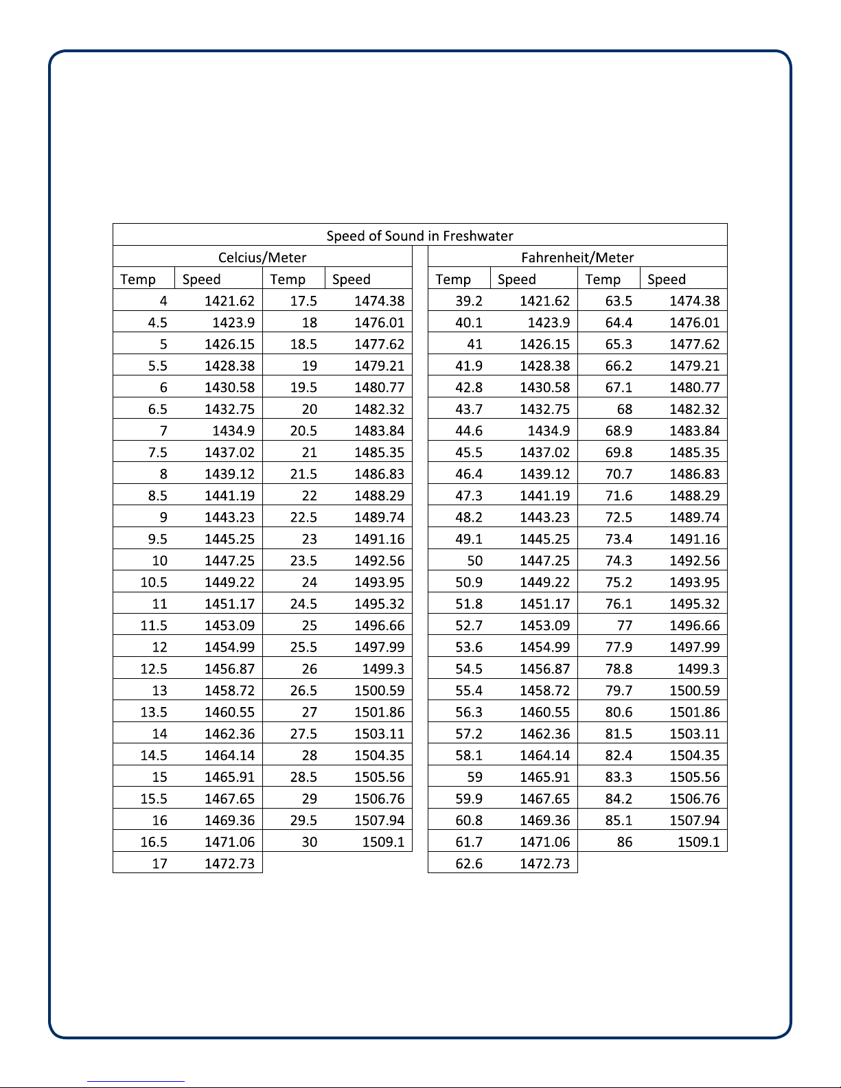
Speed of Sound — Freshwater
Pg 1 of 2
Source: UNESCO equation provided by National Physical Laboratory.
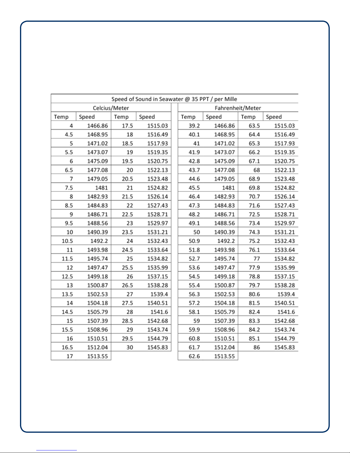
Speed of Sound — Seawater
Pg 2 of 2
Source: UNESCO equation provided by National Physical Laboratory.

Pg 1 of 5
Seafloor
TM
quick start guide
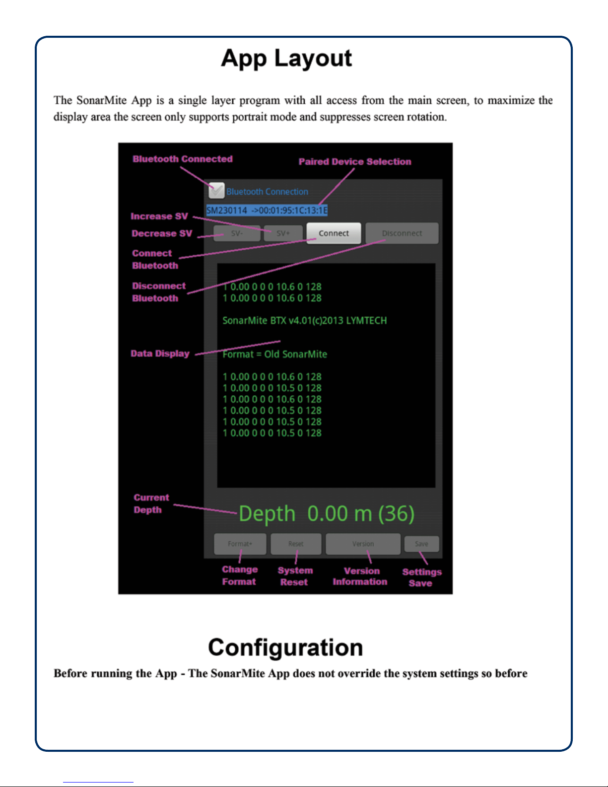
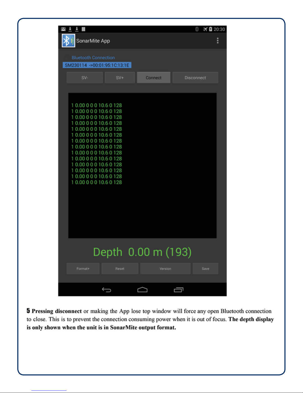
SonarMite Android Bluetooth App
Ver 2.1
Pg 2 of 5
Pg 3 of 5
Pg 4 of 5
Table of contents
Other Seafloor Measuring Instrument manuals


Popular Measuring Instrument manuals by other brands


MALA
MALA CX operating manual

Kobold
Kobold DAG-M1F operating instructions

Dwyer Instruments
Dwyer Instruments DPGA series Specifications-installation and operating instructions

PCB Piezotronics
PCB Piezotronics 352M212 Installation and operating manual

Neutronics
Neutronics ULTIMA ID PRO RI-700H Operation manual

KERN
KERN MLS 50-3...N series Service manual


