Seafloor HyDrone-G2 RCV User manual

HyDrone-G2-
RCV™/ASV™
A quick start guide/user manual.
©Copyright 2016 Seafloor Systems, Inc. All rights reserved.
Page 1
HyDrone-G2-RCV/ASV Quick Start Guide/Manual | Rev 09 Nov. 2017
Seafloor

HyDrone-G2 RCV™ / ASV™
A quick start guide/user manual.
Table of Contents Page No.
1. Introduction .....................................................................................................................................3
2. Equipment Supplied........................................................................................................................3
3. Options for the HyDrone .................................................................................................................3
4. Description of Components
4.1 Exterior...........................................................................................................4
4.2 Access Hatches .............................................................................................5
5. Preparing the Boat for Transport ....................................................................................................5
6. At the job site—BEFORE going into the water
6.1 External assembly..........................................................................................6
6.2 Front Access Hatch........................................................................................6
6.3 Rear Access Hatch ........................................................................................6
6.4 Adding a HydroLite-TM to the frame..............................................................6
6.5 Adding alternative equipment to the frame ....................................................7
7. Arming the Futaba-RCU .................................................................................................................7
7.1 Setting up the boat.........................................................................................7
7.2 Setting up the Futaba RCU............................................................................7
7.3 Futaba RCU Operational Modes....................................................................7
7.4 Final Steps in Preparation..............................................................................7
8.
Conducting the Survey ...................................................................................................................9
9.
Cleaning &Maintenance—AFTER the Survey ............................................................................... 9
10.
Troubleshooting for Commonly Reported Questions..................................................................... 9
10.1 Checking the voltage level of the HyDrone Batteries .................................. 9
10.2 Common Mistake #1 ................................................................................... 9
10.3 Common Mistake #2 ..................................................................................10
10.4 Re-pairing Futaba RCU ..............................................................................10
10.5 Maintaining the Thrusters............................................................................ 10
HyDrone-G2 ASV 10
11.
Connect Hardware ..................................................................................................................................... 11
12.
Arming AutoNav .......................................................................................................................... 11
13.
Launching Mission Planner Application on Laptop ............................................................................12
14.
Setting up Survey/Waypoints (WPs)..................................................................................................13
15.
ConductCompass Calibration. ..........................................................................................................13
16.
Launch Vehicle .................................................................................................................................. 14
17.
Contacting Technical Support............................................................................................................14
HyDrone Schematic
Top View .......................................................................................................................................16
Side, Bottom Views.......................................................................................................................17
Sound Velocity Charts
Fresh Water ..................................................................................................................................18
Sea Water.....................................................................................................................................19
©Copyright 2016 Seafloor Systems, Inc. All rights reserved.
Page 2
HyDrone-G2-RCV/ASV Quick Start Guide/Manual | Rev 09 Nov. 2017
Seafloor

1. Introduction
HyDrone-G2 RCV™ / ASV™
The HyDrone-RCV-G2 is a one-man portable, remotely controlled hydrographic survey catamaran vessel. The
unit works in conjunction with the HydroLite-TM portable echosounder kit to conduct bathymetric surveys in
lakes, ponds, estuaries, rivers and streams. To watch our HyDrone-RCV Video User Manual and
Troubleshooting Guide, go to these links:
https://www.youtube.com/watch?v=hGAuzAUgF34 (User Manual)
https://youtu.be/HOdkXY_Ik7w (Troubleshooting Guide)
2. Equipment Supplied
•HyDrone pontoons (left and right)
•HyDrone mounting frame
•HyDrone 16-volt, 16 Ah battery (2)
•HyDrone battery Charger (2)
•Futaba™ remote controller with neck strap
•Custom rugged shipping case (see Figure 1)
•HyDrone-RCV Quick Start Guide, including
Schematic
Sound Velocity Charts: Freshwater / Seawater
•Hardware:
HyDrone mounting frame bolt
(4) HyDrone Hyfi and bolt (2)
Allen key (1)
Spare inline filte (2)
• 1-year Warranty Parts & Labor
3. Options for the HyDrone-RCV
Figure 1—HyDrone-RCV System in rugged shipping case with user
manual and hardware.
The watertight construction and very stable wide profile offer an ideal stable platform to hold a variety of equipment, i.e.:
•HydroLite-TM singlebeam echosounder
•HydroLite-DFX dual frequency echosounder
•GPS antenna
•Data collector
•Sidescan sonar
•SVP/SVS devices
•Acoustic Doppler current profiler (ADCP)
©Copyright 2016 Seafloor Systems, Inc. All rights reserved.
Page 3
HyDrone-G2-RCV/ASV Quick Start Guide/Manual | Rev 09 Nov. 2017
Seafloor

4.
Description of Components
This section describes the components that make up the HyDrone-RCV. Replacement of broken parts can be
ordered from the online store:
http://seafloorsystems.com/products/parts-accessories/hydrone-parts-accessories
4.1 Exterior
The boat has been designed that when loaded down, it has a very shallow draft. Each vehicle comes with the
following:
4.1.1 ON/OFF waterproof switch to the motor on each pontoon (see Figure 2)
4.1.2 HyDrone mounting frame—the aluminum frame comes with four bolts (see Figure 2)
4.1.3 Removeable Fin (Skeg) on each pontoon
The fins provide additional stability for steering, and as protection for the thrusters. There are
two parts to the fin assembly: a plate (see Figure 3) installed on the bottom of the pontoon, and the fin (see
Figure 4), which slides into the groove of the plate.
Figure 4—Fin with pin to lock
Figure 2—HyDrone mounting frame, two access hatches on each pontoon, and on/off switch
Figure 3—Fin housing and differential
thruster on bottom of pontoon
Figure 5—Differential thruster
4.1.4 Thrusters: Each pontoon comes with a pre-installed brushless differential thruster (see Figure 5).
** IMPORTANT! **
Get it wet! Don’t run the thrusters at high speeds or for extended period out of water to minimize noise and wear.
Rinse. Rinse after use and clean out biofouling and debris occasionally.
©Copyright 2016 Seafloor Systems, Inc. All rights reserved.
Page 4
HyDrone-G2-RCV/ASV Quick Start Guide/Manual | Rev 09 Nov. 2017
Seafloor

Figure 6—Rear access hatch: Futaba RCU 2-channel
receiver, speed controller and internal component for
the ON/OFF switch to the motor
Figure 7—Front access hatch: the battery compartment
includes keyed connectors
4.2 Access Hatches
There are two access hatches on each pontoon:
A. REAR Access Hatch—Speed Controller Compartment: (See Figure 6)
Speed controller—should always be in the ON position (see Figure 6)
Futaba 2-channel receiver: (see Figure 6)
COM2=RIGHT / COM3=LEFT
Receives signals from the Futaba remote control unit (RCU)
Relays the signal along to the speed controller for operation
Tells the boat to give MORE SPEED, SLOW, or STOP
We have pre-programmed other settings, such as voltage cut-off,
FORWARD, REVERSE
B. FRONT Access Hatch—Battery Compartment: (See Figure 7)
The standard boat includes 2x 16-volt, 16 Ah batteries with keyed connectors for
positive and negative connection
5.
Preparing the boat for transport
When transporting the assembled HyDrone, protect the thrusters by keeping them off the ground
and the bed of the vehicle and surround the thrusters with protective material such as foam rubber.
Futaba RCU
The RCU takes four AA batteries; we recommend to keep a supply of extra AA batteries.
Instructions for the RCU are discussed in Section 7.
Transporting the boat
When transporting the assembled Hydrone protect the thrusters by keeping them
off the ground and the bed of the transport vehicle and surrounding them with a
protective material such as foam rubber.
©Copyright 2016 Seafloor Systems, Inc. All rights reserved.
Page 5
HyDrone-G2-RCV/ASV Quick Start Guide/Manual | Rev 09 Nov. 2017
Seafloor

6. At the job site—BEFORE going into the water
Carefully pull the unit out of the transport vehicle and ensure thrusters are not resting on the ground.
Complete the following items:
6.1 EXTERNAL assembly
Attach the crossbar mounting frame
Pull the mounting frame out of the case and attach the frame to each pontoon using
four bolts while in the case to protect the thrusters.
Ensure the following are fastened:
-mounting frame bolts
-fin—ensure safety pin is installed
6.2 FRONT Access Hatch
Ensure Batteries are secure, in position, and fully charged.
6.3 REAR Access Hatch
Ensure speed controller is in ON position.
Note: The speed controller should be in ON position at all times (see Figure 8)
Figure 8—Rear access hatch: ensure speed controller is ON at all times.
6.4 Adding a HydroLite Singlebeam Echosounder to the frame
1. Clip the transom mount to the frame.
2. Attach the GPS antenna on top of pole.
Attach SonarMite echosounder to pole.
Links to HydroLite-TM Quick Start Guide/User Manual
Video—YouTube: https://www.youtube.com/watch?v=SmnCkbmXiGI
PDF Manual: http://seafloorsystems.com/support/software-support
ON/OFF
switch
©Copyright 2016 Seafloor Systems, Inc. All rights reserved.
Page 6
HyDrone-G2-RCV/ASV Quick Start Guide/Manual | Rev 09 Nov. 2017
Seafloor

6.5 Attach additional equipment, as required for the project.
The HyDrone was designed to integrate with the HydroLite-TM singlebeam survey pole kit. As an
alternative, it may accept the following instruments. For more information: info@seafloorsystems.com
•Sidescan sonar
•SVP/SVS devices
•Acoustic Doppler current profiler (ADCP)
7.
7.1
7.2
A
Arming the Futaba RCU
Setting up the boat
Lay the boat into the water.
***IMPORTANT: The joysticks must be in MIDDLE or neutral position prior to next step***
Setting up the Futaba RCU Controls
Turn on the Futaba RCU. Continuous pulsating chimes will be audible, and a warning signal will
appear in the window:
WARN-THR
B Slowly move the LEFT joystick to DOWN position, then back to MIDDLE position. Both the Futaba
RCU, speed controller and boat pontoon receivers/controllers are now armed and ready to operate.
Note: When the system is functioning properly, two chimes will be audible after
positioning the LEFT joystick from MIDDLE to DOWN to MIDDLE position. If continuous pulses of chimes
are heard, please refer to the HyDrone video troubleshooting guide.
7.3 Futaba RCU Operational Modes
UP = Forward
MIDDLE = Neutral
DOWN = Reverse
Also, refer to Section 10—Troubleshooting, for more information on the Futaba RCU.
7.4 Pairing RCU to boat pontoon receivers/ speed controllers
Note: If RCU and receivers were previously paired, the system will automatically pair when
pontoon power switch is turned to the on position. In this case, proceed to step A, seen
below.
A Turn port (left) pontoon power switch to the on position. Wait approximately 15 seconds for
boat receiver to pair with the RCU. Confirm pairing by listening to beeping tones from speed
controller (four fast beeps followed by one long beep). Observe speed controller LED light
flashes red and then extinguishes. Also, observe receiver LED light flashes red, then amber,
then solid green. Perform these steps again to pair starboard (right) pontoon receiver.
B I. On the RCU, press and hold the button marked with a “+”sign. This will bring up the RCU menu.
II. Use the button joystick to highlight “MDL SEL”. Press in the joystick to go to the MDL SEL
©Copyright 2016 Seafloor Systems, Inc. All rights reserved.
Page 7
HyDrone-G2-RCV/ASV Quick Start Guide/Manual | Rev 09 Nov. 2017
Seafloor

menu. Use joystick to highlight “LINK.”
CAUTION: Read all of the following steps before performing any actions:
III. Press in and hold the joystick button to start a 20 second countdown timer. Beeping
tones will be heard as timer counts down, and “RX power OFF!ON”will flash on the
bottom of the menu screen.
IV. Turn on port pontoon power switch before RCU timer completes the countdown.
V. Confirm pairing by listening to beeping tones from speed controller (four fast beeps
followed by one long beep). Observe speed controller light flashes red and then
extinguishes. Also, observe receiver LED light flashes red, then amber, then solid green.
VI. Perform the above steps (2 through 5) to pair starboard pontoon receiver.
C Test controller joysticks. Confirm that port and starboard propellers rotate in proper
directions (forward, neutral and reverse). Ensure propellers rotate at same speed with
joysticks in same position.
Note: If propellers are not working properly, for instance, propellers rotate at different
speeds or continue to rotate with joystick in neutral etc., then perform the following speed
controller calibration.
I. Ensure RCU and receivers are correctly armed and paired. (See previous steps.)
II. Ensure port and starboard pontoon power switches are turned to the off position.
Note: Read all steps below before performing any actions. After pontoon power switch is
turned on, you have approximately three seconds to move the speed controller joystick
from forward position to neutral (middle) position.
Caution: If you hear a string of beeps (musical tones) then immediately turn the pontoon
power switch off. Do not move the pontoon stick until the pontoon power switch is off. Start
procedure over at step 7.4 C II.
III. Move the left speed controller joystick all the way forward.
IV. Turn port pontoon power switch to the on position.
V. After you hear two beeps from the speed controller, quickly and smoothly move the
joystick to the neutral (middle) position.
VI. Confirm correct calibration by listening to beeping tones from speed controller (one long
beep, four fast beeps, one long beep).
Caution: If you hear musical tones, STOP. DO NOT move joystick. Immediately turn
pontoon power switch to off. Start procedure over at step 7.4 II.
VII: After port pontoon is correctly calibrated, then perform calibration procedures for
starboard pontoon.
©Copyright 2016 Seafloor Systems, Inc. All rights reserved.
Page 8
HyDrone-G2-RCV/ASV Quick Start Guide/Manual | Rev 09 Nov. 2017
Seafloor

8. Conducting the survey
Recommended Survey Speed, Battery Endurance, Planning the Survey
1 Push off, remotely drive the boat.
2 Survey speed 2-3 mph (for best data and battery endurance).
3 Batteries will continue for up to 8 hours at the survey speed.
4 Grid formation, one direction, then perpendicular.
9. Cleaning & Maintenance—After the Survey
This section describes how to clean the HyDrone after surveying in FRESH or SALT water.
CAUTION! If turning off the Futaba RCU before the pontoons,
the motors will continue to run and may cause injury!
1 Turn off motors (ON/OFF switches) on each pontoon.
2 Turn off the Futaba RCU.
3 Visually inspect for excessive water inside. If there is water inside the pontoons, you must keep the
boat level when you lift out of the water to prevent damage to the electrical components.
4 Carefully place the boat on the dock, protecting the thrusters by placing over the edge of the dock.
5 If hose is accessible, clean off the outside (ensure hatches are closed).
6 Return all hatches, except for one on each pontoon to allow the system to air dry.
10.
10.1
10.2
Troubleshooting for Commonly Reported Questions
Checking the voltage level of the HyDrone Batteries:
Each battery has a meter and will charge to 16.8 V.
Common Mistake #1: Starting pontoon before turning on Futaba RCU
Please refer to Section 7 Arming the Futaba RCU and please watch these videos: HyDrone
Video User Manual
https://www.youtube.com/watch?v=hGAuzAUgF34
HyDrone Troubleshooting Video Guide:
https://youtu.be/HOdkXY_Ik7w
©Copyright 2016 Seafloor Systems, Inc. All rights reserved.
Page 9
HyDrone-G2-RCV/ASV Quick Start Guide/Manual | Rev 09 Nov. 2017
Seafloor

10.3 Common Mistake #2: Turning on pontoons while joysticks are NOT in MIDDLE
position
Outcome #1: Neutral is not properly set.
Outcome #2: Propellers are not spinning at the same speed.
These outcomes require calibration. Please follow the following instructions
1. Turn OFF both pontoons.
2. Turn OFF Futaba RCU.
3. Joysticks in the MIDDLE position.
4. Turn on Futaba RCU, and make sure it is armed (follow steps in Section 7).
5. Move RIGHT joystick all the way FORWARD.
6. Turn ON the RIGHT poontoon. Two chimes.
7 . Bring RIGHT joystick back to NEUTRAL (middle) position. Three chimes indicates System calibration.
8. If more than three chimes are heard, repeat the process for that pontoon.
9. Turn OFF the RIGHT pontoon
10. Repeat Steps 1 - 9 using the Left pontoon and Left joystick.
These steps are shown in the HyDrone Video Troubleshooting Guide
https://youtu.be/HOdkXY_Ik7w
10.4 Futaba RCU makes more than two chimes after turning it ON
This requires re-pairing with the speed controller
If the Futaba RCU continues to chirp more than two times when turning it on, follow these
instructions to re-pair the RCU with the speed controller:
1. Turn on Futaba RCU and hold it close proximity to the pontoon.
2. Turn on the pontoon that needs to be paired.
3. Locate the speed controller In the REAR access hatch. Press and hold the small black
button labeled “SW” for approximately 3 seconds.
The RED flashing light indicates it is searching to pair with a Futaba RCU.
Note: If the RED light continues to flash, the Futaba RCU may be too far away to pair.
Even 1 foot away may be too far away to pair.
The GREEN solid light indicates it has discovered the Futaba RCU.
10.5 Maintaining the Thrusters
To keep the thrusters working properly, we recommend the following:
1. Don’t run the thrusters at high speeds or for extended periods out of water to minimize over-
heating and wear.
2. Rinse after use in salt water and clean out biofouling and debris occasionally.
©Copyright 2016 Seafloor Systems, Inc. All rights reserved.
Page 10
HyDrone-G2-RCV/ASV Quick Start Guide/Manual | Rev 09 Nov. 2017
Seafloor

HyDrone-G2-ASV™
The HyDrone-ASV is equipped with an AutoNav auto pilot module and the Mission Planner Application that
runs on a base station laptop, connected through a radio telemetry link. It displays the vehicle’s graphical
positioning and progress against a background map of the survey area. Battery voltage, current, and capacity
remaining is monitored via this link.
This Quick Start Guide provides set-up instructions for the AutoNav, Futaba Remote Control System, andthe
Mission Planner Application.
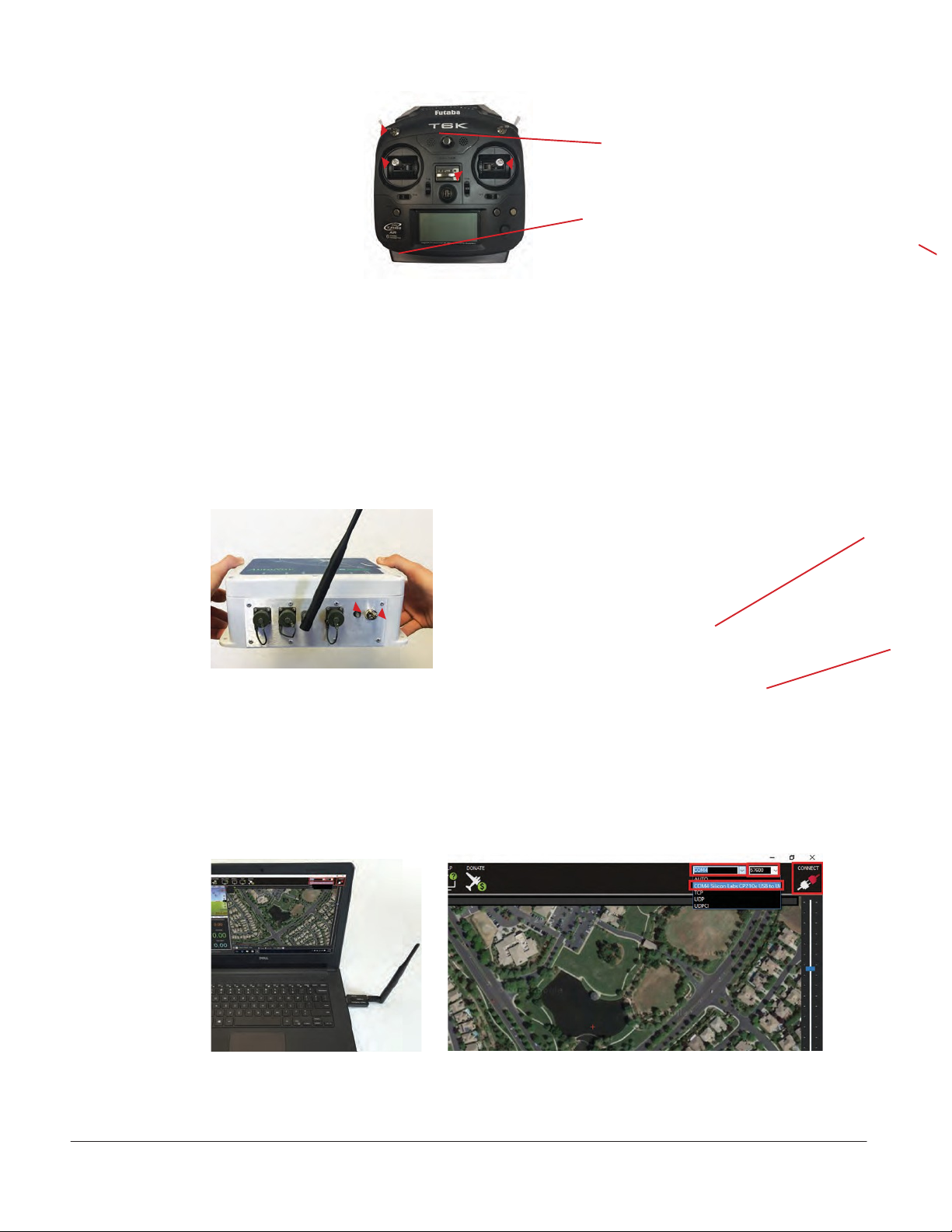
11. Connect Hardware
11.1 Attach the AutoNav unit to the Pontoon frame using supplied hardware—see Figure 1.
11.2 Plug the Port Pontoon cable into the AutoNav Port connector—see Figure 1.
Note: be careful plugging in the male connectors—they are fragile. If the pins get bent and
cross, they will cause a short somewhere in the system).
11.3 Plug the Starboard Pontoon cable into AutoNav Starboard connector—see Figure 2.
11.4 Attach the Radio Telemetry antenna to the AutoNav.
12. Arming AutoNav
12.1 Ensure both Remote Throttle Sticks are in Center position—see Figure 3.
12.2 Ensure Channel 5 switch is in Up position (Manual mode)—see Figure 3.
Starboard
Connectors
Radio
Telemetry
Antenna
Port
Connectors
Figure 1—Attach AutoNav control module to the
Pontoon frame.
Figure 2— Connect the Radio Telemetry antenna
into the AutoNav port. Plug the Port and Starboard
pontoon cables into the AutoNav port connectors.
12.3 Turn Remote unit to On position (it will beep rapidly)—see Figure 3.
12.4 Move Left Throttle fully Down position.
12.5 Return Left Throttle to Center position (beeping will stop).
12.6 Turn AutoNav system switch to DOWN position—see Figure 4.
Note: Start-up tune will play, followed by three beeps. Turn on both pontoon switches.
©Copyright 2016 Seafloor Systems, Inc. All rights reserved.
Page 11
HyDrone-G2-RCV/ASV Quick Start Guide/Manual | Rev 09 Nov. 2017
Seafloor
Channel 5 Switch
Up = Manual
Down = Autonomous
Left Throttle Stick
Before turning on the Remote
unit, both Throttle Sticks
should be in center position.
Right Throttle Stick
Before turning on the Remote
unit, both Throttle Sticks
should be in center position.
On Switch
Figure 3: Operation features of the Remote
Control unit with the AutoNav.
12.7Press and hold ARM button (red flashin LED) for three seconds.
Note: LED will turn solid red; props are now ARMED.
12.8 Channel 5 toggle UP is Manual mode;
Channel 5 toggle Down is Autonomous mode.
13. Launching Mission Planner Application on Laptop
Red LED
ON / OFF Switch
Figure 4: AutoNav On switch on front panel of AutoNav.
Red solid and flashin LED on front panel.
13.1 Plug in USB Radio Telemetry—see Figure 5.
13.2 Launch Mission Planner application from desktop shortcut of laptop.
13.3 Select COM port (top right corner of the screen)—see Figure 6.
13.4 Set Baud Rate to 57600—see Figure 6.
13.5 Click on Connect tool—see Figure 6.
Figure 5: Attach USB Radio
Telemetry to the
Mission Planner
Laptop.
Figure 6: Select COM port in Mission Planner application and
select baud rate.
©Copyright 2016 Seafloor Systems, Inc. All rights reserved.
Page 12
HyDrone-G2-RCV/ASV Quick Start Guide/Manual | Rev 09 Nov. 2017
Seafloor
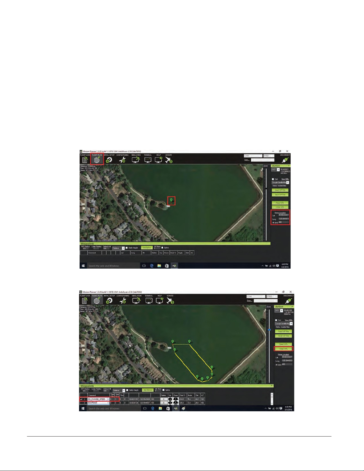
14. Setting up Survey/Waypoints (WPs)
A Locate survey area on map.
B Zoom in on survey area.
C Click on Flight Plan tool (upper left of tool bar)—see Figure 7.
D Click Home Location button to set Home (right side of screen)—see Figure 7.
E Click on map to add Waypoints—see Figure 8.
F Click on Write WPs to upload to AutoNav (right side of screen)—see Figure 8.
15. Conduct Compass Calibration
Calibrate compass each time each time the survey location has been changed.
Figure 7: Click on Flight Plan tool (upper left of tool bar);
Click on Home Location to set Home (right side of screen).
Figure 8: Add Waypoints by clicking on the map.
©Copyright 2016 Seafloor Systems, Inc. All rights reserved.
Page 13
HyDrone-G2-RCV/ASV Quick Start Guide/Manual | Rev 09 Nov. 2017
Seafloor
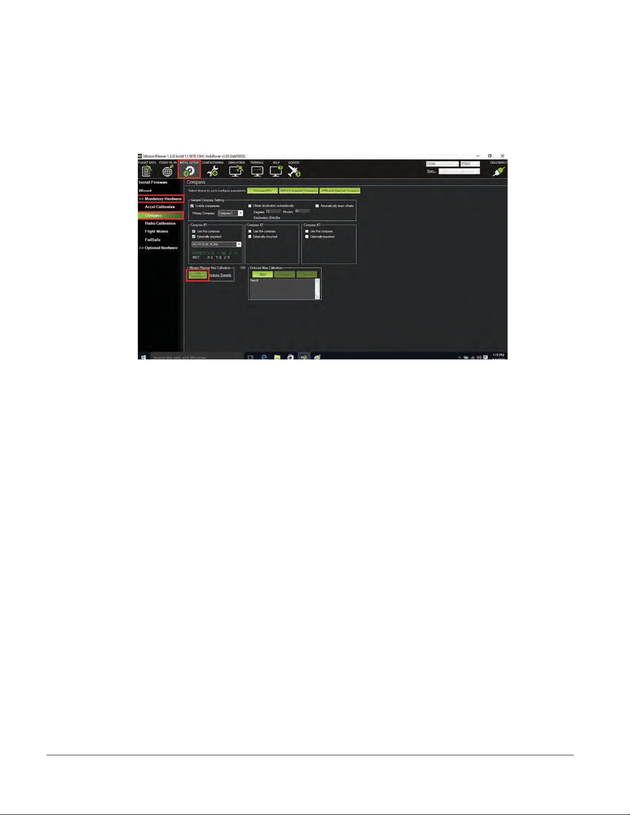
15.1 Click on Initial Set-up tool (top left)—see Figure 9.
15.2 Click on Mandatory Hardware—see Figure 9.
15.3 Click on Compass—see Figure 9.
15.4 Start Live Calibration under Mission Planner Mag Calibration—see Figure 9.
Figure 9: Click on Initial Set-up tool.
Click on Mandatory Hardware.
Click on Compass.
Start Live Calibration under Mission Planner Mag Calibration.
15.5Manually rotate the AutoNav unit slowly around all axis, per instructions on
screen.
Note: this needs to be done outdoors.
15.6: When Calibration is completed, the program will beep as notification Click OK to
save the new parameters.
16. Launch Vehicle
16.1 Place vehicle in water, clear of obstacles.
16.2 Manually move boat toward the waypoint.
16.3 Move Channel 5 switch Down to Auto mode; vehicle will now follow the survey route.
16.4 On laptop, switch to Flight Data Screen to view vehicle status.
Note: When vehicle transits to last waypoint, it will stop.
16.5 Switch Channel 5 to Manual mode (UP position) to control return of vehicle.
17. Contacting Technical Support:
Phone: (530) 677-1019
Email: info@seafloorsystems.co
Hours: Monday - Friday, 8:30 a.m. - 5:00 p.m. Pacific Time
©Copyright 2016 Seafloor Systems, Inc. All rights reserved.
Page 14
HyDrone-G2-RCV/ASV Quick Start Guide/Manual | Rev 09 Nov. 2017
Seafloor

This is a typical set-up for the HyDrone-ASV-G2, with hydrolite-TM echosounder.
Seafloor Systems, Incorporate
4415 Commodity Way, Shingle Springs, CA 95682 ·USA
(530) 677–1019 | [email protected] | ww .seafloorsystems.co
©Copyright 2016 Seafloor Systems, Inc. All rights reserved.
Page 15
HyDrone-G2-RCV/ASV Quick Start Guide/Manual | Rev 09 Nov. 2017
Seafloor

HyDrone-G2-RCV™ Schematic
(Top View)
©Copyright 2016 Seafloor Systems, Inc. All rights reserved.
Page 16
HyDrone-G2-RCV/ASV Quick Start Guide/Manual | Rev 09 Nov. 2017
Seafloor

HyDrone-G2-RCV™ Schematic
(Bottom/Side Views)
©Copyright 2016 Seafloor Systems, Inc. All rights reserved.
Page 17
HyDrone-G2-RCV/ASV Quick Start Guide/Manual | Rev 09 Nov. 2017
Seafloor

Speed of Sound — Freshwater
Source: UNESCO equation provided by National Physical Laboratory.
©Copyright 2016 Seafloor Systems, Inc. All rights reserved.
Page 18
HyDrone-G2-RCV/ASV Quick Start Guide/Manual | Rev 09 Nov. 2017
Seafloor

Speed of Sound — Seawater
Source: UNESCO equation provided by National Physical Laboratory.
©Copyright 2016 Seafloor Systems, Inc. All rights reserved.
Page 19
HyDrone-G2-RCV/ASV Quick Start Guide/Manual | Rev 09 Nov. 2017
Seafloor

Seafloor Systems, Incorporate
4415 Commodity Way, Shingle Springs, CA 95682 ·USA
(530) 677–1019 | [email protected] | www.seafloorsystems.com
©Copyright 2016 Seafloor Systems, Inc. All rights reserved.
Page 20
HyDrone-G2-RCV/ASV Quick Start Guide/Manual | Rev 09 Nov. 2017
Seafloor
This manual suits for next models
1
Table of contents
Other Seafloor Measuring Instrument manuals


Popular Measuring Instrument manuals by other brands

JEAN MÜLLER
JEAN MÜLLER PLNovameter 2000 Users’s Manual and Instructions for Installation

Cadex
Cadex BatteryStore C5100B user guide

Mitutoyo
Mitutoyo 700 Series user manual

Lutron Electronics
Lutron Electronics SP-82AM manual

Vermason
Vermason 222660 Operation and maintenance manual

Keithley
Keithley 6514 quick guide


