Resonance Spin Mate User manual

NMR Analyzer “Spin Mate”
Operation manual
RESONANCE
SYSTEMS

2
Content
1. General safety information ................................................................................................................... 3
2. Spin Mate Overview .............................................................................................................................. 5
2.1. NMR Analyzer components................................................................................................................ 5
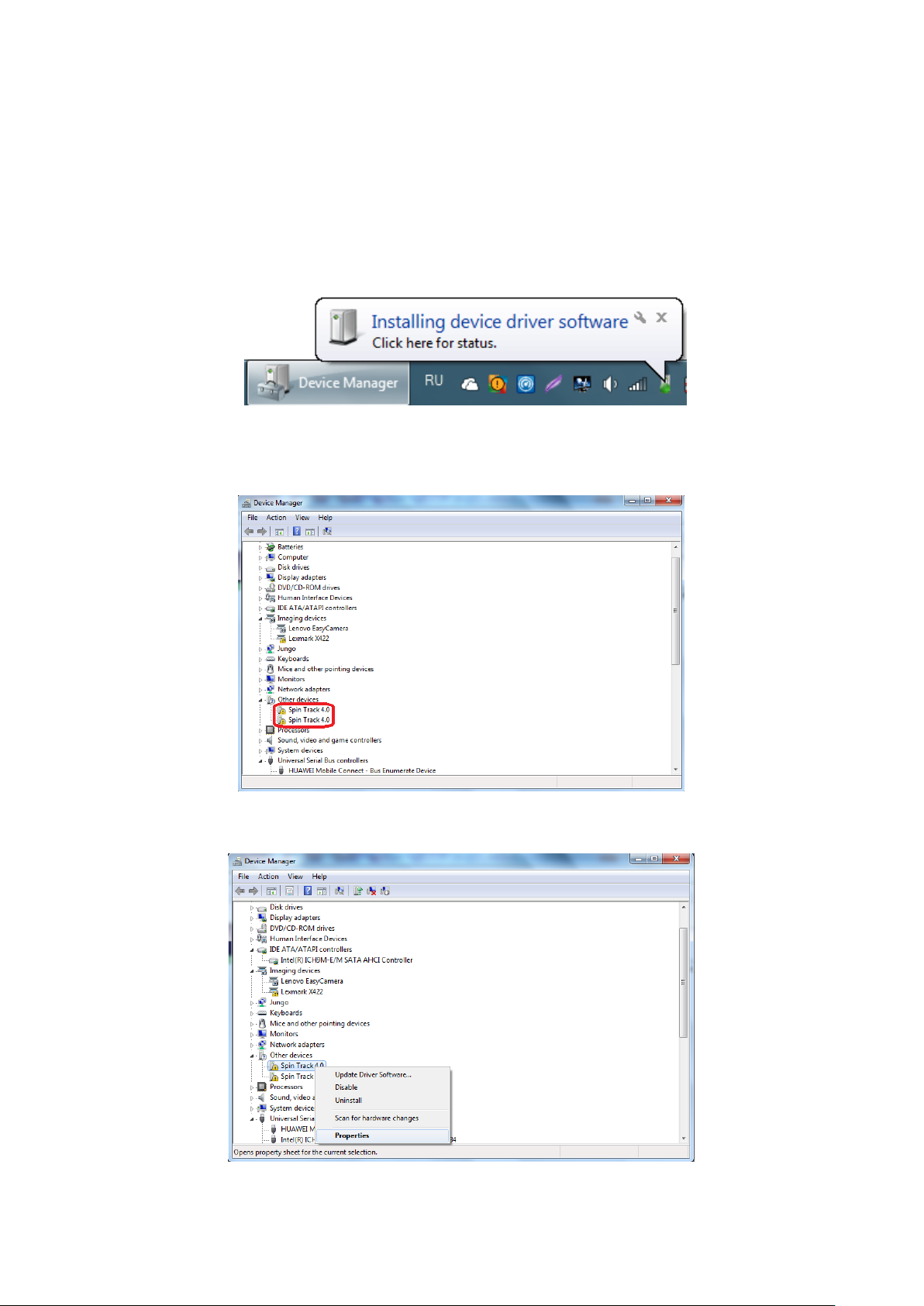
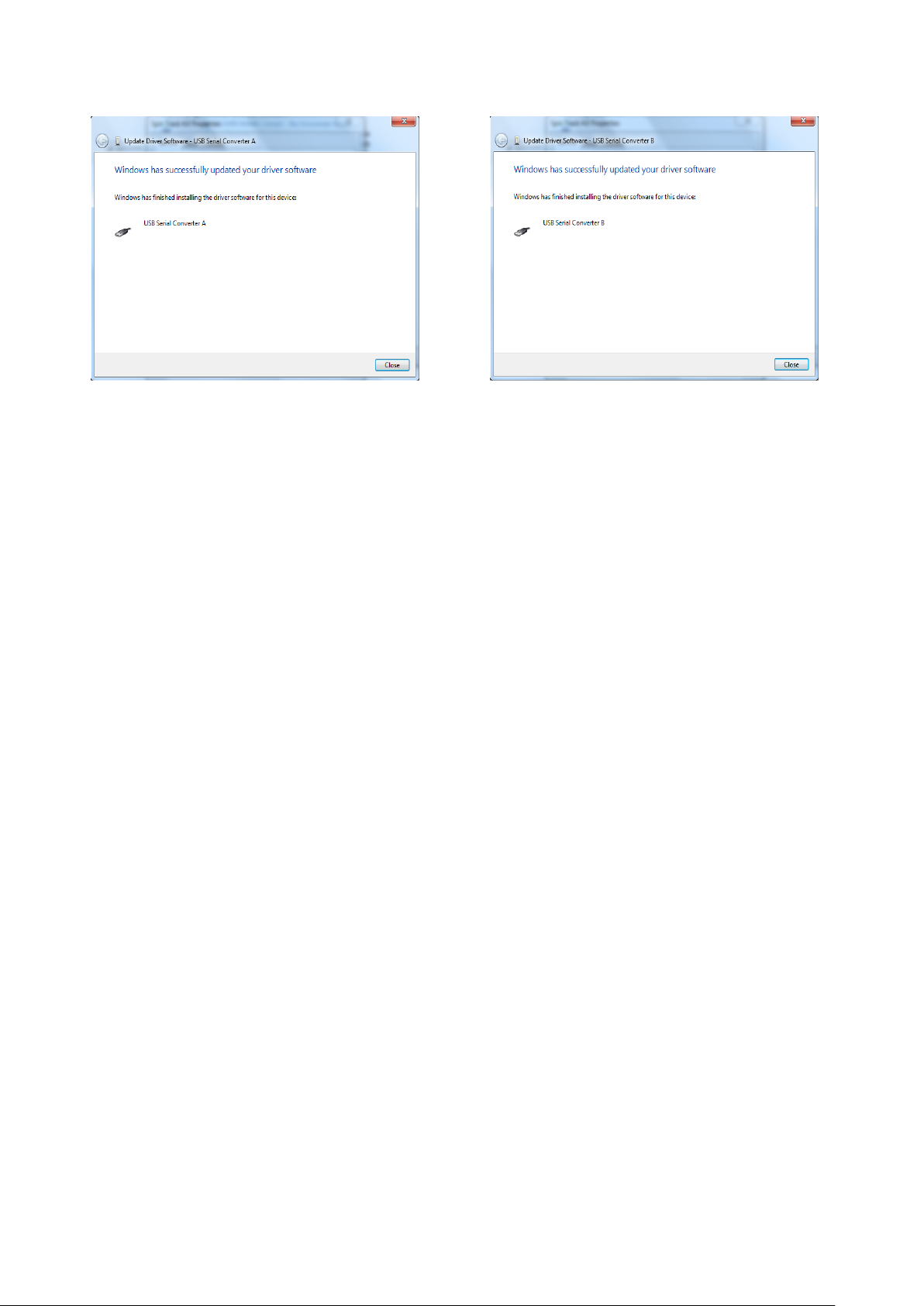
2.2. Connecting Hardware to PC and Drivers Installation......................................................................... 8
2.3. Technical Characteristics and Service Conditions ............................................................................ 11
2.4. Preparation of Spin Mate for measurements................................................................................... 12
3. Software Overview .............................................................................................................................. 13
3.1. Software Installation ................................................................................................................... 13
3.2. Menu and Control Board............................................................................................................. 16
3.3. Measuring System Settings ......................................................................................................... 23
4. Software Start-up ................................................................................................................................ 31
4.1. Preparation of Validation Sample................................................................................................ 31
4.2. First Start-up and Daily Check ..................................................................................................... 31
4.3. Applications Test ......................................................................................................................... 37
5. Relaxation Time Measurements.......................................................................................................... 39
5.1. Spin-lattice Relaxation Time T1.................................................................................................... 39
5.1.1. Inversion-Recovery experiment .............................................................................................. 39
5.1.2. Saturation-Recovery experiment ............................................................................................ 39
5.1.3. Utilizing applications for measuring Spin-lattice Relaxation Time.......................................... 40
5.2. Spin-spin Relaxation Time T2....................................................................................................... 44
5.2.1. Free Induction Decay (FID) ...................................................................................................... 44
5.2.2. Solid Echo (SE) ......................................................................................................................... 44
5.2.3. Magic Sandwich Echo (MSE).................................................................................................... 45
5.2.4. Utilizing applications for measuring Spin-spin Relaxation Time ............................................. 46
5.2.5. Hahn Echo (HE). Main information and applying.................................................................... 46
5.2.6. Carr-Purcell-Meiboom-Gill (CPMG). Main information and applying ..................................... 48
6. Diffusion Measurements ..................................................................................................................... 51
6.1. Calibrating of Gradient Multiplier ............................................................................................... 52
6.2. Measurements of Self-Diffusion Coefficients.............................................................................. 54
7. Spectrum Construction.................................................................................................................... 56
8. Development Applications for Software Relax8.............................................................................. 58
8.1. Syntax of Inline Programming Language of Relax8 ..................................................................... 58
8.2. Comments to Examples of Applications...................................................................................... 69

3
1. General safety information
The chapter describes the general safety precautions and precautionary measures that must
be observed when operating the TD-NMR analyzer (Spin Mate). The instructions are intended to
supplement, but not replace, the normal safety regulations in your region. The information provided
does not cover all safety precautions that must be observed in a laboratory. Ultimately, the
responsibility for a well-maintained and safe laboratory environment rests with the user and his
organization.
DANGER:
For the safety of the user, all safety instructions and safety information must be taken into account
and strictly followed. Therefore, these operating instructions must be available to all users at all
times. Read all manuals supplied with the Spin Mate system (including manuals available online)
before setting up and operating the system. Read the safety instructions in this chapter and those
in the other manuals with particular care. When assembling, commissioning the SpinMate system
and performing analyzes, strictly adhere to the specifications in the manuals and the Relax8
operating software.
1.1 Important precautions
The Spin Mate system was developed in accordance with a large number of international
standards, which are decisive for the safety of laboratory equipment. Routine use is not dangerous.
With simple and sensible precautionary measures, you can ensure the safe operation of your system
in the long term.
• Make sure that the system is placed securely and stably on a sufficiently stable surface (e.g.
table with a load capacity of 100 kg/m2).
• Do not place the Spin Mate system near any heat sources, such as radiators.
• Do not block the ventilation openings on the sides, top or bottom of the housing.
• Do not cover the top of the cases
• Make sure that all devices are properly connected to the mains, i.e. connect the devices to a
power supply that has either a switch or some other device for interrupting the power supply.
• Only plug the power cord into sockets that have a grounded protective conductor connection
• In particular, make sure that all devices are securely grounded.
• Do not open any housings. They serve to protect against strong magnetic fields and electrical
hazards. There are no user-serviceable components. Otherwise there is a risk of strong magnetic
fields (e.g. influence on pacemakers) and mechanical injuries.
• Keep the system dry, especially the magnet and the sample volume.
• Do not use flammable gases to purge the device. Use dry, oil-free nitrogen or air to purge the
device.
• Only operate the spectrometer system indoors under the following conditions:

4
- Ambient temperature range: 293±5 K (from 15 to 25 °C);
- Relative humidity 90% maximum (non-condensing)
1.2. Requirements for the user
The systems may only be set up and used by laboratory personnel and persons who, due to
their training and professional experience, are familiar with the possible dangers that can arise
during operation. Personnel without relevant training or persons who are in training require careful
supervision by a qualified person.
1.3. Location and ventilation
Do not place the spectrometer in a poorly ventilated area of the laboratory when using
nitrogen as the purge gas.
1.4. Risk of fire and explosion
The Spin Mate system with heating and its contact with flammable vapors can trigger an
explosion. Therefore, flammable solvents and samples should not be kept near the system. During
sample preparation, such materials must be handled in a safe area away from the system, such as
in a fume hood.
1.5. Improper use
Any use other than those mentioned and any application that does not correspond to the
technical data is deemed to be improper use. Improper use can result in dangerous situations for
operators and / or devices and damage to property. The user bears the sole risk for any damage or
dangers that can be attributed to improper use. In particular, the following applications are not
permitted:
Carrying out repair and maintenance work that is not explained in these operating
instructions by the user.
Opening houses / cases, dismantel moduls, components, subsystems.
If the Spin Mate system is used in a manner not described by the manufacturer, the safe
functioning of the system may be impaired. No modifications of any kind may be made to the system
without prior consultation with the manufacturer and without written approval. Modifications and
upgrades may only be carried out by service technicians authorized by Resonance Systems. The
manufacturer rejects claims for damages based on unapproved modifications without exception. If
the system is operated in a way that is not specified here, its safety may be impaired and the user
may be endangered.

5
2. Spin Mate Overview
2.1. NMR Analyzer components
Compact TD-NMR analyzer Spin Mate is an ideal instrument for such applications as Relaxation
times measurement, Surface Area and Wettability of nanoparticles and colloidal systems,
Crystallinity and Domain Sizes in Polymers and many others. Observable nuclei: 1H (basic
configuration).
Pic. 2.1. Spin Mate.
Front and back panels of Spin Mate are shown schematically in Pic. 2.2-2.3.

6
Pic. 2.2. Front panel of Spin Mate.
POWER –power LED. Switched to 100 % of brightness if temperature of magnet stable,
otherwise flashes at 50 % of brightness;
MAGNET –indicates magnet heating;
MEASUREMENT –indicates active measurement process;
1–OLED display. It shows set up temperature of the magnet, actual magnet temperature,
temperature of air inside the system and current consuming power (in %%);
2–sensitive power button. This button switches on the power analog part of NMR analyser.
In standby mode its brightness and brightness of OLED display is 50 % and 100 % when the
analyser is fully switched on. Caution –measurement is not possible if this button is
switched off.
1
2

7
Pic. 2.3. Back panel of Spin Mate.
AC Input –power input with integrated switcher. This switcher switches on digital part of
the analyser and magnet heater. The temperature is stored in the internal memory and the
factory preset is +35 °C;
USB –USB connector.

8
2.2. Connecting Hardware to PC and Drivers Installation
2.2.1. The power switches on back panel units must be in position “O” – turned off.
2.2.2. Connect the Spin Mate to the PC by USB cable through USB port.
2.2.3. Connect the power supply cables to the Spin Mate.
2.2.4. Turn on the PC. Turn on the power of NMR Analyzer by pressing the power switch on the
back panel of the analyzer to the position “I”.
2.2.5. The “Installing device driver software” MS Windows 7 message will appear (Pic. 2.5).
Pic. 2.5. MS Windows message.
2.2.6. For the drivers installation you should open Device Manager. In the next window you will
see the following –see Pic. 2.6.
Pic. 2.6. Device Manager window.
2.2.7. The right click on Spin Mate 4.0 and choose Properties (Pic. 2.7).
Pic. 2.7. Drivers installation.

9
2.2.8. The Spin Mate 4.0 Properties window will appear (Pic. 2.8), in which you should push on
Update Driver button.
Pic. 2.8. Spin Mate 4.0 Properties window.
2.2.9. The Update Driver Software –Spin Mate 4.0 window will appear (Pic. 2.9), in which you
should click on Browse my computer for driver software.
Pic. 2.9. Update Driver Software –Spin Mate 4.0 window.
2.2.10. Choose the Drivers folder where Relax8 was installed by the Browse... button as it is
shown at the Pic. 2.10. Click on Next.
Pic. 2.10. Search of the appropriate drivers.

10
2.2.11. The result of drivers installation is shown in Pic. 2.11 a and b.
a
b
Pic. 2.11. Result of installation drivers.
2.2.12. Push on Close button.

11
2.3. Technical Characteristics and Service Conditions
The main characteristics of the console and magnet system of NMR Analyzer Spin Mate and
the PC requirements are presented in tables 2.1 and 2.3.
Table 2.1. Basic characteristics of the NMR Analyzer Spin Mate.
Hardware
1H Frequency: 18 MHz
PC connection: High Speed USB 2.0
Total gain: 90 dB
Noise figure: < 1.5 dB
Ringing time for complete system: < 8 μs
Maximal 90-degree pulse duration: 3 μs
Power requirements
100..240 VAC, 50..60 Hz
Relax8 software
Pulse sequence: Fully programmable cycles, events,
durations, phase shifts
Supported OS: Windows 7, 8, 10
Data compatibility: ANSI Values Columns, Microsoft Excel®
Dimensions
300x174x172 mm
Weight
16 kg
Power consumption
Max. 100 W
Tube diameter
5 or 10 mm on demand
Table 2.2. PC requirements.
Category
Minimum
Recommended
Operating system
Windows 7, 8, 10
RAM, Gb
4
8
Processor
Intel® Core™ i3-4000M
Intel® Core™ i5-6200U
Monitor resolution
1600x900x16bpp
1920x1200x16bpp

12
2.4. Preparation of Spin Mate for measurements
2.4.1. Set the POWER switch on the back panel to the “O” position. Connect the NMR analyzer to
the AC network.
2.4.2. Turn on the switcher the back panel to the “I” position, OLED display on the front panel and
power button on the front panel should light up at 50% of brightness. Check the indication
of the display –it has to show information according paragraph 2.1.
2.4.3. Maintain the NMR analyzer in the ON state for 2 hours to enter the operating mode.
2.4.4. The power LED flashes if actual temperature does not reach the set value. If does, this LED
bright permanently. Internal speaker sounds every time when actual temperature comes
inside or outside the acceptable temperature range.
2.4.5. Touch the sensitive power button on the front panel. The brightness of the button and OLED
display switches to 100 %.
2.4.6. Set up the tube with a sample to the sensor probe head.
2.4.7. Turn on the PC. Download and run the Relax8 software.

13
3. Software Overview
Software Relax8 is the powerful tool both to use the standard NMR relaxation routines and to
create new applications. The built-in script language based on widespread Pascal syntax is enriched
with commands of fitting, Fourier and Laplace transforms, Low-pass filtering. The script supports
dialogue windows, static messages, user-defined diagrams, data manipulation procedures.
3.1. Software Installation
3.1.1. Insert the installation CD in CD-drive / Open folder with the software.
3.1.2. Run the Setup.exe file to start the installation and follow the instructions. Choose the
language of the installation program (Pic. 3.1).
Pic. 3.1. Setup language selection.
3.1.3. The Welcome window will appear (Pic. 3.2). Press the Next button.
Pic. 3.2. Setup Welcome window.
3.1.4. Choose the destination folder for software location by the button Browse… (Pic. 3.3).
Press Next button for further step.

14
Pic. 3.3. Selection of the program destination.
3.1.5. Choose the Start Menu folder where the program’s shortcut should be located by the
button Browse… (Pic. 3.4). After this procedure press the Next button.
Pic. 3.4. Choice of the Start Menu folder for Relax8 shortcut creation.
3.1.6. To continue the program installation click the Install button or press Back to return to
the previous steps for any settings changing (Pic. 3.5).

15
Pic. 3.5. Readiness to installation.
3.1.7. The software installation is complete. Press the Finish button to exit Setup (Pic. 3.6).
Pic. 3.6. Finishing of Relax8 installation.

16
3.2. Menu and Control Board
The Relax8 software has the opportunity to represent the data graphs and so to save the data
to the file. There are also several methods for convenient control of the measurement process. To
provide easy access for the measurement and the experiment observation the screen is divided into
following parts (Pic. 3.7):
System Menu Bar
Main Menu Bar
Measurement Tool Bar (Functional Buttons and Built-in Applications, Stop/Start Button)
Standard Windows (Application Windows, Log Window)
Experiment Status Bar
Mode Switcher
Command Line Mode
Pic. 3.7. Software Interface.
3.2.1. System Menu Bar
System Menu Bar allows minimizing, displaying or closing the program.
3.2.2. Main Menu Bar
Main Menu contains the set of menus at the top of screen. The menus allow the user to control
the measurement process. The Main Menu Bar consists of the following sections: File, Experiment,
Application, Data Base, Help and Support, Tune Frequency, Setups.
• File
• Experiment
• Application

17
• Data Base
• Help and Support
• Tune Frequency
The basic commands of the Main Menu Bar and corresponding keyboard shortcut
combinations are shown in the Table 3.1.
Table 3.1. The basic commands of the Main Menu Bar.
File
Load Application
The opening of the standard or created earlier application
with *.app extension
F3
Save Application
The saving of the new or changed application with *.app
extension
F2
New Application
It is inactive
Exit
The closing of the Relax8
Alt + F4
Experiment
Run
The starting of the experiment corresponding to the active
application
F9
Stop
The stop of the experiment
F8
Setups
The showing of the information about the system and the
experiment parameters
F5
Application
Sample Info
User can set the sample description (name, comments,
mass etc.)
App Panel
User can change the default folder for saved data

18
Simple Interface
It is inactive
Data Base
Data Base
Adds new record to results database and gives the access
to its content
Add Record
Help and Support
Help and Support
It is inactive
Instrument Info
Get serial number of the device
Firmware Update
Loads new firmware
About Resonance
Systems
It is inactive
Tune Frequency
Tune Frequency
Starting the procedure of fine resonance setting
Ctrl+R
Setups
Setups
The showing of the information about the system and the
experiment parameters
F5
3.2.3. Functional Buttons
The Measurement Tool Bar is the panel for convenient and quick experiment handling. It is
positioned at the top left of program screen and includes the set of Functional Buttons. The
Measurement Tool Bar allows the user to perform the most often exploitable tasks by left clicking
on an icon. There are 5 functional buttons: Load Application and Settings (F3), Save
Application and Settings (F2), Tune Resonance (Ctrl+R), Setups (F5), Sample Info
Panel (Pic. 3.8).
Рiс. 3.8. Functional buttons.
3.2.4. Experiment Status Bar
The Experiment Status Bar (Pic. 3.9), which is situated at the bottom right of screen, is
represented progress of experiment in the real-time mode.
Pic. 3.9. Experiment Status Bar.
3.2.5. Stop/Start Button
Button for running experiment from active application window is located at the bottom left
part of screen (Pic. 3.10 a). During accomplishment of experiment this button is in use as a button
for stopping the being performed application (Pic. 3.10 b).

19
a b
Рiс. 3.10. Start/Stop application button.
3.2.6. Application Window
The Application Window appears after standard application loading for further measurement
performing if Load Application and Settings button from Functional Buttons field was pressed
and selected application (Pic. 3.7). The applications are written using the Pulse Programming
Language, which is similar to Pascal. Applications should be saved to a file with the extension *.app
using the command Save Application from the pull-down menu File or by using appropriate icon on
the Functional buttons bar. The Application Window is depicted in Pic. 3.7.
3.2.7. NMR Signal Window
3.2.7.1. NMR Signal
The measuring NMR signal can be observed in the Signal Window (Pic. 3.7, Pic. 3.11) in the
real-time mode. The Signal Window has three sheets: screen of NMR Signal, XY Plot with area for
plotting of spectrum or of graphs and Excel.
Pic. 3.11. NMR Signal Window.
Window of NMR signal allows observing amplitude of signal (Magn –magnitude) and also the
in-phase (Im –imaginary) and quadrature (Re –real) parts of signal. Also one can watch every single
signal or accumulating (Acc) signal. The NMR Signal Window has the option of automatic scale of
signal to the window dimensions (Auto scale), the possibility to hide and show the lines (Lines) and
the points (Points) of magnitude on the graph. These options could be hidden or shown by double-
clicking on the Signal Window region. At the X-axis the time in microseconds is displayed, and the
Y-axis shows the NMR signal amplitude in arbitrary units.
Displaying of the NMR signal can be scaled on the Y-axis by using the scroll of the PC-mouse.
To represent certain part of signal in whole window one should select required region by using the
left button of the PC-mouse. To return in previous conditions of Y-scaling and by default X-scaling
one should select some region to direction from the right to the left by using the left button of the

20
PC-mouse. Moving NMR signal field of view could be done by moving PC-mouse with pressed the
right button of it.
Coordinates of position PC-mouse pointer in the NMR Signal Window are displayed in the
Status Bar (Pic. 3.7).
Experimental data displayed in the Signal Window can be saved to a file with the extension
*.dat or to a graphic file using the command Save Signal as Picture by pressing the right button of
the PC-mouse at the Signal Window.
3.2.7.2. XY Plot
Data obtained can be plotted into this window (Pic. 3.12) owing to procedures in application
window (code of pulse sequences). For this purpose following procedures are applied.
Pic. 3.12. XY Plot tab.
Menu of XY Plot tab contains File, View, Data and Analysis (Pic. 3.13).
Pic. 3.13. Menu of XY Plot tab.
Table 3.2. Description of menu sections.
Tab
Sections
File
Open
Opening a file with results
Save
Saving a file with results
View
Log X
X-axis into a logarithmic scale
Log Y
Y-axis into a logarithmic scale
Clear Experimental
Resetting experimental points
Clear Fit Curve
Resetting a fitting curve
Data
Edit Table
Editing XY data
Get ADC Magn
Getting magnitudes from ADC
Update Moved
Points
Updating coordinates of moved
points
Export Wizard
Advanced settings for data and
pictures
Table of contents
Other Resonance Measuring Instrument manuals

Resonance
Resonance r15c Owner's manual

Resonance
Resonance VM200 User manual

Resonance
Resonance r25c Instruction Manual

Resonance
Resonance r17a Owner's manual

Resonance
Resonance r07a Instruction Manual

Resonance
Resonance R37A Owner's manual

Resonance
Resonance R140 Instruction Manual

Resonance
Resonance R26M Instruction Manual