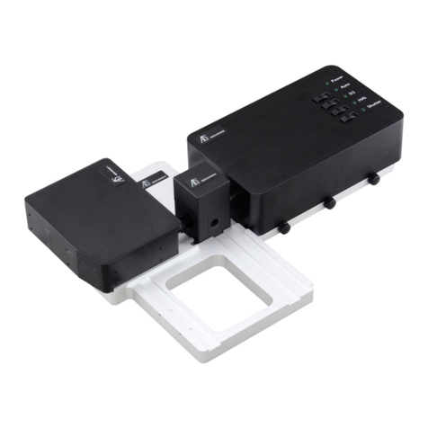
Figure2.1
.
Figure
2.2 .
Figure 2.3
.
Figure2.4
.
Figure2.5
.
Figure2.6
.
Figure 3.1
.
Figure3.2
.
Figure 3.3
.
Figure3.4
.
Figure 3.5
.
Figure3.6
.
Figure 3.7
.
Figure3.8
.
Figure
3.9
.
Module Nameplate
....................................................................................
2-3
Front Panel of the IQ Power Meter Series modules
.......................................
2-4
Typical Main Window
......................................................................................
2-8
NormalModeMonitor W~ndow
.....................................................................
2-9
CalibrationMode Monitor Window
..................................................................
2-9
StabilizingIcon
.........................................................................................
2-10
Main Window
-
Normal Mode
..........................................................................
3-2
ChannelSetup Window (IQ-1100 and IQ-1500)
.............................................
3-8
ChannelSetup Window (IQ-1200)
..................................................................
3-8
Definingthe Virtual Channel
.........................................................................
3-11
Units List Box
................................................................................................
3-14
ResolutionList Box
.................................................................................
3-15
Sampling Rate List Box
.............................................................................
3-16
..............................................................................................
Offset Edit Box 3-17
................................................................
Adding and Deleting Wavelengths 3-17
~igure4.1
.
Figure4.2
.
Figure4.3
.
Figure4.4
.
Figure4.5
.
Figure4.6
.
Figure4.7
.
Figure4.8
.
Figure4.9
.
Figure3-10
.
Setting Wavelength
.......................................................................................
3-1
9
-
Figure3-11
.
Absolute Power Display
...............................................................................
3-20
Figure3-12
.
RelativeDisplay Mode
..................................................................................
3-21
Figure3-13
.
Acquisition Setup Window (IQ-1100 and IQ-1500)
.......................................
3-25
Figure3-14
.
AcquisitionSetup Window (IQ-1200)
............................................................
3-26
Figure3-15
.
Main Window in NormalModeduring Data Acquisition
................................
3-28
Figure3-1
6
.
Trigger Condition Box
...................................................................................
3-30
Figure3-17
.
Data Displayed by Text Editor
......................................................................
3-33
Fi~ure3-18
.
Data into
a
Spreadsheet Program
................................................................
3-34
Graphical Displav Mode Window
...................................................................
4-1
.
.
Two Curves inthe Graphical DisplayArea
.....................................................
4-4
Three Channel Resultsinthe Graphical Display Area
....................................
4-5
..............................................................................................
Options Window 4-7
Channel Selectionfor Real-Time Sampling
...................................................
4-9
Refresh Rate Window
...................................................................................
4-12
Zoom Control Buttons
...................................................................................
4-13
........................................................................................................
Scrolling 4-14
MarkerControl Display
.................................................................................
4-16
.
Figure
4-1
0
.
Print View Window
....................................................................................
4-18
Figure5-1
.
Main Window
.
CalibrationMode
................................................................
5-2
-
Figure
5.2
.
Step-by-step Procedure(Setup)
.................................................................
5-7


