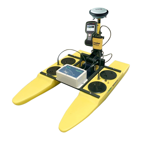
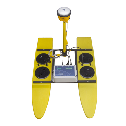
Seafloor EchoBoat-G2-RCV User manual

Page 1
EchoBoat-G2-RCV Quick Guide/User Manual Rev 2 AUG 2017
© Copyright 2017 Seafloor Systems, Inc. All rights reserved.
!
!
EchoBoat-G2-
RCV / ASV™
A quick start guide/user manual.

Page 2
EchoBoat-G2-RCV Quick Guide/User Manual Rev 2 AUG 2017
© Copyright 2017 Seafloor Systems, Inc. All rights reserved.
!
!
EchoBoat-G2-RCV / ASV™
A quick start guide/user manual.
Table of Contents Page
1.0 Introduction ................................................................................................................................. 3
2.0 EchoBoat Safety and Cautions ................................................................................................... 3
3.0 EchoBoat Specifications ............................................................................................................. 4
4.0 EchoBoat Optional Instrumentation ............................................................................................ 4
5.0 EchoBoat Assembly and Installation
5.1 Items shipped with the EchoBoat ..................................................................................... 5
5.2 Charging the Battery Systems .......................................................................................... 5
5.2 Installing the Battery System into the EchoBoat............................................................... 8
5.4 Installing the Antenna Mast............................................................................................... 8
5.5 Assembling the Omnidirectional Antenna ......................................................................... 8
6.0 Powering Up the EchoBoat ......................................................................................................... 9
6.1 Operating the Futaba Remote Control System
6.2 Setting up the boat............................................................................................................ 9
6.3 Setting up the Futaba RCU............................................................................................... 9
6.4 Futaba RCU Operational Modes ...................................................................................... 9
6.5 Final Steps in Preparation ............................................................... ……………………..10
7.0 AutoNav system (ASV)………………………………………………………………………………...10
8.0 Launching and Retrieving the EchoBoat................................................................................... 14
9.0 Maintenance .............................................................................................................................. 14
10.0 FAQ & Troubleshooting............................................................................................................. 14
11.0 Technical Support ..................................................................................................................... 15
12.0 EchoBoat Warranty................................................................................................................... 16
13.0 EchoBoat Schematic................................................................................................................. 16

Page 3
EchoBoat-G2-RCV Quick Guide/User Manual Rev 2 AUG 2017
© Copyright 2017 Seafloor Systems, Inc. All rights reserved.
!
!
EchoBoat-G2-RCV /
ASV™
A quick start guide/user manual.
1.0 Introduction
Congratulations on your recent purchase of the Seafloor EchoBoat.
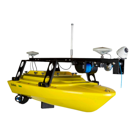
The Seafloor EchoBoat offers dual-DC motors for ease of control and redundancy, non-corrosive materials, an
integral transducer well, and multi-sensor payload capability. It allows the hydrographic surveyor to reliably and
effectively tackle hydrographic surveys in shallow waters or difficult to reach areas when conventional survey boats
are not an option.
The EchoBoat is a multi-payload, remotely controlled survey boat, featuring portability, improved thrust and large
payload capacity. The vehicle combines workhorse utility and capability with modern, advanced microelectronics
making owning and operating an RCV affordable to all in the Hydrographic Community.
If you are adding the optional AutoNav™ Auto Pilot Module:
The survey vehicle can be monitored while under way, in both Auto and Manual modes. The mission planner
application runs on a base station laptop, connected through a radio telemetry link, and displays the vehicle’s
graphical positioning and progress against a background map of the survey area. Battery voltage, current, and
capacity remaining may be monitored via this link.
Switching from autonomous to remote control is easy using a high-power remote control system that offers up to
2km range, with a survey endurance of over eight hours on a single battery pack.
2.0 EchoBoat Safety and Cautions
Always practice caution when working with electricity in water and with the spinning blades of the propeller. The
propellers can rotate up to 3,800 RPM and produce 350 W at a Max Thrust of 11.2 lbf each. Keep body parts
away from the thruster inlet and outlet to avoid injury.
Do not operate the thrusters for an extended period out of water. The bearings are lubricated by the water and
vibration and noise will be greater when dry.
The thrusters can handle saltwater and sandy environments pretty well; however, avoid sucking seaweed into the
thruster to prevent damage.
A slight clicking noise is normal, especially when operated dry. It is caused by slight movement of the shaft in the
plastic bearings.
When powering up the EchoBoat, always turn on the remote control transmitter before powering the boat. If,
when powered up, the receiver on the boat does not detect a controller signal, the remote control unit may
unexpectedlyenter the fail-safe mode. This could be extremely dangerous.
Conversely, when shutting down, always power down the boat using the ON/OFF switch on the rear of the boat
before shutting down the RCU. Again, if the remote control unit is shut off before the boat, unexpected and possibly
very dangerous maneuvers may occur.
Improperly installed instruments can cause the boat to fill with water. Never try to operate the EchoBoat without
properly installed instruments.
Do not tamper with the closed systems on the EchoBoat. Opening these items WILL VOID THE WARRANTY.

Page 4
EchoBoat-G2-RCV Quick Guide/User Manual Rev 2 AUG 2017
© Copyright 2017 Seafloor Systems, Inc. All rights reserved.
!
!
3.0 EchoBoat Specifications
Typical Survey Speed …………………… 3 kts (1.5 m/s)
Top Speed ……………………………… .. 10 kts (5 m/s)
Hull Length ……………………………….. 168cm (66 in)
Hull width ………………………….....…. 79 cm (31 in)
Battery Endurance at Survey Speed ....... 8 hrs
Battery Endurance / ASV Option ……….. 5 hrs / 27km
Payload …………………………………… 34 kg / 75 lbs
Motor Power……..………………………… 4x 14v 16Ah battery LiPo
Motor ……………………………………… 2x brushlessthruster
Hull Material ……………………………… UV resistant HDPE
Steering …………………………………… Differential
Empty Hull Weight ……………………….. 23 kg / 46 lbs
Equipment Power ………………………….3x 22v 16amp LiPo
Hardware ………………………………… Stainless steel
Remote Control Unit …………………….. Futaba 2.4 GHz long range
Remote Antenna ……………………….... Omnidirectional
Remote Range …………………………… 2 km
GPS ……………………………………… Customer specified
Communications …………………………. Bluetooth radio modem or 900 MHz spread spectrum radiomodem
Depth Sounder Transducer ………….... Through hull mount
4.0 EchoBoat Optional Instrumentation
Sonar
Multibeam echosounder
Singlebeam echosounder
Dual Frequency echosounder
Side Scan Sonar
ADCP
GPS
RTK/GNSS
Differential GPS
Auxiliary
Sound Velocimeter
Sound Velocity Profiler (SVP)
CTD Instrument
Wi-Fi remote desktop
Auto Pilot Module
AutoNav Control System
Embedded GPS and Compass
Built-in Telemetry System
PC Laptop
Mission Planner Application
USB Radio Telemetry

Page 5
EchoBoat-G2-RCV Quick Guide/User Manual Rev 2 AUG 2017
© Copyright 2017 Seafloor Systems, Inc. All rights reserved.
!
!
5.0 EchoBoat Assembly and Installation
This section provides a list of items included in the EchoBoat-G2-RCV, as well as instructions for properly charging
and installing the batteries, the antenna mast, and omnidirectional antenna.
5.1 Items shipped with the EchoBoat
• Differential Thruster Motors (x2)
• Futaba® Remote Control Transmitter with AA Batteries (x4)
• Speed Controller (x2)
• Receiver
• Motor Batteries, 14.8v, 16ah (x4)
• EchoBoat PC / sensors batteries, 22.2v, 16ah (3x)
• 4-Channel Battery Charger
• Cabling for Batteries, Remote Control System, Omnidirectional Antenna
• Internal Equipment Deck
• Access Hatch
• Handle with Hardware (x4)
• Tow/Tie-Off Ring
• Fin/Skeg with Locking Pin (x2)
• Bolts for GPS Antenna on the Mast (x2)
• Omnidirectional Antenna for the WiFi Bridge (requires assembly)
• Antenna Mast with Forward/Aft Mast Supports, Lifting Hook, Hardware (requires assembly)
5.2 Charging the Battery Systems
It is important to ensure each battery system is fully charged before deployment. Operational endurance of the thruster
batteries between charges is up to 8 hours, depending on operating speed and payload.
The Futaba T6K transmitter uses four (4) standard ‘AA’ batteries. We recommend keeping a supply of extra batteries
for fieldwork.
Each LiPo battery pack comes with a pre-installed XT90 plug and a Balance connector. (See Figure 1).
The 4-channel battery charger features four individual charging circuits (see Figure 2). It allows four batteries to
charge simultaneously. Follow the Warnings and Safety Notes in the battery charger’s operating manual.
Figure 1—LiPo battery pack comes
with XT90 plug and Balance connector.
Figure 2—A four-channel battery
charger features four individual charging
circuits.
Connecting Batteries to the Charger
If the EchoBoat was shipped with the batteries pre-installed, disconnect the connectors from the batteries, and remove
the battery packs from the hull of the EchoBoat. Follow the next steps for each battery:

Page 6
EchoBoat-G2-RCV Quick Guide/User Manual Rev 2 AUG 2017
© Copyright 2017 Seafloor Systems, Inc. All rights reserved.
!
!
1. Place the charger and batteries on a heat-resistant, non-flammable and non-conductive surface. Never charge on
a car seat, carpet or similar surface. Keep all flammable or volatile materials well away from operating area, in a well-
ventilated area, away from flammable hazards.
2. Connect the battery’s XT90 plug to the charger’s XT90 lead connector (see Figure 3).
3. Connect the battery’s Balance connector to the charger’s Balance connector (see Figure 3).
Figure 3—Connect the battery’s XT90 plug and Balance connector to the charger’s XT90 lead and Balance connectors.
Display/Adjust Each Battery’s Setting
After connecting the battery leads and balance connectors to the charger, connect the charger’s AC cord to the outlet to
power up the battery charger. The charger settings for each battery (channel) should have been pre-set with the following
settings:
Type of battery: LiPo BATTERY
Type of charge: LiPo BALANCE
Amperage: 1.5A
Voltage: 14.8v
Follow the instructions in the next steps to display each battery’s settings, and make any adjustments as required.
Note: When the charger is powered off and then on again, the previously activated settings should be displayed.
Select the Channel
Starting with the first battery
To view the charge settings, press the CHANNEL button to cycle through until the correct channel light is illuminated for
that battery. Each time the button is pressed, a RED light will be illuminated for the next channel. For example, settings for
the left-most battery are displayed in the window when the left-most light is illuminated (see Figure 4-LEFT).
Figure 4—LEFT, MIDDLE: Press CHANNEL to illuminate the desired circuit, then confirm by pressing ENTER. Press INC button, cycle through
until the correct type of charge is shown (“BALANCE”), then confirm by pressing ENTER. RIGHT: Battery label indicates “4S/14.8V”.
Select Type of Charge
To ensure the type of charge is LiPo BALANCE, press the INC button several times to cycle through charging options.
Select LiPo BALANCE (see Figure 5-MIDDLE). Press ENTER.

Page 7
EchoBoat-G2-RCV Quick Guide/User Manual Rev 2 AUG 2017
© Copyright 2017 Seafloor Systems, Inc. All rights reserved.
!
!
Select or Adjust Ampere Rate
The screen will display the Ampere and Voltage rates (see Figure 6-LEFT).
Press the DEC or INC button to cycle through and adjust the ampere value to 1.5A.
Press START/ENTER to confirm the values are set.
Note: the slower the charge, the longer life of the charge and the battery. We recommend 1.5A.
Select Voltage Rate
The battery manufacturer has labeled the battery as “14.8v / 4S” for the motor batteries and 22.2v /6s for the
equipment / sensor batteries, which is used to determine the charging preferencein these instructions (see Figure 5).
The screen displays the new ampere rate, and ready to accept or confirm the voltage rate.
Figure 5—LEFT, Figure 6—MIDDLE: Ampere and Voltage values are displayed and
can be changed using the INC or DEC buttons, then confirm by pressing ENTER.
Press INC or DEC to cycle through and select 14.8 (4S) voltage rate (see Figure 6-MIDDLE).
Press ENTER, and hold for 2 seconds; 3 beeps.
The screen indicates a battery check is being performed.
Confirm by pressing ENTER; listen for a tone that will confirm the setup to be complete.
The display will indicate the setup is complete for that channel/battery (see Figure 7).
Make sure to battery check every channel to ensure every battery will be charged.
**IMPORTANT** Ensure the Capacity Cut-Off is ON and at 16000Ah. We pre-set this in our process but this
should be checked by the end user. See the charger manual for more information.
View All Settings for that Channel (Battery)
Press the INC button to view settings for that channel.
The display will show all charging information for each cell of the battery on that channel (see Figure 7).
Repeat Steps for Remaining Batteries/Complete the Charge
Repeat steps 5.2.3 to 5.2.7 for the remaining three batteries.
When charging is complete, the system will emit a tone.
IMPORTANT!
• Verify that the charger’s input power requirements are compatible with your region’s line
voltage before proceeding with these instructions.
• Batteries should be supervised while charging and should not be left unattended. Ensure that the
batteries are disconnected as soon as charging is complete.
• Do NOT overcharge the batteries! We have PRE-SET the charger to that the batteries cannot
be overcharged; HOWEVER, it is up to the end user to ensure the settings are correct to
prevent explosion or fire.
Figure 7—The display indicates the values that
have been set after confirming.
!

Page 8
EchoBoat-G2-RCV Quick Guide/User Manual Rev 2 AUG 2017
© Copyright 2017 Seafloor Systems, Inc. All rights reserved.
!
!
5.3 Installing the Battery System in the EchoBoat
If the battery packs were shipped separately, or not pre-installed, follow these steps:
•Load the four LiPo batteries onto the battery panel in the EchoBoat hull, with the leads facing the transducer
well.
•Connect all four XT90 power plugs into the EchoBoat’s XT90 plugs (see Figure 8).
Figure 8—Install the four LiPo batteries onto the battery panel in the EchoBoat hull. Snap the belt around the batteries and tighten. RIGHT:
Connect all four XT90 power plugs into the EchoBoat’s XT90 plugs.
5.4 Installing the Antenna Mast
•Remove the Aft Handles from the boat. Place the Aft Mast Support under the Aft Handles and bolt using
the same hardware. Repeat the procedure with the Forward Handles and Forward Mast Support.
•Attached the Antenna Mast to the Aft/Forward Mast Supports using the hardware provided, making sure it is
properly positioned, as shown in Figure 9.
Figure 9—Assemble the Antenna Mast, ensuring the WiFi and Transducer openings are properly aligned.
5.5 Assembling the WiFi/Omnidirectional Antenna
The Omnidirectional Antenna provides long range telemetry—it comes in two parts: a long pole, for onshore laptop,
and a short pole, to install on the Antenna Mast, through the WiFi Antenna mounting point (see Figures 9, 10).
Figure 10—Omnidirectional Antenna for a telemetry system.
WiFi Antenna mounting point
Antenna mounting point #3
Forward section of Antenna Mast is longer in length than section.
Antenna Mast assembly
·5/16-18 3/4” Socket Cap Screw
·5/16-18” Nut
·5/16” Flat asher
·5/16” Lock asher

Page 9
EchoBoat-G2-RCV Quick Guide/User Manual Rev 2 AUG 2017
© Copyright 2017 Seafloor Systems, Inc. All rights reserved.
6.0 Powering Up the EchoBoat
Before powering up the EchoBoat, follow the instructions in Section 7.
6.1 The Futaba Remote Control Unit (RCU)
This section describes a method of arming the system.
The EchoBoat is pre-installed with a Futaba RCU and consists of the following components (see Figure 11):
Futaba Remote Control Unit
2 Speed Controllers (1 for each Thruster)
1 Receiver
Receiver
Channel 5 Switch
UP = Manual
DOWN = Autonomous (optional) Speed Controllers
LEFT Throttle Stick
Before turning on the remote
control unit, both throttle sticks
should be in CENTER position.
Figure 11—Operation features of the Futaba® Remote Control
Unit
RIGHT Throttle Stick
Before turning on the remote
control unit, both throttle sticks
should be in center position.
ON Switch
6.2 Setting up the boat
A. Lay the boat into the water.
***IMPORTANT*** The joysticks must be in MIDDLE position prior to next step.
B. Place the Futaba joysticks in the MIDDLE position.
6.3 Setting up the Futaba RCU Controls
A. Turn on the Futaba RCU. Continuous pulsating chimes will be audible, and a warning signal will appear
in the window:
WARN-THR
B. Slowly move the LEFT joystick to DOWN position, then back to MIDDLE position. The system is
now armed, ready to operate.
Note: When the system is functioning properly, two chimes will be audible after positioning the LEFT
joystick from MIDDLE to DOWN to MIDDLE position. If continuous pulses of chimes are heard, please refer to the
HyDrone Video Troubleshooting Guide, in the CD included in the shipment, or follow this link:
https://www.youtube.com/watch?v=HOdkXY_Ik7w&feature=youtu.be
6.4 Futaba RCU Operational Modes
UP
=
Forward
MIDDLE
=
Neutral
DOWN
=
Reverse
Also, refer to Section 10—Troubleshooting, for more information on the Futaba RCU.

EchoBoat-G2-RCV Quick
Page 10
Guide/User Manual Rev 2, AUG. 2017
© Copyright 2017 Seafloor Systems, Inc. All rights reserved.
6.5 Final Steps in Preparation
A. Flip the boat’s ON/OFF switch to ON position.
B. Wait approximately 15 seconds for speed controllers to pair; they will go through a series of tones.
C. Test each joystick to ensure the left and right propellers are running at the same speed. If both
propellers are spinning at the same rate, proceed to configure the GPS and depth sounder.
D. Check the GPS antenna and data collector are functioning.
E. Begin the survey.
7.0 The EchoBoat-ASV is equipped with a Mission Planner application that runs on a base station laptop,
connected through a radio telemetry link. It displays the vehicle’s graphical positioning and progress against a
background map of the survey area. Battery voltage, current, and capacity remaining are monitored via this link.
7.1 Connecting the Hardware
Note: Always make sure the AutoNav Control Module is charged before starting a survey. Plug the end of the
charger cable to the AutoNav Port connector. The charger will have a blinking green light to indicate the module
is charging. A solid green light indicates a fully charged battery system.
A. Attach the AutoNav Control Module to the marine board inside the EchoBoat—see Figure 12.
B. Plug the Port EchoBoat cable into the AutoNav Port connector—see Figure 13.
Note: be careful when plugging in the male connectors—they are fragile. If the pins
get bent and cross, they will cause a short somewhere in the system.
C. Plug the Starboard EchoBoat cable into the AutoNav Starboard connector—see Figure 13.
D. Attach the Radio Telemetry Antenna to the AutoNav.
E. Turn the AutoNav to the ON position
Figure 12—Attach the AutoNav Control Module to
the marine board inside the EchoBoat.
Figure 13—Plug the Port and Starboard cables
into the AutoNav Control Module.

EchoBoat-G2-RCV Quick
Page 11
Guide/User Manual Rev 2, AUG. 2017
© Copyright 2017 Seafloor Systems, Inc. All rights reserved.
7.2 Launching Mission Planner Application on Laptop
A. Plug in the USB Radio Telemetry to the laptop—see Figure 14.
B. Launch Mission Planner application from the desktop shortcut on the laptop.
C. Select COM port (top right corner of the screen)—see Figure 15.
D. Set Baud Rate to 57600—see Figure 15.
E. Click on the Connect tool—see Figure 15.
Figure 14—Attach the USB Radio Telemetry to the Figure 15—Select COM port in Mission Planner application and
Mission Planner Laptop
7.3 Setting up Survey/Waypoints (WPs)
A. Locate the survey area on the map.
B. Zoom in on the survey area.
C. Click on the Flight Plan tool (upper left of the tool bar)—see Figure 16.
D. Click the Home Location button to set Home (right side of screen)—see Figure 16.
E. Click on the map to add Waypoints—see Figure 17.
F. Click on Write WPs to upload to the AutoNav (right side of screen)—see Figure 17.

EchoBoat-G2-RCV Quick
Page 12
Guide/User Manual Rev 2, AUG. 2017
© Copyright 2017 Seafloor Systems, Inc. All rights reserved.
Figure 16-Click on Flight Plan tool (upper left of toolbar)
Figure 17-Add Waypoints by clicking on the map.
7.4 Conducting Compass Calibration
Note: AutoNav is required to be powered on for this procedure.
Calibrate the compass each time each time the survey location has beenchanged.
A. Click on Initial Set-up tool (top left)—see Figure 18.
B. Click on Mandatory Hardware—see Figure 18.
C. Click on Compass-see Figure 18
D. Start Live Calibration under Mission Planner Mag Calibration—see Figure 18.
E. Manually rotate the AutoNav Control Unit, around all axis, per instructions on
screen.
Note: this needs to be done outdoors.
F. When Calibration is completed, the program will beep as notification. Click
OK.

EchoBoat-G2-RCV Quick
Page 13
Guide/User Manual Rev 2, AUG. 2017
© Copyright 2017 Seafloor Systems, Inc. All rights reserved.
Figure!18—Click!on!Initial!Set5up!tool.!
Click!on!Mandatory!Hardware.!
Click!on!Compass.!
Start!Live!Calibration!under!Mission!Planner!Mag!Calibration.!
7.5 Arming the AutoNav Control Unit
A. Ensure both remote throttle sticks are in CENTER position—see Figure 18.
B. Ensure the channel 5 switch is in the UP position (Manual Mode)—see Figure 18.
C. Turn the Remote Control Unit to the ON position (it will beep rapidly)—see Figure 18.
8.0 Launching and Retrieving the EchoBoat
The EchoBoat should be launched stern (rear end) first. This will protect the thrusters from accidentalgrounding
and possible damage.
•Thoroughly familiarize yourself with the way the boat responds to the controls before deploying in fast-
moving water.
•When the boat is traveling away from you it will respond to control signals as expected, however when
the boat is inbound (traveling toward you), the same control signals create an inverted
response. An inexperienced operator’s first response in an emergency may unintentionally guide the
boat in an unintended direction.
•To prolong the life of the batteries, accelerate slowly.

EchoBoat-G2-RCV Quick
Page 14
Guide/User Manual Rev 2, AUG. 2017
© Copyright 2017 Seafloor Systems, Inc. All rights reserved.
9.0 Maintenance
The EchoBoat is designed to be easy to maintain. Obey the following tips to prolong the life of the EchoBoat and
its components.
Hull
To prolong the life of the HDPE hull and finish, wash with mild soap and water after each use.
Thrusters
The EchoBoat comes with pre-installed brushless differential thrusters (see Figure 19).
** IMPORTANT! **
Don’t run the thrusters at high speeds or for extended period out of water
to minimize noise and wear.
Rinse after use in saltwater and clean out bio fouling and debris occasionally.
Figure 19—The EchoBoat comes with two pre-installed brushless differential thrusters.
Access Hatch
Check the access hatch gasket for cuts, cracks or deformation. This gasket seals the instrumentation area from water
intrusion and should be checked frequently.
10.0 Troubleshooting
Many common mistakes require recalibration these mistakes may include:
!Turning on power to the thrusters while the joysticks are NOT the in MIDDLE position.
!Neutral not being properly set on the Futaba remote.
!Propellers spinning at different speeds.
!
See section 10.1 to recalibrate the Futaba Remote

EchoBoat-G2-RCV Quick
Page 15
Guide/User Manual Rev 2, AUG. 2017
© Copyright 2017 Seafloor Systems, Inc. All rights reserved.
10.1 Futaba Remote Calibration
1. Turn OFF the power to the thrusters.
2. Turn OFF Futaba RCU.
3. Joysticks in the MIDDLE position.
4. Turn on Futaba RCU, and make sure it is armed (follow steps in Section 7).
5. RIGHT joystick all the way FORWARD.
6. Turn ON the power to the thrusters, focus on the right thruster only. Two chimes.
7. Bring RIGHT joystick back to NEUTRAL (MIDDLE position). Three chimes. System is calibrated.
8. Turn OFF the power to the thrusters.
9. Repeat Steps 1 through 7 focus on the LEFT thruster and LEFT joystick.
10. If more than three chimes are heard, repeat the process.
These steps are shown in the HyDrone Video Troubleshooting Guide
https://www.youtube.com/watch?v=HOdkXY_Ik7w&feature=youtu.be
10.2 Pairing the Futaba Remote
If the Futaba RCU continues to chirp more than two times when turning it on, follow these instructions to re-pair the
RCU with the speed controller:
1. Turn on Futaba RCU and hold it close proximity to the speed controller in the rear of the boat.
2. Turn on the power to the thrusters, and focus on the one that needs to be paired.
3. Locate the speed controller in the boat. Press and hold the small black button labeled “SW” for
approximately 3 seconds.
The RED flashing light indicates it is searching to pair with a Futaba RCU.
Note: If the RED light continues to flash, the Futaba RCU may be too far away to pair.
Even 1 foot away may be too far to pair.
The GREEN solid light indicates it has discovered the Futaba RCU.
11.0 Contacting Technical Support:
Phone: (530) 677-1019
Email: info@seafloorsystems.com
Hours: Monday - Friday, 8:30 a.m. - 5:00 p.m. Pacific Time
Address: 4415 Commodity Way, Single Springs CA 95682

EchoBoat-G2-RCV Quick
Page 16
Guide/User Manual Rev 2, AUG. 2017
© Copyright 2017 Seafloor Systems, Inc. All rights reserved.
12.0 EchoBoat-G2 Warranty
Seafloor Systems, Inc. makes every effort to assure its products meet the highest quality, reliability and durability
standards and warrants to the original purchaser or purchasing agency that each EchoBoat be free from defects in
materials or workmanship for a period of one year from date of shipment.
Warranty does not apply to defects due directly or indirectly to misuse, negligence or accidents, repairs or alterations
outside of our facilities, use of the EchoBoat for purposes other than water measurements, or use with instruments
weighing more than 75 lbs.
Seafloor is not responsible for loss of boat, instruments, damage to property, injury or death associated with the use of
any of its products or products that may be included or used with Seafloor products. Seafloor does not provide any
warranty for third party products sold by Seafloor. These may include GPS, depth sounders, and other ancillary
equipment.
WARRANTY IS VOIDED WITH THE TAMPERING OF CLOSED ELECTRONIC COMPONENTS.
All warranty services are FOB Seafloor’s facility in Shingle Springs, California, U.S.A.
13.0
Seafloor Systems, Incorporated
4415 Commodity Way, Shingle Springs, CA 95682 ·USA
(530) 677–1019 | [email protected] |

EchoBoat-G2-RCV Quick
Page 17
Guide/User Manual Rev 2, AUG. 2017
© Copyright 2017 Seafloor Systems, Inc. All rights reserved.
This manual suits for next models
1
Table of contents
Other Seafloor Measuring Instrument manuals
Popular Measuring Instrument manuals by other brands

Spectral Products
Spectral Products CM110 manual

MKS
MKS Granville-Phillips Mini-Convectron 275... instruction manual

Neutronics
Neutronics ULTIMA ID PRO RI-700H Operation manual

HP
HP 548A Operating and service manual

Kobold
Kobold HND-R106 Original instructions

LeCroy
LeCroy LogicStudio Getting started manual