Seagull MAP-X2 User manual

Product: Seagull #MAP-X2
Released: 2020-04-20
FW: 2.0
Seagull #MAP-X2
User Manual

© 2020 Seagull UAV All Rights Reserved. 2
CONTENTS
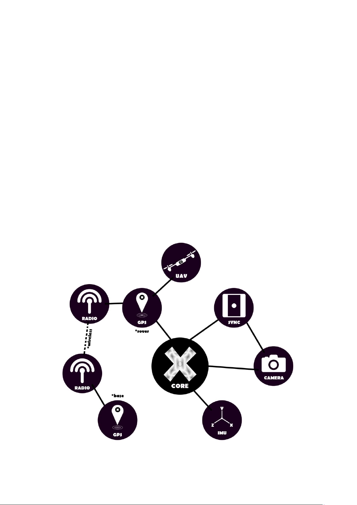
GENERAL INFORMATION..................................................................................................................................................................... 3
TRIGGER MODES & COMMANDS........................................................................................................................................................ 4
SST ........................................................................................................................................................................................................... 4
ACT-PWM................................................................................................................................................................................................. 4
ACT+PWM ................................................................................................................................................................................................ 4
TIMELAPSE............................................................................................................................................................................................... 4
BUTTON.................................................................................................................................................................................................... 5
CAMERA ON/OFF ..................................................................................................................................................................................... 5
LOG START/END ...................................................................................................................................................................................... 5
CH1 & CH2 COMMAND TABLE ........................................................................................................................................................... 5
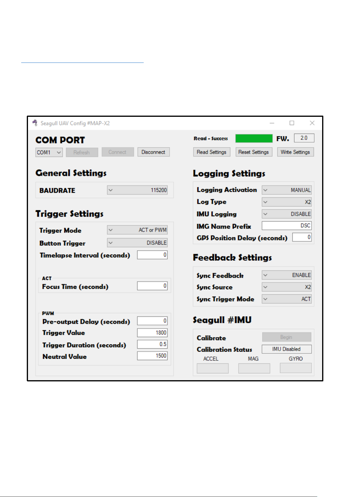
CONFIGURING #MAP-X2..................................................................................................................................................................... 6
GENERAL.................................................................................................................................................................................................. 6
SETTINGS AND VALUES TABLE........................................................................................................................................................... 7
FLIGHT CONTROLLER INTEGRATION................................................................................................................................................... 8
PIXHAWK.................................................................................................................................................................................................. 8
DJI A3 ....................................................................................................................................................................................................... 8
R/C TRANSMITTER INTEGRATION ....................................................................................................................................................... 9
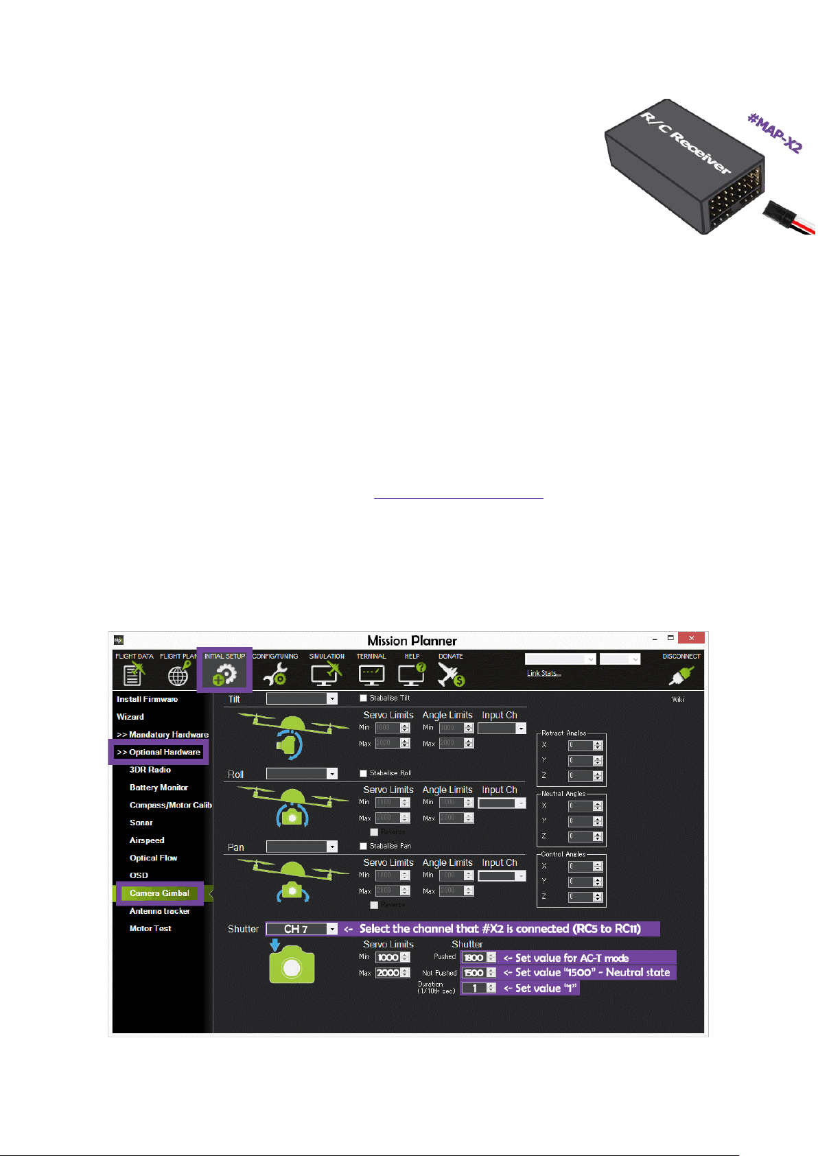
FLIGHT PLANNER SOFTWARE INTEGRATION ...................................................................................................................................... 9
MISSION PLANNER.................................................................................................................................................................................. 9
DJI ASSISTANT 2.................................................................................................................................................................................... 10
PORT / PIN DEFINITIONS................................................................................................................................................................... 11
TROUBLESHOOTING.......................................................................................................................................................................... 11
TECHNICAL SPECIFICATIONS ........................................................................................................................................................... 11

© 2020 Seagull UAV All Rights Reserved. 3
GENERAL INFORMATION
*** Please read this manual thoroughly before connecting and configuring Seagull #MAP-X2 ***
Seagull #MAP-X2 is a precision camera trigger controller and logger. #MAP-X2 uses your cameras´ hotshoe/event pin for feedback
and GNSS data to log exact coordinates of when the photo was captured, resulting in a 1:1 ratio between coordinates and photos.
#MAP-X2 can receive GNSS data via Seagull UAVs´ GNSS receiver products or other GNSS receivers capable of providing necessary
messages, that are recognized by #MAP-X2 for data logging.
NOTE: #MAP-X2 can also log GNSS data without a SYNC event feedback.
#MAP-X2 features:
•High data rate sampling –4Hz MB, 5Hz RTK, 10Hz RAW, 10Hz GNSS
•Various trigger modes –SST, ACT, PWM, BUTTON, TIMELAPSE
•Trigger and Log –with or without SYNC feedback
•Easy geotagging –Pix4D, EXIF
•IMU compatible –improves ORTOPHOTO and 3D Model processing
•GNSS receiver messages supported –UBX-NAV-PVT / UBX-RXM-RAWX + UBX-RXM-SFRBX

© 2020 Seagull UAV All Rights Reserved. 4
TRIGGER MODES & COMMANDS
SST
(Shoe Sync Trigger)
When operating in SST mode, #MAP-X2 will wait for a SYNC event (hotshoe/event feedback) and will log the data when supplying a
LOW (0 volt) condition to the SYNC pin.
SST mode is designed for a scenario where the user is triggering a camera by pressing the shutter button to capture a photo, then the
SYNC signal is sent to #MAP-X2, telling that there was a shutter event on the camera, and #MAP-X2 will write coordinates and other
data to the log files.
NOTE: This mode is not only limited to a MANUAL TRIGGERING scenario. For example - if you wish to have control functionalities
from Seagull #REC / #REC2 and the precision of #MAP-X2 for logging. You may achieve such functionality by using #MAP-X2 in SST
mode to handle the logging and simply use one #REC / #REC2 to handle the shutter release and other aspects of the camera.
ACT-PWM
(Autofocus Custom Trigger - Pulse Width Modulation)
This is the default trigger mode for #MAP-X2. When operating in this mode #MAP-X2 enables ACT mode on HIGHER and PWM mode
on LOWER end of signals for CH1 input.
ACT mode is meant for use to trigger cameras that are connected to a camera port on the #MAP-X2, that are
listed on the: #MAP-series cable finder
PWM mode is meant to trigger cameras that use PWM signal as a command for triggering, such as the FLIR VUE Pro thermal camera.
ACT+PWM
(Autofocus Custom Trigger + Pulse Width Modulation)
When operating in this mode it enables both modes ACT and PWM to trigger either on HIGH or LOW end of signal for CH1 input.
ACT mode is meant for use to trigger cameras that are connected to a camera port on the #MAP-X2, that are
listed on the: #MAP-series cable finder
PWM mode is meant to trigger cameras that use PWM signal as a command for trigger, such as FLIR VUE Pro thermal camera.
NOTE: When operating in this dual trigger mode, #X2 will wait out until all trigger conditions that are set in settings are met. For
example, in a case when SYNC is enabled for AC-T mode and PWM DURATION set to 0.5(seconds): if ACT SYNC event happens
before PWM DURATION is over –then #MAP-X2 will log coordinates and wait the remaining time of PWM DURATION before allowing
next user input.
TIMELAPSE
(Interval trigger)
Timelapse will only be active when there is a value present in settings of #MAP-X2 and will work with the user input interval value for
the following trigger modes: ACT –PWM, ACT + PWM and BUTTON mode.
If the value is set as 0, only a single photo will be captured.
If value is set for example 0.5(seconds) #MAP-X2 will keep taking photos as long as the selected trigger mode is kept in its activation
value (PWM input value).

© 2020 Seagull UAV All Rights Reserved. 5
BUTTON
(Support for an external button for triggering)
BUTTON mode is activated by providing a LOW state (0 volt) to the signal pin of BUTTON channel. When signal is present it will
execute a trigger mode that is setup in the settings. Following trigger modes are compatible ACT / PWM, ACT and PWM.
This mode is very useful in a scenario where the user wishes to log and execute triggering commands by a push of a button or simply
supplying constant LOW state and using with TIMELPASE setout INTERVAL for continuous photo triggering.
CAMERA ON/OFF
(Feature to control power on/off)
CAMERA ON/OFF command is very useful in scenarios where you have retractable lenses or wish to protect from dust before takeoff
or during landing scenarios.
NOTE: Only available with camera cables listed as "Sony S2 w. on/off" for Sony "MULTI" enabled cameras.
LOG START/END
This command must be executed in order for #X2 to generate log files. #X2 will only start log generation once the command LOG
START/END has been executed. The LOG START/END can be executed via the following options:
Sending "1800"μSsignal to #MAP-X2 via CH2.
Clicking the "LOG" button on #MAP-X2.
Setting "Logging Activation" to "AUTO" in the settings
CH1 & CH2 COMMAND TABLE
CHANNEL
STATE / MODE
ACTIVATION VALUES
SCOPE
CH1
PWM / ACT+PWM
1200 μS
1000 <> 1400 μS
CH1
AC-T / ACT+PWM
1800 μS
1600 <> 2000 μS
CH2
CAMERA ON / OFF *
1200 μS
1000 <> 1400 μS
CH2
LOG START / END
1800 μS
1600 <> 2000 μS
CH1, CH2
NEUTRAL
1500 μS
1400 <> 1600 μS
CH1 / CH2
SIGNAL NOT IN RANGE **
n/a
1<> 1000 μS μS / 2000 <> ∞μS
CH1 & CH2
NO SIGNAL ***
n/a
0 μS
*ON/OFF only for Sony "Multi" cameras with SMAP-
3009/3010 cable!
** Signal not in range will occur when there is signal present,
but it is not within any operational modes.
*** There is no input signal detected.

© 2020 Seagull UAV All Rights Reserved. 6
CONFIGURING #MAP-X2
GENERAL
#MAP-X2 can be configured by “Seagull-MAP-X2-Config.exe” that can be downloaded via the following link:
https://www.seagulluav.com/seagull-map-x2-support/
Please use the C USB Port on #MAP-X2 to configure.
Seagull #MAP-X2 Configurator example photo

© 2020 Seagull UAV All Rights Reserved. 7
SETTINGS AND VALUES TABLE
SETTING NAME
SETTINGS
RANGE
DEFAULT
DESCRIPTION
GENERAL SETTINGS
Baudrate
Value
1200 -
960000
115200
Baud rate setting used for communicating with GNSS receiver connected to
#MAP-X2 –MUST BE SAME VALUE AS GNSS RECEIVER BAUD RATE
TRIGGER SETTINGS
Trigger Mode
SST / ACT or
PWM / ACT
and PWM
n/a
ACT or PWM
Selection of which trigger mode #MAP-X2 should work in. Read section
"TRIGGER MODES & COMMANDS" for description of each individual mode
Button Trigger
DISABLE /
ACT / PWM /
ACT and PWM
n/a
DISABLE
Button trigger works when enabled in one of the modes and triggered at 0V
on the SIGNAL line of the BUTTON INPUT PORT.
Timelapse Interval
Value in
seconds
0 –to
disable
0.1 <>
*alot
(9e+15)
0
When set to 0 TIMELAPSE mode is disabled. If value is higher than 0 and
within range, #MAP-X2 will keep triggering until the Trigger mode is exited.
Following modes are supported: ACT-PWM, ACT+PWM and BUTTON.
ACT
ACT Focus Time
Value in
seconds
0 <> *alot
(9e+15)
0
ACT pre-focus time will focus the camera for a period of time and then activate
shutter release. Its best to keep it at 0 and use MANUAL focus on the
cameras' settings.
PWM
PWM Pre-output Delay
Value in
seconds
0 <> *alot
(9e+15)
0
A delay before executing PWM output commands for triggering the camera.
PWM Trigger Value
Value in μS
550 <>
2400 μS
1800 μS
Trigger value in microseconds that is accepted by your PWM signal driven
camera for shutter or other mode activations.
PWM Trigger Duration
Value in
seconds
0 <> *alot
(9e+15)
0.5
How long the PWM trigger value should be outputted before returning to
NEUTRAL mode.
NOTE: If SYNC is enabled and event occurs, PWM NEUTRAL is executed and
PWM duration ends.
PWM Neutral Value
Value in μS
550 <>
2400 μS
1500
NEUTRAL value for your PWM camera, meaning that when set in this value it
will not execute anything and wait for trigger value to occur again.
LOGGING SETTINGS
Logging Activation
MANUAL /
AUTO
n/a
MANUAL
Can be enabled to AUTO logging start and end. When there is a signal present
on CH1 which is above 999 μS and below 2001 μS, #MAP-X2 will start log
generation. When the signal is out of these ranges it will end log and write the
data to the microSD card.
Log Type
X2 / PPK / X2
and PPK
n/a
X2
X2: Pix4D, X2, KML, SUM
PPK: PPK, SUM
X2 and PPK: All the above logs generated
IMU Logging
ENABLE /
DISABLE
n/a
DISABLE
If IMU is present and enabled, #MAP-X2 will log extra fields in Pix4D and X2
logs with roll, pitch and yaw.
Image Name Prefix
USER INPUT
etc. "DSC"
n/a
DSC
Input the filename prefix used on photos by your camera. #MAP-X2 will log
image filename with the following: filename + confirmed photo count etc.
Example: "DSC00001.JPG"
GPS logging delay
Value in
seconds
0 <> *alot
(9e+15)
0
GPS logging delay is set to delaying logging of the coordinate after the camera
has been triggered. Very useful in scenarios where there is no SYNC
feedback, so you can time approximately how long it takes for camera to
capture photo and then execute to log coordinate by #MAP-X2.
FEEDBACK SETTINGS
Sync feedback
ENABLE /
DISABLE
n/a
ENABLE
ENABLE or DISABLE SYNC feedback for precise logging.
NOTE: LOW (0 volt) state indicates a SYNC event.
Sync Source
X2 / GNSS
n/a
X2
Choose whether the #SYNC2 (HOTSHOE) is connected to a #MAP-X2 or
GNSS receiver. If GNSS is selected please make sure that it is able to output
UBX-TIM-TM2 message, as an indicator of an event.
Sync Trigger Mode
ACT / PWM
n/a
ACT
When using trigger mode ACT+PWM and SYNC is ENABLED, indicate which
mode your SYNC should react to - ACT driven or PWM driven camera.

© 2020 Seagull UAV All Rights Reserved. 8
FLIGHT CONTROLLER INTEGRATION
PIXHAWK
#MAP-X2 can be powered via its rails –so when connecting to Pixhawk rails, make sure there is sufficient power to supply #X2.
Maximum power that can be applied on Pixhawk 1 rails is 5.7V, follow documentation of the ArduPilot controller that you have. Its
recommended to use 5V UBEC to provide power to the rails.
DJI A3
Connect the CHANNEL that you wish to control from #MAP-X2 to the "F port" that you wish to use. DJI A3 can't provide power to the
#MAP-X2 through its rails, therefore connect only BLACK –and WHITE signal to the "F port" and power #MAP-X2 via UBEC or such
that is within power range limits for #MAP-X2.

© 2020 Seagull UAV All Rights Reserved. 9
R/C TRANSMITTER INTEGRATION
#MAP-X2 is compatible with all R/C equipment that can supply a PWM/SERVO signal operating at
50Hz and that meets the ranges set out for #MAP-X2 modes. For the modes please refer to CH1 &
CH2 COMMAND TABLE in the manual. As well check the conversion table for RC transmitters when
adjusting the channel to activate #MAP-X2 modes.
FLIGHT PLANNER SOFTWARE INTEGRATION
MISSION PLANNER
The following example is for setup where automated flight is being executed with the do_digicam_control command.
When a channel is setup via "Camera Gimbal" menu, that channel is occupied by Pixhawk and you will not be able to pass manual
trigger commands via R/C transmitter. If you wish to control the channel manually you will need to setup the RC channel as pass
through in the Mission Planner.
1. Click on INITIAL SETUP >> OPTIONAL HARDWARE >> CAMERA GIMBAL
2. "SHUTTER" - in the drop-down list, chose the channel that Seagull #MAP-X2 is connected to.
3. "PUSHED" - Set the "VALUE" for the trigger mode (CH1 & CH2 COMMAND TABLE)
4. "NOT PUSHED" –Set the value "1500" (NEUTRAL STATE)
5. "DURATION" –Set the value "1"
Example from Mission Planner:
NOTE:"Servo Limits" needs to be set to Min: "1000" and Max: "2000" for Pixhawk to react to the entered values!

© 2020 Seagull UAV All Rights Reserved. 10
DJI ASSISTANT 2
The following example sets up DJI A3 controller through DJI Assistant 2 for shutter control automated flights.
1. "SHUTTER" - in the drop-down list on the "F port" that #MAP-X2 is connected to
2. "SHUTTER TRIGGER PWM" - Set the "VALUE" for the trigger mode (CH1 & CH2 COMMAND TABLE)
3. "SHUTTER DEFAULT PWM" –Set the value "1500" (NEUTRAL STATE)
4. "SHUTTER PWM FREQUENCY " –Select "50Hz" option
5. "SHUTTER PWM ACTIVE " –Set the value to "100"
It is also possible to map a switch to have manual triggering
option, this can be done when selecting the port to operate
as "Sx" and inputting the value in LOW and HIGH range. To
achieve a NEUTRAL value for the switch it is calculated
(LOW+HIGH)/2, in the below example it is set to use "1800"
(ACT mode) and value for NEUTRAL is "1500".

© 2020 Seagull UAV All Rights Reserved. 11
PORT / PIN DEFINITIONS
PORT
DEFINITION
PINS
GPS
GNSS communication port
1: VIN (3.9 -12V)
2: RX (3.3V)
3: TX (3.3V)
4: GND
EXP
Expansion port
1: VIN (3.9 -12V)
2: RX (3.3V)
3: TX (3.3V)
4: GND
I2C
Interface for I2C modules
1: VIN (3.9 -12V)
2: SCL (3.3V)
3: SDA (3.3V)
4: GND
I2C
Interface for I2C modules
1: VIN (3.9 -12V)
2: SCL (3.3V)
3: SDA (3.3V)
4: GND
CH1
CHANNEL 1 INPUT
SIGNAL
VIN 3.9 –12V
GND
CH2
CHANNEL 2 INPUT
SIGNAL
VIN 3.9 –12V
GND
BTN
BUTTON TRIGGER INPUT
SIGNAL
VIN 3.9 –12V
GND
SYNC
SYNC FEEDBACK
SIGNAL
X2 –3.3V OUT
GND
PWM
PWM TRIGGER OUTPUT
SIGNAL
VIN 3.9 –12V
GND
GBXS
ACCESSORY PORT
S: SD LED
X: X STATE LED
B: LOG BUTTON
G: GND
LOG START/END BUTTON
Controller USB and firmware update
port. The unit can be powered via
USB as well with following ranges 4.4
–12V
N/C
VIN 3.9 –12V
GND
TROUBLESHOOTING
To determine what Seagull #MAP-X2 is currently doing - simply read the output of the "X STATE" and "SD CARD" LEDs, then match it
with the "Action" in the table below.
TECHNICAL SPECIFICATIONS
•Supply voltage: 3.9 –12V (5v recommended –do NOT exceed 12V!)
•Current draw: Min: 17mA, Average: 43mA, Max: 55mA
•Input signal: 3.3V standard R/C PWM between 1000 –2000μS
•Dimensions: 48mm x 40mm x 11mm
•Weight: 20g (without misc. cables)
X STATE
ACTION
Off
There is no signal
Blinking
Signal is present but out of range
Fading
In "Neutral" and Ready - waiting for next command
Faded
Active in a trigger mode –return to "Neutral" before next command
SD CARD
ACTION
Blinking
Micro SD card - is not present
Flashing rapidly
Micro SD card initialization error –please check format!
Fading
Micro SD card has been initialized and waiting for log to start
Solid on
Micro SD card –logging has been activated
X STATE
SD CARD
ACTION
ACTION
Blinking
Blinking
I2C device was enabled - but #MAP-X2 failed to initialize or device is disconnected
Table of contents
Other Seagull Camera Accessories manuals
Popular Camera Accessories manuals by other brands

Rollei
Rollei Rock Solid Beta user guide

UPOWER Ecoline
UPOWER Ecoline UE-24Li300 manual

Lilin
Lilin PIH-302C instruction manual

SLIK
SLIK Multi Arm III operating instructions

Gitzo
Gitzo Classic Inter Pro Studex Mk2 G1345 G1345 parts list

PowerPlus Energy
PowerPlus Energy LiFe4838P Installation and operation manual