________________________________________________________________
Sealevel Systems Latch-16 Page 3
SECTION 3. Technical Description
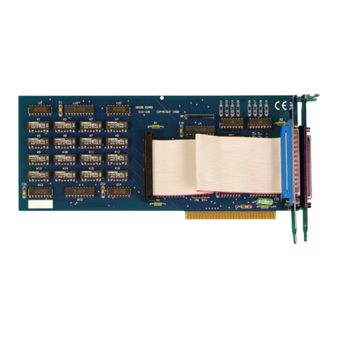
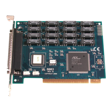
The LATCH-16 provides two eight bit latched relay output ports. Latched Relays maintain
their set or reset condition until set or reset again, regardless of power conditions. This allows
the user to set the LATCH-16 relays in a required state and power down the computer. When
a change is required, the user can simply set or reset the relay(s) again.
Note: The terms “set” and “reset” are used to define the state of the relay. Set means that the
relay “S” coil has been energized, and the relay contacts are closed. Reset means that the
relay “R” coil has been energized, and the contacts are open.
The Latch-16 is easily programmed as simple Port I/0. To set a relay, the corresponding bit in
Base+0 (or Base+2) must be written as a “0”. To reset a relay, the corresponding bit in
Base+1 (or Base+3) must be written as a “0”. Writing to any of these registers causes a 6
mS. (Millisecond) pulse generator to energize the relay coil. This particular hardware
approach was chosen to keep the controlling software from having to use timing routines and
perform tedious I/O operations.
Note: While setting or resetting individual bits requires only one I/O write, writing
a byte of data to the port requires writing both the set and reset register. This
is because only the “0” bits in the byte cause a set or reset operation.
Therefore, to write a byte (55 Hex) to Port A, first write a 55H to Base+0 and
write the complement (AA Hex) to Base+1.
Output Functions: Input Functions:
Base+0 Set relays on Port A (Relays K9-K16) Read status of relays K9-K16.
Base+1 Reset relays on Port A (Relays K9-K16) Read status of pulse generator (Port A).
Base+2 Set relays on Port B (Relays K1-K8) Read status of relays K1-K8.
Base+3 Reset relays on Port B (Relays K1-K8) Read status of pulse generator (Port B).
Again, writing to these registers causes a 6 millisecond (ms) pulse to be applied to the relay
coil. You must avoid successive writes as this 6 ms pulse is necessary to energize the relay.
By reading the registers at Base+1 and Base+3 you can determine if a write is in process
and wait until it is finished before initiating another cycle. The status of the relays may be
read back from Base+0 (K9-16) and Base+2 (K1-K8). Please note that when reading the
status of the relays, a set bit (1) corresponds to an Open relay and a clear bit (0) corresponds
to a Closed relay.
Read Operations
Base+0 An I/O read to Base+0 will return the status of the relays K9-K16. Reading a
zero (0) indicates that the relay is closed. (Port A see Figure 3 for actual
Relay / Port-bit locations)
Base+1 An I/O read to Base+1 will return a 0 in bit position D0 if a write to Base+0 is in
progress (Set A). An I/O read to Base+1 will return a 0 in bit position D1 if a write
to Base+1 is in progress (Reset A).
Base+2 An I/O read to Base+2 will return the status of the relays K1-K8 . Reading a zero
(0) indicates that the relay is closed. (Port B see Figure 3 for actual Relay /
Port-bit locations)
Base+3An I/O read to Base+3 will return a 0 in bit position D0 if a write to Base+2 is in
progress (Set B). An I/O read to Base+3 will return a 0 in bit position D1 if a write
to Base+3 is in progress (Reset B).
