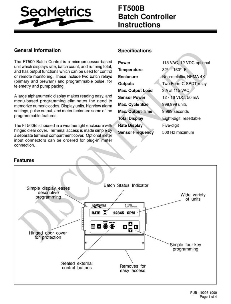
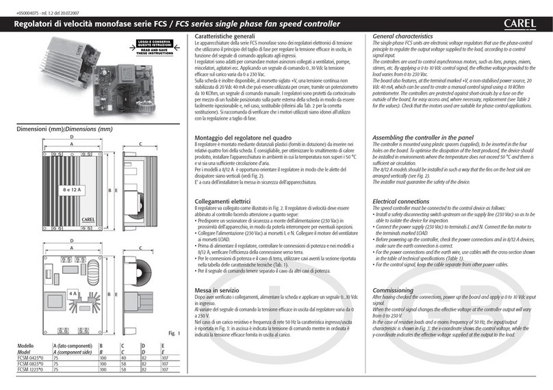
Seametrics FT520-84 User manual

LT-10830-A
Page 1 of 4
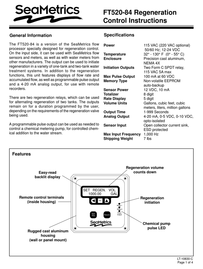
General Information Specifications
FT520-84 Regeneration
Control Instructions
Power 115/220 VAC, 50/60 Hz,
12-24 VDC
Temperature 32°- 130°F (0°- 55°C)
Enclosure Precision cast aluminum,
NEMA 4X
Initiation Outputs Two Form C SPDT relay,
115 VAC 5A max
Max Pulse Output 100 mA at 60 VDC
Memory Type Non-volatile EEPROM
auto-backup
Sensor Power 12 VDC, 10 mA
Totalizer 8 digit
Rate Display 5 digit
Volume Units Gallons, cubic feet, cubic
meters, liters, million gallons
Output Time 1-999 Seconds
Analog Output 4-20 mA, 0-10 VDC,
opto-isolated
Sensor Input Open collector current sink,
ESD protected
Max Input Frequency 1,000 Hz
Shipping Weight 7 lbs
Features
Easy-read
backlit display
Remote control terminals
(inside housing)
Rugged cast aluminum
housing
(wall or panel mount)
Chemical pump
pulse LED
Regeneration
initiation
Regeneration volume
counts down
The FT520-84 is a version of the SeaMetrics flow
processor specially designed for regeneration control.
On the input side, it can be used with SeaMetrics flow
sensors and meters, as well as contacting water meters
from other manufacturers. The output can be used to
initiate regeneration in a variety of one-tank and two-
tank water treatment systems. In addition to the
regenerationfunctions,thisunitfeatures displays offlow
rate and accumulated flow, as well as programmable
pulse output and a 4-20 mA analog output, for use with
remote recorders.
There are two regeneration relays, which can be used
for alternating regeneration of two tanks. The outputs
remain on for a duration programmed by the user,
dependingon therequirements ofthe regenerationvalve
being used.
Aprogrammable pulse outputcan be used asneeded to
control a chemical metering pump, for controlled chem-
ical addition to the water stream.
SET REGEN. VOL.
1000.00 GAL
ARCHIVED

Installation
Wall Mounting. Usingthe eightscrewsprovided,attach
the two foot brackets to the sides of the enclosure.Then
attachthe unit to anysecure surface byinserting screws
through the mounting holes in the foot brackets.
Panel Mounting. Follow the dimensions for “Panel
Cutout” to cut a hole in the panel. Slide the panel mount
gasket up from the bottom of the enclosure to its place
behind the panel mount flange. Insert the unit through
the panel cutout. Install the two panel mount brackets
on the sides of the unit using the eight screws provided.
Each bracket has one threaded center hole. Insert and
tighten one screw in each hole, until the flange is pulled
firmlyupagainst thepaneland thegasketis compressed.
ExposeTerminals. Removethefourscrewswhich hold
the front plate to its flange.Remove the front plate.The
display board is attached to this front plate. It is also
connected to the power board by a ribbon cable. For
convenience, this cable can be disconnected, or the
display board can be allowed to dangle while making
connections. Connections can be made inside the
enclosure, or the terminals can be unplugged for easier
access, by gently tugging on them.
Sensor Connection. Followthe “Connections”diagram
to connect either two or three wires from the flow meter
or flow sensor.
Regeneration Valve Connection. Connect the leads
which initiate the regeneration valve(s) to the terminals
marked Relay 1 and Relay 2. (See “Connections” dia-
gram.) If only one unit is being connected, use Relay 1.
(Relay 2 will operate only if “Alternate Relays” mode is
being used.)
Power Connection. Connect AC or DC power as
desired to the appropriate terminals. For safety, if using
AC power, be sure to connect the ground terminal
provided to a good earth ground.
2 of 4
Displays
Settings
Set Flow Rate. Use to select volume units. Use
to select the particular unit desired (gallons, liters, etc.).
Then use to switch to time units. Again, select the
one desired.
SetDecimal. Use toselect zero,one,ortwo decimal
places on the flow units.
Set K-Factor. The unit will not function properly until
this number is entered. It is simply the number of pulses
which the flow meter or flow sensor puts out per gallon
of liquid. It is marked on the Model/Serial tag of
SeaMetrics flow meters and flow sensor fittings. On
adjustableflow sensors, theK-factor mustbe taken from
the chart in the flow sensor instructions, based on pipe
size. Set the number with keys.The digit which
is underlined is the one being set. The moves one
digit to the left. The increases the digit. When the
appropriate number has been set, press again to
move on to the next menu item.
Caution: When the control is
powered up, relay or analog out-
puts may be present. If this
could be a hazard, wait to make
external connections until pro-
gramming is complete.
!
Replace the front panel, taking care to reconnect the
ribbon cable if it has been disconnected. When power
is switched on, the display should light up immediately
with meaningful letters or digits.
0.00 GPM
O.00 GAL
SETTINGS
OPERATION MODE
SET DECIMAL
SET
SET SET K-FACTOR
SET
SET
SET
SET
SET
SET
SET
SET REGEN. VOL.
1000.00 GAL
TO CLEAR TOTAL
PRESS UP & LEFT
SET 20mA RATE
0.00 GPM
return to
operation mode
Running
Totalizer
0.00 GPM
1.000
SET PULSE OUT
.00 GAL
SET REGEN. TIME
5 SEC'S
SET RELAY MODE
ALTERNATE RELAYS
SET GAL
MINUTE
FLOW
RATE SET GAL
MINUTE
FLOW
RATE
OR
0.00 GPM
O.00 GAL
T
OR
T = Total
Volume
counts down
ARCHIVED

3 of 4
Connections
Set Pulse Out. An output pulse is activated at the
selected volume intervals if this feature is in use.
Otherwise, it does not need to be set.
Set 20 mA Out. A 4-20 mA analog output is standard
on this unit. If a 4-20 mA current loop is connected, set
the flow rate, in the desired units, at which the peak 20
mA is desired.The controller will automatically scale the
4 mA output to zero flow.
Set Regeneration Volume. This is the volume (in the
units you have selected, typically gallons) at which the
relay energizes to initiate a regeneration cycle. Set to
the desired amount using the and keys.
Set Regeneration Time. This is the length of time, in
seconds that the relay remains energized to initiate
regeneration. Using the key, set for a bit over the
minimumtimerequired bytheregenerationvalve tobegin
a cycle.
Set Relay Mode. Choose between single relay (Relay
No.1) and dualrelay (AlternateRelays) operation, using
the key.Inalternate relaymode, thefirstregeneration
will use relay 1, and the next will use relay 2, and so on.
ClearTotal. This function resets the running total back
to zero. It is unrelated to the regeneration function, and
can be ignored unless it is needed. To reset to zero,
press and simultaneously, as instructed.
Operation
Choice of Displays. When allof the settings have been
entered, the next press of the Set key puts the unit in
operation. If a T appears at the left side of the display,
thevalues shown are flow rate andrunning total. If there
is no T, the values shown are flow rate and units
remaining until regeneration. The total increases with
flow, and the regeneration quantity counts down. Use
the key to choose the preferred display, usually
regeneration quantity.
RegenerationInitiation. Whenthe regenerationquantity
number first reaches 0, relay 1 energizes for the length
of time which has been set. The regeneration quantity
immediately resets to its setting and begins counting
down again. If alternating mode has been selected, the
nexttime itreaches 0, relay2 willenergize, andthe cycle
after that returns to relay 1.
Pulse 1
Alternate
low-voltage power 12-24 VDC
Pulse 2
Relay 2
Relay 1 NC
COM
NO
NC
NO
COM
Regeneration
Initiation
Line
Neutral
Ground
Resume
0-10 V
Sensor input
Analog
Outputs
4-20 mA
External Power
Internal Power
Start/Stop
–
+
–+
s1
+
–
s2
RESUME
COM
REGENERATION
Remote
Controls
Pulse Outputs
(for metering pumps)
Main
power fuse
250 mA DC Power fuse
1 Amp
Power
loop power
jumper
Ribbon connector
from display board
Meter
Ground
Power signal
RED
WHITE
BLACK
Dry contact
–
+
Relay Pulse
10 Amp
ARCHIVED

20419 80th Ave. So., Kent, WA 98032 USA
Phone: 253-872-0284 Fax: 253-872-0285
www.seametrics.com 1-800-975-8153
Connection for Alternating Tanks Panel cut-out dimensions
Alternating Tanks Application
!
Caution: Always disconnect
power to the unit before open-
ing the terminal cover. Do not
reconnect power until all con-
nections have been made and
the terminal cover has been replaced.
4 of 4
Anoutput canbemanuallyforcedat anytime bypressing
the Start/Stop key. The relay will energize for the set
time, and regeneration volume will return to its original
setting to begin counting down again.
Repair
Theonly field-repairablecomponent onthe FT520 isthe
fuse. If failure is due to a cause other than a blown fuse,
itis necessaryto replace theentire board stack. Contact
your distributor for information.
Fuses. The power supply and the analog output circuit
have fuse protection. The two fuses are on the board.
Replace the blown power fuse with a 250 mA, 5x20 mm
glass fuse, available from SeaMetrics or from Radio
Shack (or other electronic supply store). The DC power
fuse is a 1 Amp, 5x20 mm glass fuse.
6.00"
gasket
PANEL
CUTOUT
6.00"
Relay 1
Relay 2
NC
COM
NO
NC
NO
COM
Tank 1
Tank 2
TX Flow Sensor FT520-84
Tank 1 Tank 2
ARCHIVED
Other manuals for FT520-84
1
Other Seametrics Controllers manuals
