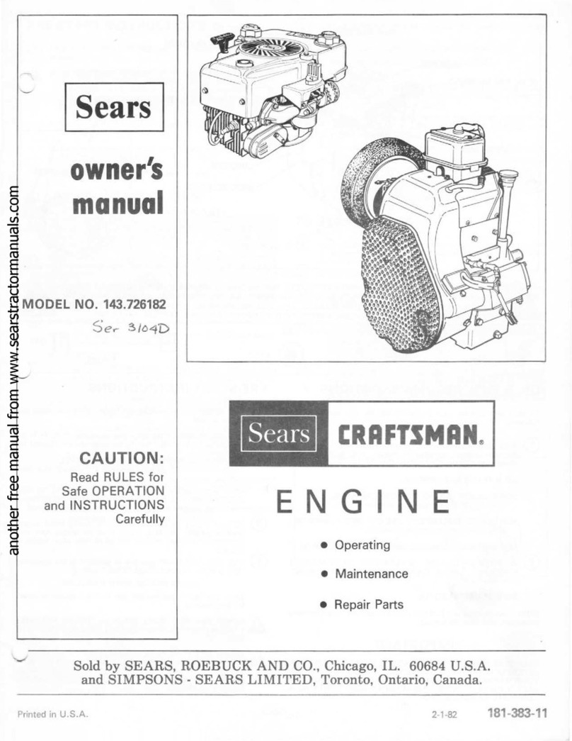
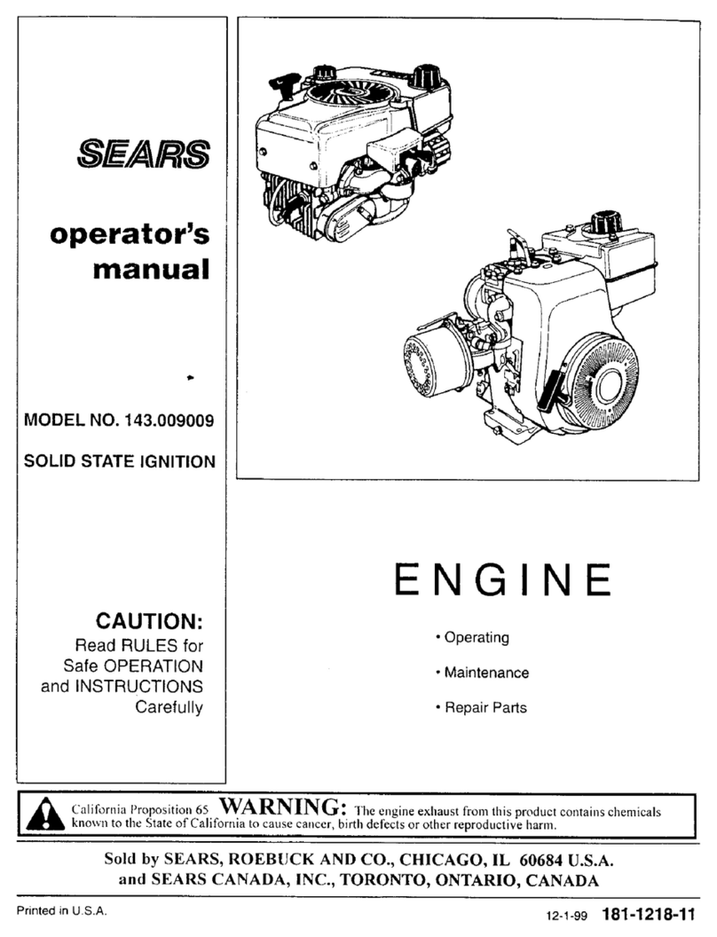
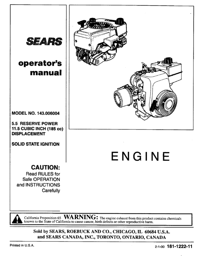
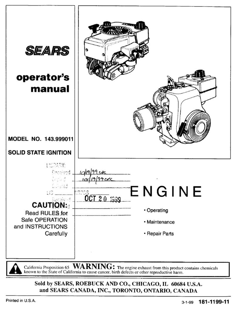
Sears 143.001302 User manual

SEARS
operator's
manual
MODEL NO. 143.001302
SOLID STATE IGNITION
CAUTION:
Read RULES for
Safe OPERATION
and INSTRUCTIONS
Carefully
ENGIN
•Operating
•Maintenance
• Repair Parts
] _ California Proposition65 WARNING: The engine exhaust from this product contains chemicals ]
known to the State of California to cause cancer, birth defects or other reproductive harm.
Sold by SEARS, ROEBUCK AND CO., CHICAGO, IL 60684 U.S.A.
and SEARS CANADA, INC., TORONTO, ONTARIO, CANADA
Printed in U.S.A. 10-1-00 181-1251-11

OIL FILL PLUG AND DIPSTICK \
'g,,_
|illlliPiilmlllllHrfl]
MODELAND
D,O.M. DECAL
SPARK PLUG WIRE
SPARK PLUG_ -- LEVERS & LINKAGE
OIL DRAIN PLUG
CARBURETOR
Figure 1
THIS SYMBOL POINTS OUT IMPORTANT SAFETY INSTRUCTIONS WHICH iF NOT FOLLOWED COULD ENDANGER THE PERSONAL An,
SAFETY AND/OR PROPERYT OF YOURSELF AND OTHERS. READ AND FOLLOW ALL INSTRUCTIONS IN THIS MANUAL AND ANY 4k
PROBIDEDWITHTHEEQUIPMENTONWHICHTHISENGINEISUSEDBEFOREATTEMPTINGTOOPERATEYOURCRAFTSMAN
ENGINE.
THESE SYMBOLS MAY APPEAR ON THE ENGINE:
FAST SLOW STOP
OFFI11FOL"
CHOKE
NOTE: Engines which are certified tocomply with California and U.S.
EPA emission regulations for SORE (Small Off Road Equipment), are
certified to operate on regular unleaded gasoline, and include the
following emission control systems: Engine Modification (EM), and
Three-way Catalyst (TWC) (if so equipped).
OIL & FUEL RECOMMENDATIONS
TO OPERATE ENGINE, YOU WILL NEED THE FOLLOWING:
(_) A CLEAN, HIGH QUALITY, DETERGENT OIL.
Be sure original container is marked:
A.P.I. service "SF"-"SJ".
FOR SUMMER (ABOVE 320F; OoC)USE SAE 30 OIL.
Using multigrade oil will increase oilconsumption.
FOR WINTER (BELOW 32°F; 0°C) USE SAE 5W30 OIL.
(SAE 10W is an acceptable substitute.)
DO NOT USE SAE lOW40 OIL.
OIL SUMP CAPACITY: 32 ounces (2 U.S. pints).
.94 liter
A FRESH, CLEAN, UNLEADED REGULAR, UNLEADED
PREMIUM, OR REFORMULATED AUTOMOTIVE
GASOLINE ONLY. DO NOT USE LEADED GASOLINE.
NOTE: DO NOT USE GASOLINE CONTAINING METHANOL (WOOD
ALCOHOL). Gasoline containing up to 10% ethanol or grain alcohol
("Gasohol"), or up to 15% MTBE (Methayl Tertiary Butyl Ether), may be
used but requires special care when engine is unused for extended periods.
See "STORAGE" instruction on Page 4.
NOTE: Use clean oil and fuel and store in approved, cJean covered
containers. Use clean fillfunnels.
Never use "stale" gasoline left over from last season or stored for long
pedods.
Page I
IMPORTANT
KEEP THIS MANUAL HANDY AT ALL TIMES FOR FUTURE
REFERENCE. READ IT CAREFULLY AND FAMILIARIZE
YOURSELF WITH THE OPERATING, MAINTENANCE AND
SAFETY INSTRUCTIONS. THIS MANUAL ALSO CONTAINS
A COMPLETE PARTS LISTING.
BEFORE STARTING
(_ READ ALL INSTRUCTIONS PROVIDED WITH THE
EQUIPMENT ON WHICH THIS ENGINE IS USED.
(_) CHECK OIL LEVEL:
CAUTION: NEVER RUN ENGINE UNLESS OIL LEVEL IS BETWEEN
"FULL" AND "ADD" MARKS ON DIPSTICK.
CHECK OIL LEVEL OFTEN DURING ENGINE BREAK-IN. NEVER RUN
ENGINE UNLESS OIL FILL PLUG IS TIGHTENED SECURELY INTO
OIL FILL HOLE,
A. POSmON EQUIPMENT SO ENGINE IS LEVEL.
8. Cleanareaaroundoilfillplug(seeFigurel).
C. Remove oil fill plug and dipstick.
D. Wipe dipstick clean, insert it into oil fill hole and tighten securely.
E. Remove oilfill plugand check oillevel. If level isnct upto"FULL" rnark
on dipstick, add recommended oil, until it is. POUR SLOWLY. Wipe
dipstick clean each time oil level is checked.
DO NOT FILL ABOVE "FULL" MARK ON DIPSTICK.
F. Replace oil fill plugand tighten securely.
TO ENSURE ADEQUATE OIL SUPPLY:
G, DISCONNECT SPARK PLUG WIRE FROM SPARK PLUG AND
KEEP IT AWAY FROM SPARK PLUG.
H. Crank engine a few times with starter
NOTE- DO NOT USE MOWER CUTTING BLADE OR ANY OTHER
ATTACHMENT ON POWER TAKE-OFF END OF CRANKSHAFT
TO CRANK ENGINE.
L Re-check oil level per instructions C, D, E and F.
J. Connect spark plug wire to spark plug.
See =MAINTENANCE" section for any future oil level and oil change
instructions (see Page 2).
181-1251-11

BEFORE STARTING (Continued)
r
A'_ THE ALUMINUM COMPONENTS OF YOUR NEW ENGINE HAVE BEEN
TREATED WITH A PRESERVATIVE INTENDED TO MAINTAIN THE
APPEARANCE OF THE ENGINE. THE PRESERVATIVE WILL CURE
DURING THE INITIAL USE OF THE ENGINE. A SMALL AMOUNT OF
SMOKE MAY BE PRESENT DURING THE INITIAL USE OF THE
PRODUCT AND SHOULD BE CONSIDERED NORMAL.
FILL FU EL TAN K withgasolineasspecifiedinthepreceding "OIL
& FUEL RECOMMENDATIONS," item 2.
NEVER MIX OIL WITH GASOLINE
Never use "stale" gasoline left over from last season or stored for long
periods.
r
_1 NEVER FILL FUEL TANK INDOORS. NEVER FILL FUEL TANK WHEN
ENGINE IS RUNNING OR HOT. DO NOT SMOKE WHEN FILLING FUEL
ITANK.
_i NEVER FILL FUEL TANK COMPLETELY. FILL TANK TO 1/2" BELOW
BOTTOM OF FILLER NECK TO PROVIDE SPACE FOR FUEL
EXPANSION. WIPE ANY FUEL SPILLAGE FROM ENGINE AND
EQUIPMENT BEFORE STARTING ENGINE.
_kANY LIQUEFIED PETROLEUM (LPG) OR NATURAL GAS FUEL
SYSTEM MUST BE LEAKPROOFAND MEETALLAPPLICABLE CODES
! AND REGULATIONS,
(_, CHECK THE FOLLOWING:
BE SURE EQUIPMENT IS IN NEUTRAL GEAR WITH CLU_
_k A. BELTS, CHAINS AND SAFETY SWITCHES DISENGAGEEL I
(FOLLOW EQUIPMENT MANUFACTURER S INSTRUCTIONS), I
T;ISRSHOUpLcDI;ILoANCE ANY SAFETY SWITCHES IN SAFE I
S. Be sure spark plug wire is attached to spark plug (see Figure 1)
C. BesureanyignitionswitchonengineorequipmentisinON, RUNor
START position.
STARTING
r
,_NEVER RUN ENGINE INDOORS OR IN ENCLOSED, POORLY
VENTILATED AREAS. ENGINE EXHAUST CONTAINS CARBON
MONOXIDE, AN ODORLESS AN DDEADLY GAS (CARBON MONOXIDE
ISALSO PRESENT IN ENGINE EXHAUST FROM LIQUID PETROLEUM
(LPG) AND NATURAL GAS FUEL SYSTEMS).
,_lb KEEP HANDS, FEET, HAIR AND LOOSE CLOTHING AWAY FROM
ANY MOVING PARTS ON ENGINE AND EQUIPMENT.
,_BE SURE AIR INTAKE SCREEN (see Fig. 1) IS SECURELY IN PLACE
TO AVOID CONTACT WITH MOVING PARTS.
L_li WARNING TEMPERATURE OF MUFFLER AND NEARBY AREAS MAY
EXCEED 150°F (65°C)` AVOID THESE AREAS.
NOTE: If engine is remotely controlled, see equipment manufacturer's
instructionsfor remote control positions which correspond to engine
control positions in Figure 2.
ELECTRIC STARTER 12 VOLT D.C.:
A. Move engine controllever (see Figure 2) orequipment controlto CHOKE
or START,
NOTE: IF RESTARTING A WARM ENGINE, AFTER A SHORT
SHUTDOWN, MOVE CONTROL TO"FAST"INSTEAD OF"CHOKE."
B. Press starter button or turn ignition switch key per equipment
manufacturer's instructions to crank engine until itfires.
C. When engine starts move controlto FAST and then to RUN RANGE.
D. Ifengine falters, move control to CHOKE, then to FAST and then to RUN
RANGE.
NOTE: Ifengine fires, butdoes notcontinue to run, move controlto FAST
and crank engine until itstarts.
E. If engine still does not start, move control to CHOKE and repeat
instructions Band C again.
STOPPING
_) Move equipment control or any ignition stop switch on engine to STOP or
OFF (see equipment manufacturer's instructions).
(_ AFTER ENGINE IS STOPPED:
A. ISCONNECT SPARK PLUG WIRE FROM SPARK PLUG AND
KEEP IT AWAY FROM SPARK PLUG.
,i
4. TURN IGNITION SWITCH KEY (IF SO EQUIPPED) TO "OFF"
POSITION AND REMOVE KEY FROM SWITCH. THIS WILL
IREDUCE THE POSSIBIU'rY OF UNAUTHORIZED STARTING OFENGINE WHILE EQUIPMENT IS NOT IN USE.
_li NEVER STORE ENGINE WITH FUEL IN TANK INDOORS OR IN
ENCLOSED, POORLY VENTILATED AREAS, WHERE FUEL
FUMES MAY REACH AN OPEN FLAME, SPARK OR PILOT LIGHT
AS ON A FURNACE, WATER HEATER, CLOTHES DRYER OR
OTHER GAS APPLIANCE,
MAINTENANCE I
WARNING: TEMPERATURE OF MUFFLER AND NEARBY
AREAS MAY EXCEED 150°F (65°C). AVOID THESE AREAS. J
1_ CHECK OIL LEVEL:
Check oil level every five (5) operating hours oreach time engine isused.
See "2 CHECK OIL LEVEL" in"BEFORE STARTING" on Page 1.
@CHANGE OIL:
Change oilafter firsttwo (2) operating hours and every 25 operating hours
thereafter, more often ifoperated in extremely dusty ordirty conditions.
, Chanqe oil while enqine isstillwarm from recent running.
4. DISCONNECT SPARK PLUG WIRE FROM SPARK PLUG AND
KEEP IT AWAY FROM SPARK PLUG.
B. Positionequiprnent so engine oil drain plug islowest point on engine.
C. Remove oil drain plug and oilfill plugto drain oil.
D. Replace oil drain plug and tighten securely.
E, Fill oil sump with recommended oil. See "OIL & FUEL
RECOMMENDATIONS" and =CHECK OIL LEVEL" on Page 1.
F. Replace oil fill plug and tighten securely.
G. Connect spark plug wire to spark plug.
CONTROLBRACKET
/
IDLE_ _FAST
"RUN"RANGE
CHOKE
CABLECLAMF
Figure 2
Page2181-1251-11

MAINTENANCE (Continued)
(_) AIR CLEANER:
IMPORTANT: NEVER RUN ENGINE WlTHOUTCOMPLETE AIR CLEANER
INSTALLED ON ENGINE.
A. TO SERVICE FILTER(S) (see Figure 3):
1. FOAM FILTER:
Clean and re-oil every three (3) months or every 25 operating hours.
Clean and re-oil daily if used inextremely dusty conditions.
a. Wash in water and detergent solution and squeeze (don't twist)
untilall dirt is removed.
b. Rinse thoroughly inclear water.
c. Wrap inaclean clothand squeeze (don'ttwist) untilcompletely dry.
d. Saturata with engine oil and squeeze (don't twist) to distdbuta oil
and remove excess oil.
2. PAPER OR FOAM/SCREEN FILTERS:
DO NOT A'rI'EMPT TO CLEAN OR OIL FILTER.
Replace once ayear orevery 100 operating hours, more often if used
in extremely dusty conditions.
Replacement filters are available at any nearby Sears Roebuck and
Co. (or Sears Canada, Inc.) Service Center.
B. TO REMOVE AND INSTALL FILTER(S):
1. Remove wing nutsand cover.
2. Slide FILTER Aoff FILTER B.
3. Inspect filter(s) for discolorationor dirtaccumulation. Ifeither ispresent,
service per preceding "TO SERVICE FILTER(S)" instructions.
4. Remove nuts and FILTER B. Discerd FILTER Band nuts (if service is
necessary).
5. Clean inside of cover and bodythoroughly.
6. Install new FILTER B and new nuts.Tighten nuts finger tight and then
tam one (1) more complete turn.
7. Slide foam filter over paper filter.
8. Install cover and wing nuts. Tighten wing nuts.
NUTS
-- FILTER A
(FOAM)
FILTER B
Figure 3
MAINTENANCE (Continued)
®SPARK PLUG (see Figure 4):
This spark ignition system meets all requirements of the Canadian
Interference-Causing Equipment Regulations. This engine complies with
allcurrentAustralian and New Zealand limitationsregardingelectromagnetic
interference. Check spark plug yearly or every 100 operating hours.
A. Clean area around spark plug.
B. Remove and inspect spark plug.
C. Replace spark plug if electrodes are pitted, burned or porcelain is
cracked. For replacement use Champion RN4C or equivalent.
NOTE: A resistor spark plug must be used for replacement.
D. Check electrode gap with wire feeler gauge and set gap at .030 if
necessary.
E. Install spark plug,tighten securely.
CTRODES
.030 GAP
'PORCELAIN
Figure4
(_) ALTERNATOR AND BATTERY (ifso equipped):
A. ALTERNATOR:
For electrical problems such as inoperative starter or discharged
battery, see your nearby Sears Roebuck and CO. (or Sears Canada,
Inc.)Service Center forfuse replacement (ifso equipped), maintenance
and repairs.
B. BATrERY:
1. Whenservicingbattery, alwaysconnectcablestobatteryexactly
as they were before removal (ground cable to battery negative [-
or neg.] post). If incorrectly connected, altemator won't charge
battery. If this happens, see your Sears Roebuck and Co. (or
Sears Canada, Inc.) Service Center.
2. Never expose engine igniti0n system to battery power. If battery
cable orany live wirecontacts ignitionsystem groundwire, engine
ignition system may be damaged.
3. Ifexternal battery charger is used, disconnect positive (+ or pus.)
cable from battery to prevent possible damage.
4. See battery manufacturer's instructions for service and storage.
(_) COOLING SYSTEM:
IMPORTANT: Frequently remove any grass clippings, dirt and debris from
cooling fins, air intake screen and levers and linkage (see Figurss 1and 5).
This will help ensure adequate cooling and correct engine speed.
AIR INTAKE SCREEN
Figure 5
@CHECK ENGINE AND EQUIPMENT OFTEN FOR LOOS_
NUTS, BOLTS AND ATTACHMENTS AND KEEP THES_
==, ITEMS TIGHTENED. J
Page3 181-1251-11

ADJUSTMENTS
DO NOT MAKE UNNECESSARY ADJUSTMENTS. FACTORY SETTINGS
ARE SATISFACTORY FOR MOST APPLICATIONS AND CONDITIONS. IF
ADJUSTMENTS ARE NEEDED, PROCEED AS FOLLOWS:
(_) CARBURETOR:
Ifyou think your carburetor needs adjusting, see your nearest SEARS,
ROEBUCK AND CO. (OR SEARS CANADA, INC.) SERVICE
CENTER. Engine performance should not be affected at altitudes up
to 7,000 feet. For operation at higher elevations, contact your nearest
SEARS, ROEBUCK AND CO. (OR SEARS CANADA, INC.) SERVICE
CENTER.
CONTROLBRACKET CONTROL LEVER - IN FAST POSITION
(HOLE IN LEVER IN LINE WITH NOTCH
REMOTE
CONTROL
:ABLE
CABLE CLAMP
CHOKE
RUN RANGE
Figure 6
(_) REMOTE CONTROL (see Figure6):
Forsatisfactory engine performance, engine and equipment controls must
be adjusted properly. To check engine control adjustments, proceed as
follows:
A. Set equipment control at FAST or HIGH SPEED and keep in this
position.
B. Loosen clamp screw so remote control cable can be moved in cable
clamp (donot remove cable clamp from control bracket or disconnect
remote control cable from engine control lever).
C. Move engine control lever into FAST and hold in this position.
D. Tightenclampscrewsecurelysocableclampwillholdcablecasingin
place when equipment control is used. The engine should now run at
the desired speed when equipment control is set at FAST, and should
choke engine when in CHOKE.
Ifadditional controladjustments are necessary, contact you rnearby Sears
Roebuck and Co. (or Sears Canada, Inc.) Service Center.
(_ ENGINE SPEED:
NEVER TAMPER WITH ENGINE GOVERNOR WHICH IS FACTORY I
SET FOR PROPER ENGINE SPEED. OVERSPEEDING ENGINE ABOVE J
FACTORY HIGH SPEED SETTING CAN BE DANGEROUS.
ENO,NE OVERNEOSPEEDW,"VOOENGNE
STORAGE
NEVER STORE ENGINE WITH FUEL IN TANK INDOORS OR I1_
I_ ENCLOSED, POORLY VENTILATED AREAS, WHERE FUEL FUME_
MAY REACH AN OPEN FLAME, SPARK OR PILOT LIGHT AS ON/_
FURNACE, WATER HEATER, CLOTHES DRYER OR OTHER GAS_
APPLIANCE.
IF ENGINE IS TO BE UNUSED FOR 30 DAYS OR MORE, PREPARE AS
FOLLOWS:
(_) DRAIN FUEL SYSTEM:
Remove all gasoline from carburetor and fueltankto prevent gum deposits
from forming on these parts and causing possible malfunction of engine.
DRAIN FUEL INTO APPROVED CONTAINER OUTDOORS, AWA_
FROM OPEN FLAME. BE SURE ENGINE IS COOL. DO NOT SMOKE_
Run engine until fuel tank is empty and engine stops due to lack of fuel.
@
NOTE: Fuel stabilizer (such as ULTRA-FRESH TM) is an acceptable
alternative inminimizing the formation ofgum deposits during storage. Add
stabilizer to gasoline in fuel tank or storage container. Always follow mix
ratio found on stabilizer container. Run engine at least 10 minutes after
adding stabilizer to allow itto reach carburetor.
CHANGE OIL:
Change oil if it has not been changed in the last three (3) months. See
"CHANGE OIL" instructions in "MAINTENANCE" section.
(_ OIL CYLINDER BORE:
A. Remove spark plug. Squirt one (1) oz. (30 ml) of clean engine oil into
spark plug hole.
B. Crank engine over, slowly, several times.
_IL AVOID SPRAY FROM SPARK PLUG HOLE WHEN CRANKIN_J
ENGINE OVER SLOWLY.
D. Replace spark plug.
@CLEAN ENGINE:
Clean engine by removing any clippings, dirt, or chaff from exterior of
engine,
GENERAL
Just as your automobile needs professional mechanical maintenance from time
to time, so does your Craftsman engine. Replacement of the spark plug and air
cleaner is made necessary by NORMAL use. professional Air-Cooled Engine
Service is as close as your nearest Sears Roebuck and Co. (or Sears Canada,
Inc.) Service Center.
Ayearly check-up or tune_up by Sears isa good idea to avoid breakdowns or
delay.., do it at the end of the season, then you're ready for the next. We even
prepare itfor storage for you.
Page4181-1251-11

TROUBLESHOOTING
THE FOLLOWING MAY HELP AVOID A DELAY IN YOUR WORK OR
SAVE THE EXPENSE OF A SERVICE CALL.
ENGINE FALLS TO START OR STARTS WITH DIFFICULTY
CAUSE
Controls not in start position.
Spark plug wire disconnected from spark plug.
Spark plug fouled.
Spark plug porcelain cracked.
Insufficient fuel.
Water or dirt in fuel,
Improper carburetor adjustment
REMEDY
Move ENGINE CONTROL or equipment control to "HI" or
START postion. See "STARTING" instructions in this
manual.
Connect SPARK PLUG WIRE to SPARK PLUG.
Remove SPARK PLUG and clean it. See "SPARK
PLUG" instructions in "MAINTENANCE" section in this
manual.
Install new spark plug.
Fill FUEL TANK per "BEFORE STARTING" instructions.
Drain FUEL TANK and re-fillwith clean, fresh gasoline.
See "BEFORE STARTING" instructions in this manual.
Adjust carburetor (ifapplicable). See "ADJUSTMENTS"
section in this manual.
ENGINE LACKS POWER
CAUSE
Dirty air cleaner.
Improper carburetor adjustment.
Lack of lubricaiton.
REMEDY
Replace or clean air cleaner per "AIR CLEANER"
instructions in "MAINTENANCE" section in this manual.
Adjust carburetor (if applicable). See "ADJUSTMENTS"
section in this manual.
Fill oil sump to proper level. See "BEFORE STARTING"
instructions section in this manual.
ENGINE MISSES UNDER LOAD
CAUSE
Spark plug fouled.
Sparkplugporcelaincracked.
Impropersparkpluggap.
Improper carburetor adjustment
REMEDY
Remove SPARK PLUG and clean it. See "SPARK
PLUG" instructions in "MAINTENANCE" section in this
manual.
Install new SPARK PLUG.
Regap SPARK PLUG electrodes. See "SPARK PLUG"
instructions in "MAINTENANCE" section in this manual.
Adjust carburetor (if applicable). See "ADJUSTMENTS"
section in this manual.
Page5 181-1251-11

SEARS, ROEBUCK AND CO.
Federal and California Emission Control Systems Limited Warranty
Small Off-Road Engines
CALIFORNIA & US EPA EMISSION CONTROL
WARRANTY STATEMENT
The U. S. Environmental Protection Agency ("EPA"), the California Air Resources
Board CCARB") and Sears, Roebuck and Co. are pleased to explain the Federal
and California Emission Control Systems Warranty on your new small off-road
engine In California, new 1995 and later small off-road engines must be
designed, built and equipped to meet the State's stringent anti-smog standards
In other states, new 1997 and later model year engines must be designed, built
and equipped, at the time of sale, to meet the US EPA regulations for small non-
road engines. Sears, Roebuck and Co. will warrant the emission control system
on your small off-road engine for the periods of time listed below, provided there
has been no abuse, neglect, unapproved modification, or improper maintenance
of your small off-road engine
Your emission control system may inctude parts such as the carburetor, ignition
system and exhaust system. A!5o included may be the compression release
system and other emission-related assemblies.
Where a warrantabJe condition exists, Sears, Roebuck and Co. will repair your
small off-road engine at no cost to you for diagnosis, parts and labor
MANUFACTURER'S EMISSION CONTROL SYSTEM
WARRANTY COVERAGE
Emission control systems on 1995 and later model year California small off-road
engines are warranted for two years as hereinafter noted. In other states, 1997
at_d later model year engines are also warranted for two years, If, during such
warranty period, any emission-related part on your engine is detective in materials
or workmanship, the part will be repaired or replaced by Sears, Roebuck and Co.
OWNER'S WARRANTY RESPONSIBILITIES
AS the small off-road engine owner, you are responsible for the performance of
the required maintenarlce listed in your Owner's Manual, but Sears, Roebuck and
CO will not deny warranty soleiy due to the lack of receipts or for your failure to
provide written evidence of the performance of all scheduled maintenance
AS the small off-road engine owner, you should, however, be aware that Sears,
Roebuck and Co. may deny you warranty coverage if your small off-road engine or
a part thereof has failed due to abuse, neglect, improper maintenance or
unapproved modifications
You are responsible for presenting your small off-road engine to a Sears,
Roebuck and Co, Authorized Service Outlet as soon as a problem exists. The
warranty repairs should be completed in a reasonable amount of time, not to
exceed 30 days
Warranty service can be arranged by contacting either a Sears, Roebuck and Co.
Authorized Service Outlet, or by contacting Sears, Roebuck and Co. at
1-800-473-7247
IMPORTANT NOTE
This warranty statement explains your rights and obligations under the Emission
Control System Warranty ("ECS Warranty") which is provided to you by Sears,
Roebuck and Co. pursuant to California law. See also the Sears, Roebuck and
CO. Limited Warranties for Sears, Roebuck and Co. which is enclosed therewith
on a separate sheet and also is provided to you by Sears, Roebuck and CO The
ECS Warranty applies only to the emission control system of your new engine.
To the extent that there is any conflict in terms between the ECS Warranty and the
Sears, Roebuck and Co. Warranty, the ECS Warranty shall apply except in any
circumstances in which the Sear& Roebuck and CO. Warranty may provide a
longer warranty period. Both the ECS Warranty and the Sears, Roebuck and Co,
Warranty describe important rights and obligations with respect to your new
engine
Warranty sel%dce can only be performed by a Sears, Roebuck and Co. Authorized
Service Outlet. At the time of requesting warranty service, evidence must be
presented of the date of sale to the original purchaser. The purchaser shall pay
any charges for making service calls and/or for transporting the prroducts to and
from the place where the inspection and/or warranty work is performed. The
purchaser shall be responsible for any dama_ge or _oss incurred in connection with
the transportation of any engine or any part(s) thereof submitted for inspection
and/or warranty work
If you have any questions regarding your warranty rights and responsibilities, you
should contact Sears, Roebuck and Co. at 1-800-473-7247.
EMISSION CONTROL SYSTEM WARRANTY
Emission Control System Warranty ("ECS Warranty") for 1995 and later model
year California small off-road engines (for other states, 1997 and later model year
engines):
A, APPLICABILITY: This warranty shall apply to 1995 and later model year
California small off-road engines (for other states, 1997 and later mode/year
engines) The ECS Warranty Period shall begin on the date the new engine or
equipment is delivered to its original end-use purchaser, and shall continue for
24 consecutive months thereafter
B. GENERAL EMISSIONS WARRANTY COVERAGE: Sears, Roebuck and Co
warrants to the original, end-use purchaser of the new engine or equipment and to
each subsequent purchaser that each of its small off-road engines is:
1 Designed, built and equipped so as Io conform with all applicable
regulations adopted by the Air Resources Board pursuant to its authority in
Chapters 1 and 2, Part 5, [3iv[sion 26 of the Health and Safety Code, and
2 Free from defects in materials and workmanship which, at any time during
the ECS Warranty Period, will cause a warranted emissions-related part to
fail to be identica/in all material respects to the part as described in the
engine manufacturer's application for certification
C The ECS Warranty only pertains to emissions-related parts on your engine, as
follows:
1.
2.
Any warranted, emissions-related parts which are not scheduled for
replacement as required maintenance in the Owner's Manual shall be
warranted for the ECS Warranty Period. If any such part fails during the
ECS Warranty Period, it shall be repaired or replaced by Sears, Roebuck
and Co. according to Subsection 4 below. Any such part repaired or
replaced under the ECS Warranty shall be warranted for any remainder of
the ECS Warranty Period.
Any warranted, emissions-related part which is scheduled only for regular
inspection as specified in the Owner's Manual shall be warranted for the
ECS Warranty Period. A statement in such written instructions to the
effect of "repair or replace as necessary", shall not reduce the ECS
Warranty Period. Any such part repaired or replaced under the ECS
Warranty shall be warranted for the remainder of the ECS Warranty
Period.
3.
4.
Any warranted, emissions-related part which is scheduled for replacement
as required maintenance in the Owner's Manual, shall be warranted for the
period of time prior to the first scheduled replacement point for that part. If
the part fails prior to the first scheduled replacement, the part shall be
repaired or replaced by Sears, Roebuck and Co. according to Subsection 4
be_ow. Any such emissions-related part repaired or replaced under the
ECS Warranty, shall be warranted for the remainder of the ECS Warranty
Period prior to the first scheduled replacement point for such emissions-
related part.
Repair or replacement of any warranted, emissions-related part under this
ECS Warranty shall be performed at no charge to the owner at aSears,
Roebuck and Co Authorized Service Outlet.
The owner shall not be charged for diagnostic labor which leads to the
determination that a part covered by the ECS Warranty is in fact defective,
provided that such diagnostic work is performed at a Sears, Roebuck and
CO. Authorized Service Outlet.
6. Sears, Roebuck and Co. shall be liable for damages to other original
engine components or approved modifications proximatelly caused by a
failure under warranty of an emission-related part coveredby the ECS
Warranty
7. Throughout the ECS Warranty Period, Sears, Roebuck and Co. shall
maintain a supply of warranted emission-related parts sufficient to meet
the expected demand for such emission-related parts.
8. Any Sears, Roebuck and Co, authorized and approved emission-re{ated
replacement part may be used in the performance of any ECS Warranty
maintenance or repair and will be provided without charge to the owner.
Such use shall not reduce Sears, Roebuck and Co. ECS Warranty
obligations
Unapproved add-on or modified parts may not be used to modify or repair
a Sears, Roebuck and Co. engine, Such use voids this ECS Warranty and
shall be sufficient grounds for disallowing an ECS Warranty claim. Sears,
Roebuck and Co, shall not be liable hereunder for failures of any warranted
parts of a Sears, Roebuck and Co. engine caused by the use of such an
unapproved add-on or modified part.
EMISSION-RELATED PARTS INCLUDE THE FOLLOWING:
1. Carburetor Assembly and its Internal Components
a) Fuel filter
b) Carburetor gaskets
¢) Intake pipe
2. Air Cleaner Assembly
a) Air filter element
3. Ignition System, inc}uding:
a) Spark plug
b) Ignition module
c) Flywheel assembly
4, Catalytic Muffler (if so equipped)
a) Muffler gasket (if so equipped)
b) Exhaust manifold (if so equipped)
5. Crankcase Breather Assembly and its Components
a) Sreather connection tube
Sears, Roebuck and Co., Hoffman Estates, IL 60179 U.S.A.
Page 6 181-1251-11

CRAFTSMAN 4-CYCLE ENGINE MODEL:143.001302
101.
263
261
170 171
212A 204
1B6A
Page7 181-1251-11

CRAFTSMAN 4-CYCLE ENGINE MODEL:143.001302
Ref+
No.
1
2
14
15
16
17
18
19
20
25
26
28
30
31
35
36
37
38
40
40
40
41
41
41
42
42
42
43
45
47
48
50
51
52
60
62
63
65
66
68
69
70
72
75
80
81
82
83
84
86
88
89
90
92
101
lO2
Part
No.
35943A
27652
28277
35324
36284A
29916
651028
35945
35319
36460
650561
30322
35336B
35327
29826
29918
29216
29642
35776A
35777A
35778A
35773A
35774A
35775A
35779
35780
35781
35772
36925
651O33
35313
35939
35315A
31356
35316A
650760
28545
650128
30063
33356
*35317
35711A
31927
35319
35712
35479A
35321
35322
29193
650833
31707A
32589
611177
650880
650881
35135A
610118
651024
Ref. Part
Part Name No. No.
Cylinder (Incl. 2 & 20) 103
Dowel Pin 110
Washer 110A
Governor Rod 119
Governor Lever (Incl. 212A) 120
Governor Lever Clamp 123
Screw, T-15, 8-32 x 3/8.... 124
Extension Spring 125
Oil Seal 125
Blower Housing Baffle 126
Screw, 1/4-20 x 19/32" 127
Lock Nut, 8-32 128
Crankshaft 130
Counterbalance Gear 135
Screw, 10-32 x 3/4" 150
Lock Washer 151
Lock Nut, 10-32 153
Retaining Ring 154
Piston, Pin & Ring Set (Std.) 155
Piston, Pin & Ring Set (.010" OS) 156
Piston, Pin & Ring Set (.020" OS) 157
Piston & Pin Ass'y. (Std.) (Incl. 43) 158
Piston & Pin Ass'y. (.010" OS) (Incl. 159
43) 160
Piston & Pin Ass'y. (.020" OS) (Incl. 161
43) 169
Ring Set (Std.) 170
Ring Set (.010" OS) 171
Ring Set (.020" OS) 172
Piston Pin Retaining Ring 173
Connecting Rod Ass'y. (Incl. 47) 174
Connecting Rod Bolt 180
Valve Lifter 181
Camshaft (MCR) 182
Counterbalance Weight 184
Oil Pump Ass'y. 185
Blower Housing Extension 186
Screw, 8-32 x 3/8" 186A
Grommet 200
Screw, 10-24 x 1/2" 203
Screw, T-30, 1/4-20 x 1/2" 204
Ground Terminal 209
Mounting Flange Gasket 210
Mounting Flange (Incl. 72, 75 & 80) 211
Oil Drain Plug 212A
Oil Seal 223
Governor Shaft 224
Washer 234
Governor Gear Ass'y. 237
Governor Spool 238
Retaining Ring 239
Screw, 1/4-20 x 1-3/16" 240
Spacer 245
Flywheel Key
Flywheel (W/Ring Gear)
Lock Washer
Flywheel Nut
Solid State Ignition
Spark Plug Cover
Solid State Mounting Stud
651007
35183
36225
*35946
35948
35288
65O738
35308
35433
35309
650691
650690
650946
34645
33507
33508
35949
650945
35950
650890
650947
35951
*35952
35953A
30063
"27896A
28423
28424
28425
35350
650128
37101
30200
650517
*33263
35955
36285
35957
35956
36482
651019
650902
27793
28942
36288
650971
*35958
650825
35286
650875
*33629
35960
35403
Part Name
I Screw, T-15, 10-24 x 15/16"
Ground Wire
Ground Wire
Cy nder Head Gasket
Cylinder Head (Incl. 270A)
Intake Pipe Brace
Screw, 1/4-20 x 5/8"
Exhaust Valve (Std.)
Exhaust Valve (1/32" OS)
Intake Valve (Std.)
Washer
Belleville Washer
Screw, 5/16-18 x 2-45/64"
Resistor Spark Plug (RN4C)
Valve Spring
Valve Spring Keeper
Push Rod Guide
Rocker Arm Stud
Rocker Arm
Lock Washer
Lock Nut, 5/16-24
Push Rod
Rocker Arm Cover Gasket
Rocker Arm Housing
Screw, T-30, 1/4-20 x 1/2"
Valve Cover Gasket
Breather Body
Breather Element
Valve Cover
Breather Tube
Screw, 10-24 x 1/2"
Blower Rousing Extension
Screw, 10-24 x 9/16"
Screw, T-30, 1/4-20 x 27/32"
Carburetor To Intake Pipe Gasket
Intake Pipe
Governor Link
Choke Link
Control Bracket (Incl. 203 & 204)
Compression Spring
Screw, 6-32 x 41/64"
Screw, 10-32 x 7/16"
Conduit Clip
Screw, 10-32 x 3/8"
Bushing
Screw, T-30, 5/16-18 x 7/8"
Intake Pipe Gasket
Nut & Lockwasher, 1/4-20
Air Cleaner Adapter
Screw, 10-32 x 5-1/4"
Carburetor Gasket
Air Cleaner Body (Incl. 239)
Air Cleaner Filter (Incl. 234)
*Indicates Parts included in
Gasket Set, Ref. No. 400.
Page 8 181-1251-11

CRAFTSMAN 4-CYCLE ENGINE MODEL:143.001302
Ref. Pad
No. No.
245A
250
251
260
261
262
263
264
265
270A
290
292
296
305
307
3O8
308A
310
314
315
319
32O
322
322A
35404
35961
650886
35964
651031
29747B
35963
650273
35959
35829A
29774
26460
34279B
35574
35499
33997
35437
35576
650873
611176
650735
611175A
610921
611188
Ref. Pad
Pad Name No. No.
Air Cleaner Filter 322B
Air Cleaner Cover 323
Wing Nut, 1/4-20 323A
Blower Housing 323B
Screw, 1/4-20 x 9/16" 324
Screw, T-40, 5/16-24 x 21/32" 326
Trim Ring 330
Screw, 5/16-18 x 17/32"
Cylinder Head Cover 337
Exhaust Port Liner 347
Fuel Line (8.25") 363
Fuel Line Clamp 380
Fuel Filter (Incl. 292) 393
Oil Fill Tube 394
"O" Ring 400
Fill Tube Clip 900
Fill Tube Clip
Dipstick 900
Screw, 1/4-20 x 3/4"
Alternator Coil (5 Amp) (Incl. 322 &
323B)
Screw, 10-24 x 3/8"
Regulator
Connector
Connector Body
611117
611140
611118
610922
33177
36210
36419
36407
650949
34148
640164
35962
650948
35947
Part Name
Connector Body
Terminal
Terminal
Terminal
Terminal
Blower Housing Plug
Wire Harness (Incl. 322,322A,
322B, 323, 323A & 323B)
Deflector
Screw, 10-24 x 9/16"
Spring
Carburetor (Incl. 184)
Cup & Screen
Washer
Gasket Set (Incl. Items Marked *)
Replacement Engine 752328A,
order from 71-999
Replacement Short Block 752321,
order from 71-999
*Indicates Parts Included in
Gasket Set, Ref. No. 400.
RPM High 3200 to 3400
RPM Low 1950 to 2250
CARBURETOR NO. 640164
/
V
--37
44 /
Ref. Part
No. No. PaN Name
640164
1 632649
A 6286
632685
*631184
5 *631183
6 632517
7 *650506
10 632472
11 632473
12 *631184
13 *631183
14 632429A
16 632527
17 651026
18 630766
20 640027
20A 640053
25 631867
27 *631024
28 632019
29 *631028
30 *631021
31 631022
36 640113
37 *632547
40 640163
44 2711gA
47 *630748
48 *631027
60 632760
Carburetor (Incl. 184 of Engine Parts
List)
Throttle Shaft & Lever Assembly
Throttle Link Bushing
Throttle Return Spring
Dust Seal Washer
Dust Seal (Throttle)
Throttle Shutter
Shutter Screw
Choke Shaft & Lever Assembly
' Choke Return Spring
Dust Seal Washer
Dust Seal (Choke)
Choke Shutter
Fuel Fitting
Throttle Crack Screw/Idle Speed Screw
Tension Spring
Idle Restrictor Screw
Idle Restrictor Screw Cap
Float Bowl
Float Shaft
Float
Float Bowl "O" Ring
Inlet Needle, Seat, & Clip (Incl. 31)
Spring Clip
Main Nozzle Tube
Main Nozzle Tube "O" Ring
High Speed Bowl Nut
Bowl Nut Washer
Welch Plug, Idle Mixture Well
Welch Plug, Atmospheric Vent
Repair Kit (Incl. Items Marked *)
Page 9 181-1251-11

Page 10 181-1251-11

SEARS
operator's
manual
MODEL NO. 143.001302
SOLID STATE IGNITION
CAUTION:
Read RULES for
Safe OPERATION
and INSTRUCTIONS
Carefully
How to ORDER Repair Parts
The Model Number can be found on a decal on the blower
housing (See Figure 1). Always mention the Model Number
when requesting service or repair parts for your Craftsman
Engine.
All parts listed herein may be ordered from any SEARS,
ROEBUCK AND CO. or SEARS CANADA, INC. retail or
catalog store. If the parts you need are not stocked locally, your
order will be electronically transmitted to a Sears Repair Parts
Distribution Center for expedited handling.
WHEN ORDERING REPAIR PARTS, ALWAYS GIVE THE
FOLLOWING INFORMATION AS SHOWN IN THIS LIST.
1. The PART NUMBER
2. The PART DESCRIPTION
3. The MODEL NUMBER
4. The NAME OF ITEM - ENGINE
"Your Sears merchandise has added value when you consider that Sears has
service units nationwide staffed with Sears trained technicians.., professional
technicians specifically trained on Sears products, having the parts, tools and
equipment to insure that we meet our pledge to you ... we service what we sell."
Sold by SEARS, ROEBUCK AND CO., CHICAGO, IL 60684 U.S.A.
and SEARS CANADA, INC., TORONTO, ONTARIO, CANADA
181-1251-!1
Table of contents
Other Sears Engine manuals

Sears
Sears 143.994006 User manual

Sears
Sears 143.004012 User manual

Sears
Sears 143.995008 User manual

Sears
Sears Craftsman 143.726182 User manual

Sears
Sears 143.999 User manual

Sears
Sears 143.999011 User manual

Sears
Sears 143.998003 User manual

Sears
Sears 143.996706 User manual

Sears
Sears 143.009009 User manual

Sears
Sears 143.004010 User manual