PRE-START INSTRUCTIONS tcontinuedl
®
"
CHECK
THE
FOLLOWING before attempting to start your
engine:
A.
BE
;
WRE
EOUIPMENT
~
:
iS.
.
iN
:
:
Ne
·
urt~AL
i
G~AR
WITH
.
¢(QTCHIS
.s,
BELtS
}
CHAINS,
··
ere
:,
blS!NGAGEO
,
{fOLLOW
EOUif:iM£Nt ·
MANUFACTURER'S
IN
·
STRUCTIONS.} THIS
SHOULD
PLACE.
ANV
SAFETY
SWITCHES
IN
SAfE
STARTING POSITION.
B.
Be
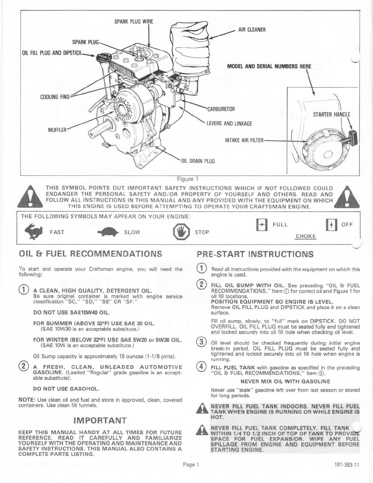
sure SPARK
PLUG
WIRE is attached to SPARK PLUG.
(see
Figure
1)
C.
Be
sure
any ignition switch on engine
or
equipment
is
in ON,
RUN
or START position.
D.
Be
sure
FUEL
FILL
CAP air vent is open.
STARTING INSTRUCTIONS
h NEVER. RUN ENGlNE
lNDOORS
OR
IN
ENCLOSED,
..
POOf\tYVEN'f'ILATED
AREAS. ENGINE EXHAUST CON-
TAINS
CARBON
MONOXIDE,
AN
ODORl.ESS
AND
DEADLY GAS. . ..
h KEEP
HANDS,
FEET,
HAIR
AND
LOOSE CLOTHING
..
AWAY
FROM
ANY
MOV!NG
PARTS
ON
.ENGINE
AND
EQUIPMENT.
h
WARNING
-TEMPERATURE
OF
MUFFlER
AND
NEAR-
..
BY
AREAS
MAY
EXCEED
1SOOF
(OO'Cl.
AVOID
THESE
AREAs.
..
.
G)
COLD ENGINE START (Engine has not
been
run recently).
A. Move remote control on equipment to
CHOKE
(see
equip-
ment manufacturers instructions).
B.
START
ENGINE
1.
Grasp
STARTER
HANDLE
(see
Figure
2)
and pull rope
out, slowly, until
it
pulls harder dueto engine compres-
sion. Let rope rewind slowly.
2.
Pull rope with arapid continuous full arm stroke. Let rope
rewind SLOWLY. Don't let
STARTER
HANDLE snap
back against starter.
3.
Repeat
preceding Instructions 1 and 2 until engine fires
and when engine starts, move equipment control to
FAST position.
Ifenginefalters, move equipment control
to
CHOKE
untill
engine runs smoothly and then
to
FAST.
NOTE: If engine fires, but fails to start, move equipment
control to FAST and repeat preceding Instructions 1 and
2 until engine starts.
If
engine fires, butfails to start again, repeat preceding
In
-
structions
1,
2 and 3 until engine starts.
®
WARM
ENGINE START (Engine still warm from recent
running).
NOTE -Warm engine may start without choking.
A. Move remote control on equipment to FAST.
B.
START
ENGINE
1.
Grasp
STARTER
HANDLE
(see
Figure
2)
and pull rope
out, slowly, until it pulls harder due to engine compres-
sion. Let rope rewind slowly.
2.
Pull rope with arapid continuous full
arm
stroke. Let rope
rewind SLOWLY. Don't let
STARTER
HANDLE
snap
back against starter.
3.
Repeat
preceding Instructions 1 and 2 until engine starts.
Ifenginefalters, move equipment control
to
CHOKE
untill
engine runs smoothly and then
to
FAST.
NOTE: If engine fails to start after a reasonable number
of
starting attempts, follow preceding "
CD
COLD
ENGINE
START" instructions.
TO STOP ENGINE
G)
®
Move remote control
on
equipment or any ignition stop switch
on engine to
STOP
or
OFF
position
(see
equipment manu-
facturer's instructions).
AFTER ENGINE IS STOPPED:
h
A.
DISCONNECT SPARK PLUG WIRE FROM
SPARK
..
PLUG
AND
PLACE
IT
WHERE
IT
CAN
NOT
CONTACT
SPARK PLUG. . ·
h B. TURN
IGNITION
SWITCH KEY
If
SO
EQUIPPED. TO
..
''
OFF" POSITION
AND
REMOVE KEY FROM SWITCH.
THIS
WILL
REDUCE
THE
POSSIBILITY
OF
UNAUTHORIZED STARTING OF ENGINE
WHILE
EQUIPMENTfS
NOT
IN
USE.
h C. NEVER STORE ENGINE WJTH FUEL IN
TANK
IN~
..
DOORS OR
IN
ENClOSED, POORLY VENTILATED
ENCLOSURES,WHERE
~UEL
fUMES
MAY
REACH
AN
OPEN FLAME,
SPARK
OR
PILOT LIGHT
AS
ONA
FURNACE, WATER HEATER. CLOTHES DRYeR, ETC.
Figure 2
Page2
181-383-11
another free manual from www.searstractormanuals.com