DIAGRAM OF THE CONSOLE
V
35
30
25
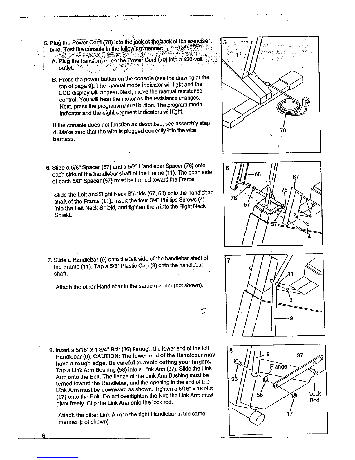
20
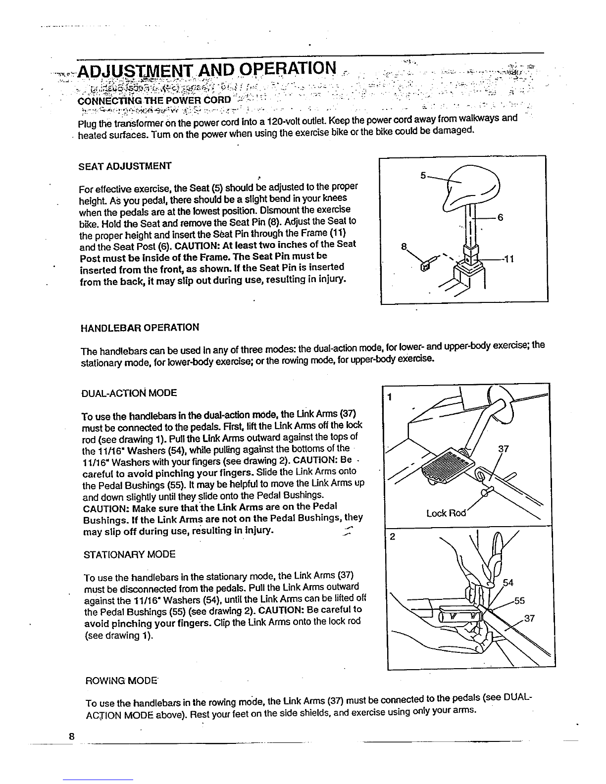
15
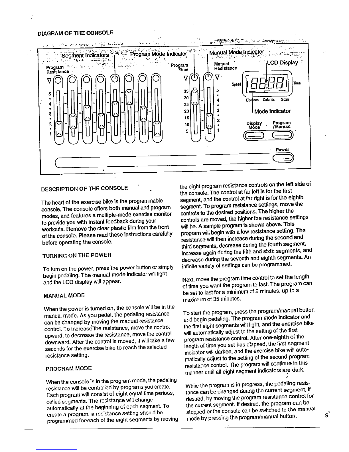
•Power
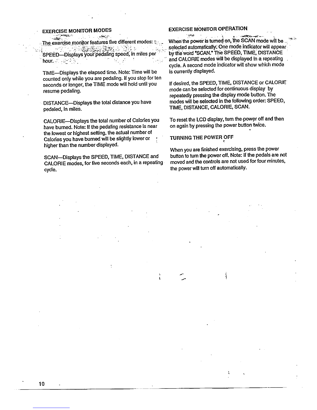
i
DESCRiPTiON OF THE CONSOLE
The heart of the exercise bike is the programmable
console. The console offers both manual and progrem
modes, and features a multiple-mode exercise monitor
to provide you with Instant feedback during your
workouts. Remove the clear plastic film from the front
of the console. Please read these instructionscarefully
before operating the console.
TURNING ON THE POWER
To turnon the power, press the power button or simply
begin pedaling. The manual mode indicator willlight
and the LCD display will appear.
MANUAL MODE
When the power is turned on, the console willbe in the
manual mode. As you pedal, the pedaling resistance
can be changed by moving the manual resistance
control. To increase'lhe resistance, move the control
upward; to decrease the resistance, move the control
downward. After the control is moved, it willlake a few
seconds for the exercise bike to reach the selected
resistance setting.
PROGRAM MODE
When the console is in the program mode, the pedaling
resistance willbe controlled by programs you create.
Each program will consist of eight equal time periods,
called segments. The resistance will change
automatically at the beginning of each segment. To
create aprogram, a resistance setting should be
programmed for.each of the eight segments by moving
the eight program resistance controls on the left side of
the console. The control at far left is for the first
segment, and the control at far right is for the eighth
Segment. To program resistance settings, move the
controlsto the desired positions.The higher the
controlsare moved, the higher the resistance settings
willbe. A sample program is shown above. This
program WIUbegin with a low resistance setting. The
resistance willthen increase dudng the second and
third segments, decrease during the fourth segment,
increase again during the fifth and sixth segments, and
decrease during lhe seventh and eighth segments. An
infinitevariety of settings can be programmed.
Next, move the program time control to set the length
of time you want the program to last. The program can
be set to last for aminimum of 5 minutes, up to a
maximum of 35 minutes.
To start the program, press the program/manual button
and begin pedaling. The program mode indicator and
the first eight segments will light,and the exercise bike
will automatically adjust to the setting of the first
program resistance control. Alter one-eighth of the
length of time you set has elapsed, the first segment
indicatorwill darken, and the exercise bike will auto-
matically adjust to the setting of the second program
resistance control. The program will continue in this
manner untilall eight segment indicators are dark.
While the program is in progress, the pedaling resis-
tance can be changed during the current segment, if
desired, by moving the program resistance control for
the current segment. If desired, the program can be
stopped or the console can be switched to the manual
mode by pressing the program/manual button. 9


 Service manual")