manuals.online logo
Brands
  1. Home
  2. •
  3. Brands
  4. •
  5. Sears
  6. •
  7. Tiller
  8. •
  9. Sears Craftsman 917.293550 User manual

Sears Craftsman 917.293550 User manual

Other Sears Tiller manuals

Sears Craftsman 944.621554 User manual

Sears

Sears Craftsman 944.621554 User manual

Sears 944.621534 User manual

Sears

Sears 944.621534 User manual

Sears CRAFTSMAN 247.298760 User manual

Sears

Sears CRAFTSMAN 247.298760 User manual

Sears Craftsman 917.299852 User manual

Sears

Sears Craftsman 917.299852 User manual

Sears Craftsman 944.629660 User manual

Sears

Sears Craftsman 944.629660 User manual

Sears Craftsman 842.252440 User manual

Sears

Sears Craftsman 842.252440 User manual

Sears Craftsman 944.629541 User manual

Sears

Sears Craftsman 944.629541 User manual

Sears Craftsman 842.252440 User manual

Sears

Sears Craftsman 842.252440 User manual

Sears CRAFTSMAN 944.629665 User manual

Sears

Sears CRAFTSMAN 944.629665 User manual

Sears CRAFTSMAN 944.625930 User manual

Sears

Sears CRAFTSMAN 944.625930 User manual

Sears Craftsman 944.621563 User manual

Sears

Sears Craftsman 944.621563 User manual

Sears 247.29773 User manual

Sears

Sears 247.29773 User manual

Sears Craftsman 944.621531 User manual

Sears

Sears Craftsman 944.621531 User manual

Sears Craftsman 944.624930 User manual

Sears

Sears Craftsman 944.624930 User manual

Sears CRAFTSMAN 944.621574 User manual

Sears

Sears CRAFTSMAN 944.621574 User manual

Sears CRAFTSMAN 944.621204 User manual

Sears

Sears CRAFTSMAN 944.621204 User manual

Sears CRAFTSMAN 917.293401 User manual

Sears

Sears CRAFTSMAN 917.293401 User manual

Popular Tiller manuals by other brands

WIL-RICH 2500 Operator's manual

WIL-RICH

WIL-RICH 2500 Operator's manual

MTD 410R parts list

MTD

MTD 410R parts list

Viking HB 685 instruction manual

Viking

Viking HB 685 instruction manual

SMASH TLG415 instruction manual

SMASH

SMASH TLG415 instruction manual

FarmBoy FB-IC-209P user manual

FarmBoy

FarmBoy FB-IC-209P user manual

Craftsman 247.29931 Operator's manual

Craftsman

Craftsman 247.29931 Operator's manual

MTD FRT Series Operator's manual

MTD

MTD FRT Series Operator's manual

Craftsman 917.298353 owner's manual

Craftsman

Craftsman 917.298353 owner's manual

Troy-Bilt Colt FT Operator's manual

Troy-Bilt

Troy-Bilt Colt FT Operator's manual

MTD OHV Series Original operating instructions

MTD

MTD OHV Series Original operating instructions

YAT YT5601-01 Assembly, Use, Maintenance Manual

YAT

YAT YT5601-01 Assembly, Use, Maintenance Manual

Craftsman 917.296010 owner's manual

Craftsman

Craftsman 917.296010 owner's manual

Scheppach MTP560 Translation from the original instruction manual

Scheppach

Scheppach MTP560 Translation from the original instruction manual

GARDEN WAY 12194 owner's manual

GARDEN WAY

GARDEN WAY 12194 owner's manual

Classen STAND-AER SA-25 Operator's manual and parts list

Classen

Classen STAND-AER SA-25 Operator's manual and parts list

Altrad ATIKA BH 1400 N Original instructions, safety instructions, spare parts

Altrad

Altrad ATIKA BH 1400 N Original instructions, safety instructions, spare parts

DR PILOT 2 Safety & Operating Instructions

DR

DR PILOT 2 Safety & Operating Instructions

AL-KO TL 1820 Instructions for use

AL-KO

AL-KO TL 1820 Instructions for use

manuals.online logo
manuals.online logoBrands
  • About & Mission
  • Contact us
  • Privacy Policy
  • Terms and Conditions

Copyright 2025 Manuals.Online. All Rights Reserved.

MODEL NO.
917.293550
Caution:
Read and follow
all Safety Rules
and instructions
Before Operating
This Equipment
®
5.0 HP
14 INCH TINE WBDTH
REAR TmNETILLER WUTH
COUNTER ROTATING TiN
,Assembly
, Operation
®Customer Responsibilities
,Service and Adjustments
®Repair Parts
............................... i1,,,111i,, i1,,11,,111,,,111
Sears, Roebuck and Co., Hoffman Estates, IL 60179 U.S.A.
All manuals and user guides at all-guides.com
all-guides.com
SAFETY RULES
Safe Operation Practices for Walk-Behind Powered Rotary Tillers
TRAINING
o Read the Owner's Manual carefuNy. Be thorougNy
familiar with the controls and the proper use of the
equipment: Know how to stop the unit and disengage
the controls quickly_
- Never al!ow children to operate the equipment, Never
allow adults to operate the equipment without proper
instruction.
o Keep the area of operation clear of all persons, particu-
larly small children, and pets°
PREPARATION
. Thoroughly inspectthe area where the equipment isto
be used and remove all foreign objects.
. Disengage all ctutches and shift into neutral before
starting the engine (motor).
=Do not operate the equipment without wearing ad-
equate outer' garment& Wear footwear that will im-
prove footing on slippery surfaces.
o Handle fuel with care; it is highly flammable.
-Use an approved fuel containerv
=Never add fuei to a running engine or hot engine.
o Fill fuel tank outdoors with extreme care Never fill fuel
tank indoors.
,, Replace gasoline cap securely and clean up spiIled
fuel before restarting..
o Use extension cords and receptacles as specified by
the manufacturer for all units with electric drive motors
or electric starting motors.,
o Never attempt to make any adjustmertts while the
engine (motor) is running (except where specifically
recommended by manufacturer)
OPERATION
o Do not put hands or feet near or under rotating parts.
.Exercise extreme caution when operating on or cross-
ing grave! drives, walks, or roads Stay alert for hidden
hazards or'traffic. Do not carry passengers.
. After stdking a foreign object, stop the engine (motor),
remove the wire from the spark plug, thoroughly in-
spect the tiller for any damage, and repair the damage
before restarting and operating the tiller.
- Exercise caution to avoid s_ipping or falling_
* If the unit should start to vibrate abnormally, stop the
engine (motor) and check immediately for' the cause
Vibration is generally awarning of troubte.
oStop the engine (motor) when leaving the operating
position.
,, Take art possible precautions when leavir_g the ma-
chine unattended. Disengage the tines, shift into
neutral, and stop the engine,
. Before cleaning, repairing, or inspecting, shut off the
engine and make certain all moving parts have stopped
Disconnect the spark plug wire, and keep the wire
away from the plug to prevent accidental starting.
Disconnect the cord on electric motors
- Do not run the engine indoors; exhaust fumes are
dangerous_
,, Never operate the tiller without proper guards, plates,
or other safety protective devices in place.
o Keep children and pets away.
°Do not overload the machine capacity by attempting to
till too deep at too fast a rate
o Never' operate the machine at high speeds on slippery
surfaces. Look behind and use care when backing°
° Never atlow bystanders near the unit,
o Use only attachments and accessories approved by
the manufacturer of the tiller (such as wheel weights,
counterweights, cabs, and the like).
o Never operate the tiller without good visibility or light.
-Be careful when tilling in hard ground° The tines may
catch in the ground and propel the titler forward. If this
occurs, let go of the handlebars and do not restrain the
machine..
MAINTENANCE AND STORAGE
.Keep machine, attachments, and accessories in safe
working condition.
o Check shear pins, engine mounting bolts and other
be ts at frequent interva s for proper tightness to be
sure the equipment is in safe working condition.
• Never store the machine with fuel in the fuel tank inside
a building where ignition sources are present, such as
hot water and space heaters, clothes dryers, and the
like, Allow the engine to cool before storing in any
enciosure
. Always refer to the operator's guide instructions for
important details if the tiller is to be stored for an
extended period.
- IMPORTANT-
CAUTIONS, 1MPORTANTS, AND NOTES ARE A MEANS
OF ATTRACTING ATTENTION TO IMPORTANT OR
CRITICAL _NFORMATION iN THIS MANUAL.
IMPORTANT: USED TO ALERT YOU THAT THERE ISA
POSSIBILITY OF DAMAGING THIS EQUIPMENT.
NOTE: Gives essential information that will aid you to
better understand, incorporate, or execute a particular set
of instructions
................... i,,,u, i,m, i,, ,00,,,,
Look for this symbol to point out im-
portant safety precautions, It means
CAUTION!!! BECOME ALERT[t! YOUR
SAFETY IS INVOLVED.
i,i ........
CAUTION: Always disconnect spark
plug wire and place wire where it can-
not contact spark plug in order to pre-
vent accidental starting when setting
up, transporting, adjusting or making
repairs, ................LJI,-
WARNING
The engine exhaust from this product con-
tains chemicals known to the State of Califor-
nia to cause cancer, birth defects, or other
reproductive harm.
All manuals and user guides at all-guides.com
CONGRATULATIONS on your purchase of a Sears Tiller.
It has been designed, engineered and manufactured to
give you the best possible dependability and performance.
Should you experience any problems you cannot easily
remedy, please contact your nearest authorized Sears
Service CentedDepartmento They have competent, well-
trained technicians and the proper tools to service or repair
this unit.
Please read and retain this manual° The instructions will
enable you to assemble and maintain your tiller properly.
Always observe the "SAFETY RULES".
MODEL
NUMBER 917.293550
SERIAL
NUMBER
DATE OF
PURCHASE
THE MODEL AND SERIAL NUMBERS WILL BE
FOUND ON THE MODEL PLATE ATTACHED TO
THE TOP OF THE TRANSMISSION°
YOU SHOULD RECORD BOTH SERIAL NUMBER
AND DATE OF PURCHASE AND KEEP IN A SAFE
PLACE FOR FUTURE REFERENCE..
PRODUCT SPECIFICATIONS
HORSEPOWER: 5.,0HP
DISPLACEMENT; 12 57 cur in, (206cc)
GASOLINE CAPACITY: 3 Quarts
Unleaded Regular
OIL (APFSF/SG): SAE 30 (Above 32°F)
(CAPACITY: 20 oz) SAE 5W-30 (Below 32°F)
SPARK PLUG : Champion
(GAP: ..030") RJ19LM
MAINTENANCE AGREEIV]ENT
A Sears Maintenance Agreement is available on this prod-
uct. Contact your nearest Sears store for details.
CUSTOMER RESPONSIBILITIES
,Read and observe the safety rules..
,Follow a regular schedule in maintaining, caring for and
using your tiller
° Follow the instructions under the "Customer
Responsibilities" and "Storage" sections of this Owner's
Manual.
IMPORTANT: THISUNITIS EQUIPPED WITH AN INTERNAL COMBUSTION ENGINE AND SHOULD NOT BE USED ON
OR NEAR ANY UNIMPROVED FOREST-COVERED, BRUSH-COVERED OR GRASS COVERED LAND UNLESS THE
ENGINE'S EXHAUST SYSTEM IS EQUIPPED WITH A SPARK ARRESTER MEETING APPLICABLE LOCAL OR STATE
LAWS (IF ANY) IF A SPARK ARRESTER IS USED, IT SHOULD BE MAINTAINED IN EFFECTIVE WORKING ORDER BY
THE OPERATOR,
tN THE STATE OF CALIFORNIA THE ABOVE IS REQUIRED BY LAW (SECTION 4442 OF THE CALIFORNIA PUBLIC
RESOURCES CODE), OTHER STATES MAY HAVE SIMILAR LAWS. FEDERALL:AWS APPLY ON FEDERAL LANDS,
SEE YOUR SEARS AUTHORIZED SERVICE CENTER FOR SPARK ARRESTER REFER TO THE REPAIR PARTS
SECTION OF THIS MANUAL FOR PART NUMBER
LIMITED ONE YEAR WARRANTY ON CRAFTSMAN TILLER
For one year from date of purchase, when this Craftsman Tiller is maintained, lubricated, and tuned up according to
the operating and maintenance instructionsin the owner's manual, Sears will repair free of charge any defect in
material or workmanship.
This Warranty does not cover:
, Expendable items which become worn during normal use, such as tines, spark plugs, air cleaners and belts.
- Repairs necessary because of operator abuse or negligence, including bent crankshafts and the failure to
maintain the equipment according to the instructions contained in the owner's manual
• If this Craftsman Tiller is used for commercial or rental purposes, this Warranty applies for only 30 days from the
date of purchase°
WARRANTY SERVICE IS AVAILABLE BY RETURNING THE CRAFTSMAN TILLER TO THE NEAREST SEARS
SERVICE CENTER/DEPARTMENT IN THE UNITED STATES. THIS WARRANTY APPLIES ONLY WHILE THIS
PRODUCT iS IN USE IN THE UNITED STATES.
This Warranty gives you specific legal rights, and you may also have other rights which vary from state to state
SEARS, ROEBUCK AND CO.., D/817WA, HOFFMAN ESTATES, IL 60179
All manuals and user guides at all-guides.com
ii iil i,.lll ,', ................................... It-
"FABLE OF CONTENTS
i i , , i,i, i, Hi i,i imll i, i, i_!l_,1,,i., ,i ..... i, H _L
SAFETY RULES ............................................................ 2
CUSTOMER RESPONSIBILITIES ...................... 3,14-16
PRODUCT SPECIFICATIONS ...................................... 3
WARRANTY .................................................................. 3
ACCESSORIES ............................................................. 5
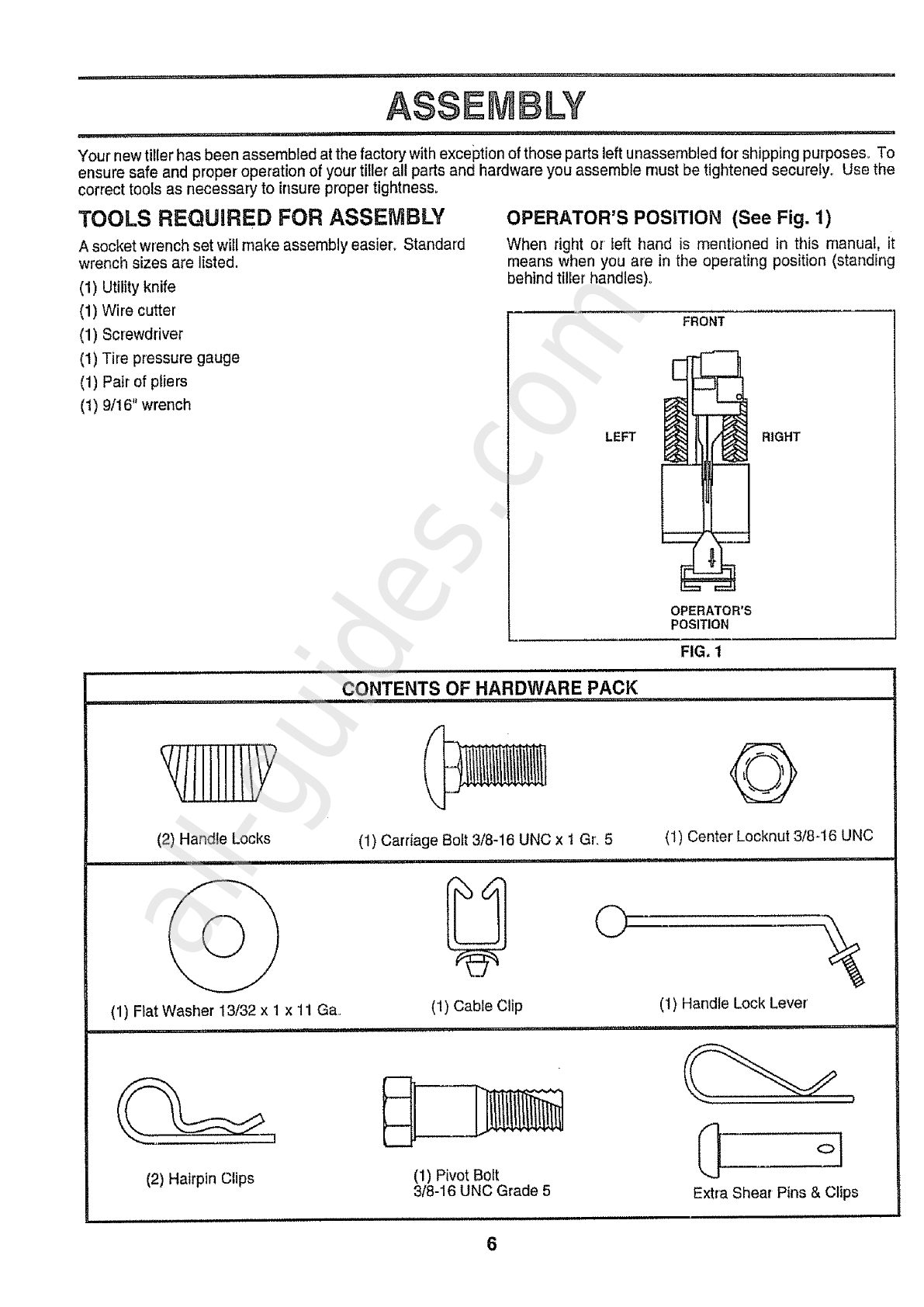
ASSEMBLY ............................................................... 6-8
OPERATION ............................................................ 9-13
MAINTENANCE SCHEDULE ..................................... 14
SERVICE & ADJUSTMENTS ................................. t6-19
STORAGE .................................................................... 20
TROUBLESHOOTING ................................................. 21
REPAIR PARTS=TILLER ....................................... 22-28
REPAIR PARTS-ENGINE ....................................... 29-33
SERVICE/PARTS ORDERING ............... BACK COVER
UNDEX
A
Accessories ..............................................5
Adjustments:
Carburetor ......................................19
Depth Stake .................................10
Handle Height ............................ 16
Side Shields ..................................11
Throttle ........................................ 1g
Tines ..................................................18
V-Belt (Ground Drive) ................17
Wheels .........................................13
Air Cleaner ...................................................15
B
Belt:Belt Guard .....................................17
Repair Parts ...................................23
V-Bett (Ground Drive) ................17
Cooling System .......................................15
Controls:
Choke ....................................................g
Throttle ....................................................9
Drive (Tines) ....................................9
Cultivating ....................................... 13
Customer Responsibilities:
Air Cleaner _...................................15
Cooling System ..............................15
Finish .......................................... 16
Maintenance Schedule ..............14
Muffler'. ............................................16
Oi! Change ..........................................15
Spark Plug ..................................16
Tines .....................................................18
Transmission ..................................16
V-Bett (Ground Drive) ................17
D
Depth Stake:
Adjustment ..................................!0
Repair Parts .............................. 26
E
Engine:
Air Cleaner. .....................................15
Cooling Systen'l ................................15
Fuel Type .....................................1t
Engine (cont'd)
Lubrication ........................................15
Oil Level ...........................................11
Oil Type ....................................11,t5
Spark Plug .....................................16
Starting ...........................................12
Stopping .........................................10
Storage .............................................20
Winter Operation ..........................15
F
FueI:
Filling Tank ...................................11
Storage ........................................20
Type ...................................................11
Finish:
Maintenance ...............................16
H
Handle:
Height Adjustment .....................16
Repair Parts ...................................22
L
Lubrication:
Lubrication Chart .................... 14
Engine .................................................15
M
Muffler:
Maintenance .......................................16
Spark Attester ...................................3
O
Oil: Level .................................................11
Type ..............................................11,!5
Operation:
Cultivating ........................................13
Fill Fuel Tank ................._................11
Starting Engine ...........................12
Stopping Tines & Engine ...........10
Tilling .........................................10
Tilling Hints .............................. 12
Tine Operation ............................10
Transporting Tiller. ......................11
Winter Operation ...........................15
4
R
Repair Parts:
Titler. ................................................22-28
Engine ...............................................29-33
Rules for Safe Operation ........................2
Service & Adjustments:
Carburetor .....................................19
Handle Height ..................................16
Side Shields ...................................11
Throttle ...........................................................19
Tines..........................................................18
V-Belt (Ground Drive) .............. 17
Wheels ...............................................13,16
Service:
Repair Parts .................................22-33
Service Record ..............................14
Shear Pins:
Operation ..........................................12
Repair Parts ....................................27
Spark Plug:
Gap ..........................................................3
Maintenance .......................................16
Storage:
Fuel System ......................................20
Tiller...................................................20
T
Tilling.................................................10,12
"Tines:
Arrangement/Replacement ...... 18
Operation ..............................................10
Repair Parts ....................................27
Shear Pins ...................................12
Transmission:
Maintenance ....................................16
Repair Parts ......................................25
Troubleshooting..........................................21
Transporting ...............................................t 1
W
Warranty ......................................................3
Wheels:
Adjustment .........................................13
Removal ..............................................16
Repair Parts .................................24
All manuals and user guides at all-guides.com
These accessories were available when the tiller was purchased. They are also available at most Sears Retail outlets
and Service Centers. Most Sears Stores can order repair parts for you when you provide the model number of your
tiller.
ENGINE
i i ,ill,
SPARK PLUG
..... i....
i
MUFFLER AIR FILTER GAS CAN sTABiLIZER_ENGINE OIL
,N,=,,,,i
TILLER PERFORMANCE
FURROW OPENER
, ,,,,,,,,,,,,,,
TILLER MAINTENANCE
_:._... ....
BELT TINES SHEAR PIN HAIRPIN CLIP
5
All manuals and user guides at all-guides.com
ASSEMBLY
.......... I ...... t,l,,,,l,,,,,,t,,ll,t,,,, ! ....................... t,,, ,tt .............................. t
Your new tiller has been assembled at the factory with exception of those parts left unassembled for shipping purposes_ To
ensure safe and proper operation of your tiller all parts and hardware you assemble must be tightened securetyo Use the
correct tools as necessary to insure proper tightness.
TOOLS REQUIRED FOR ASSEMBLY
A socket wrench set will make assembly easier° Standard
wrench sizes are listed.
(1) Utility knife
(1) Wire cutter
(1) Screwdriver
(1) Tire pressure gauge
(1) Pair of pliers
(1) 9/16" wrench
OPERATOR'S POSITION (See Fig. 1)
When right or left hand is mentioned in this manual, it
means when you are in the operating position (standing
behind tiller handles)..
FRONT
OPERATOR'S
POSITION
LEFT
FIG, 1
,, ,numn,l.i
CONTENTS OF HARDWARE PACK
RIGHT
(2) Handle Locks
(1) Flat Washer 13/32 x 1 x 11 Ga.
nl i ii i,i n,n,l,,,
(1) Carriage Boft 3/8-16 UNC x I Gr. 5
©
(1) Cable Clip
lu,, i,,,
Q
(1) Center Locknut 3t8-16 UNC
ii
(1) Handle Lock Lever'
(2) Hairpin Clips (1) Pivot Bolt
3/8-16 UNC Grade 5 Extra Shear Pins & Clips
6
All manuals and user guides at all-guides.com
all-guides.com
u l ',,,,,,....... ,i,,, i i,,11,
LY
ii i, i .... ,H,,,,I,, iH i ,
UNPACKING CARTON (See Fig. 2) ° Grasp handle assemblyo Holdin"up"position, Besure
handle lock remains in gearcase notch° Slide handle
! ._ CAUTION: Be careful of exp0sedq assembly into position,,
_ staples when handling or disposing of
ca.oningr.ate,ial, R
IMPORTANT; WHEN UNPACKING AND ASSEMBLING
TILLER, BE CAREFUL NOT TO STRETCH OR KINK
CABLES°
o While holding handle assembly, cut cable ties securing
handle assembty to top frame,, Let handle assembly
rest on tiller°
• Remove top frame of carton,,
• Slowly ease handle assembly up and place on top of
carton,
•Cut down right hand front and right hand rear corners
of carton, lay side carton wall down.
= Remove packing material from handle assembly.
= Separate shift rod from handle assembly.
SHIFT ROD
HANDLE
ASSEMBLY
FIG. 2
INSTALL HANDLE (See Figs. 3, 4, and 5)
. insert one handle lock (with teeth facing outward) in
gearcase notch, (Apply grease on smooth side of
handle lock to aid in keeping lock in place until handle
assembly is lowered into position°)
VIEWED FROM Roll.SIDE OF TILLER
DLE ASSEMBLY
GEARCASE
NOTCH HANDLE
LOCK
"%%,
HANDLE ASSEMBLY
"UP" POSITION
FIG. 4
• Rotate handle assembly down° insert rear carriage bolt
first, with head of bolt on Loll. side of tiller and loosely
assemble locknut (See Fig. 5).
-Insert pivot bolt in front part of plate and tighten.
o Cut down remaining corners of carton and lay panels
fiat°
• Lower the handle assembly. Tighten nut on carriage
bolt so handle moves with some resistance° This will
allow for easier adjustment°
o Place flat washer on threaded end of handle lock lever.
= Insert handle t0ck lever through handJe base and
gearcase. Screw in handle lock lever just enough to
hold lever in place,
.insert second handle lock (with teeth inward) inthe slot
of the handle base (just inside of washer)_
o Raise handle assembly to highest position and se-
curely tighten handle lock lever by rotating clockwise°
Leaving handle assembly in highest position will make
it easier to connect shift rod.
GEARCASE HANDLE
LOCK
REAR FLAT
CARRIAGE SLOT WASHER
BOLT r
_HANDLE
LOCK
LEVER
HANDLE _"
BASE PIVOT
LOCKNUT BOLT
FIG. 3 FIG. 5
All manuals and user guides at all-guides.com
' r, , ,,i .......... ___ i,,i,,,i ............. i...... , i,, i1,1,,
ASSEMBLY
........ ,...... ii...................................... i1,,,,,i,i.... ,...... i ,, ii!l
CONNECT SHIFT ROD (See Fig. 6)
°insert end of shift rod farthest from bend into hote of
shift [ever indicator.
°Insert hairpin clip through hole of shift rod to secure_
oinsert other end of shift rod into hote in shift Lever.
°Insert second hairpin ciip through hole of shift rod.
ATTACH THIS END
TO SHIFT LEVER
INDICATOR
A3"TACH THIS
END TO SHIFT
\
SHIFT ROD
SHIFT HAIRPIN SHIFT
LEVER
INDICATOR
SHIFT
HAIRPIN CLIP
SHIFT ROD
REMOVE TILLER FROM CRATE
,, Adjust handle assemby to lowest position, Be sure lock
lever is tightened securely,
= Make sure shift Iever indicator'is in "N" (neutral) posi-
tion (See Fig. 6)
oTilt tiller forward by Liftinghandle,, Separate cardboard
cover from leveling shield_
o Rotate tiLLerhandle to the right and pull tiller out of
carton.
HANDLE
COLUMN
CABLES
3ABLE CLIP
FIG. 7
INSERT CABLE CLIP (See Fig. 7)
o Insert plastic cable clip into hole on the back of handle
column, Push cables into clip_
CHECK TIRE PRESSURE
The tires on your unit were overinftated at the factory for
shipping purposes. Correct and equal tire pressure is
important for best tilling performance,
o Reduce tire pressure to 20 PSL
HANDLE HEIGHT
= Handle height may be adjusted to better suit operator°
(See "TO ADJUST HANDLE HEIGHT" in the Service
and Adjustments section of this manual),,
FIG. 6
8
All manuals and user guides at all-guides.com
I'MII""I'I"'"II'III'I' '' ' I I"11"'"""1 ' '1..... I I "1'1'"'1 ........... I
OPERAT O
II ........ i,,i,, i, i,,,11,,,,,111 , ,, , i1,1,11 I ...... i, ,, ,, ..... ...... I,
KNOW YOUR TILLER
READ THIS OWNER'S MANUAL AND SAFETY RULES BEFORE OPERATING YOUR TILLER.
Compare the illustrations with your tiller to familiarize yourself with the location of various controls and adjustments, Save
this manual for future reference.
i, ,,i,,, ,,,,..................... ,........ i"' '.......... ,,,,,,,,,, ....... i....
These symbols may appear on your Tiller or in literature Supplied wiih the produc ." Learn and understand their
meaning.
TILLING FORWARD NEUTRAL REVERSE CAUTION ENGINE ENGINE
OR WARNING ON OFF FAST SLOW STOP O
CHOKE FUEL OIL
................... """'' "" i..=,,,i,,=- ,,. i,,,,,11, ¸ ,
DRIVE
CONTROL THROTTLE
BAR CONTROL
SHIFT LEVER
SHIFT LEVER
INDICATOR RECOIL
STARTER
HANDLE
CHOKE CONTROL
DEPTH STAKE _O
LEVELING
SHIELD
OUTER
SIDE
SHIELD
FIG. 8
MEETS ANS! SAFETY REQUIREMENTS
Our tillers conform to the safety standards of the American National Standards institute,,
DRIVE CONTROL BAR - Used to engage tines,.
DEPTH STAKE - Controls depth at which tiIfer will dig.
LEVELING SHIELD -Levels tilled soil
OUTER SIDE SHIELD - Adjustable to protect small plants
from being buried.
THROTTLE CONTROL - Used to control engine speed_
SHIFT LEVER - Used to shift transmission gears.
SHIFT LEVER INDICATOR - Shows which gear the
transmission is ino
RECOIL STARTER HANDLE - Used to start the engine.
CHOKE CONTROL - Used when starting a cold engine.
9
All manuals and user guides at all-guides.com
i,, ,i, , OPERATION
,, i, n. ,i,,, i lu ........................ , ,,,,,,,,, ,,,,, Jl,t
inn ,i,,,,, ............
,i u, m, urn, ,
The operation of any tiller can result in foreign objects thrown into the eyes, which can
result in severe eye damage. Always wear safety glasses or eye shields before starting
your tiller and while tilling. We recommend a wide vision safety mask over the spectacles
or standard safety glasses.
HOW TO USE YOUR TILLER
Knew how to operate all controls before adding fuel and
oil or attempting to start engine.
STOPPING (See Fig, 9)
TINES AND DRIVE
o Release drive control bar to stop movement.,
• Move shift lever to "N" (neutral) position.
ENGINE
. Move throttle control to "STOP" position_
° Never use choke to stop engine.
DRIVE CONTROL BAR
"ENGAGED" I°OSIT]ON THROTTLE
SHIFT
/
DRIVE CONTROL BAR
"D_SENGAGED" POSITION
FIG. 9
TINE OPERATION - WITH WHEEL DRIVE
•Afways release drive control bar before moving shift
lever into another position
o Tine movement is achieved by moving shift Iever to"T"
(till) position and engaging drive control bar.
FORWARD -WHEELS ONLY/TINES STOPPED
o Release drive control bar and move shift lever' indicator
to"F" (forward) position, Engage drive control bar and
tiller will move forwa[do
REVERSE - WHEELS ONLY/TINES STOPPED
o DO NOT STAND DIRECTLY BEHIND TILLER°
o Release the drive control bar.
o Move throttle control to "SLOW" position_
o Move shift lever indicator to "R" (reverse) position.
o Hold drive control bat' against the handle to start tiller
movement,
DEPTH STAKE (See Fig. 10)
The depth stake can be raised or lowered to allow you more
versatile tilling and cultivating, or to more easily transport
our tiller.,
SHALLOWEST "_
TILLING
DEEPEST
TILLING
_ TRANSPORT
POSITION
DEPTN/_
STAKE
FIG. 10
TILLING (See Fig. 11)
o Retease depth stake pin, Pull the depth stake up for
increased tilling depth Place depth stake pin in hole of
depth stake to lock in positien
o Place shift lever indicator in "T" position..
o Hold the drive control bar against the handle to start
tiiling movement.. Tines and wheels will both turn.
o Move throttle control to "FAST' position for deep tilling.
To cultivate, throttle control can be set at any desired
speed, depending on how fast or slow you wish to
cultivate_
IMPORTANT: ALWAYS RELEASE DRIVE CONTROL BAR
BEFORE MOVING SHIFT LEVER INTO ANOTHER
POSITION.
DEPTH STAKE PIN
"RELEASED" POSITION
_UT"A
"LOCKED"
POSITION
10
NUT"B"
SIDESHIELD
FIG,, 11
All manuals and user guides at all-guides.com