ASAFETY RULES A
Safe Operation Practices for Walk-Behind Powered Rotary Tillers
TRAINING
•Read the Owner's Manual carefully. Be thoroughly
familiar with the controls and the proper use of the
equipment. Know howtostopthe unitand disengagethe
controls quickly.
• Never allow children to operate the equipment. Never
allow adults to operate the equipment without proper
instruction.
•Keepthe area ofoperation clear ofall persons, particu-
larlysmall children, and pets.
PREPARATION
•Thoroughly inspect the area where the equipment isto
be used and remove all foreign objects.
•Disengage all clutches and shift into neutral before
startingthe engine (motor).
•Do notoperate theequipment withoutwearing adequate
outergarments. Wear footwear thatwillimprovefooting
on slippery surfaces.
•Handle fuel with care; it is highlyflammable,
•Use an approved fuel container.
•Never add fuel to a runningengine or hot engine,
•Fillfuel tank outdoors with extreme care. Never fillfuel
tank indoors.
•Replece gasoline cap securely and clean upspilledfuel
before restarting.
•Use extension cords and receptacles as specified by
the manufacturer for all unitswith electricdrive motors
or electric starting motors.
•Never attempt to make any adjustments while the
engine (motor) is running (except where specifically
recommended bymanufacturer).
OPERATION
•Do not put hands or feet near or under rotatingparts.
•Exercise extreme cautionwhen operatingon orcrossing
gravel drives, walks, or roads. Stay alert for hidden
hazards or traffic. Do not carry passengers.
•After striking a foreign object, stop the engine (motor),
remove the wire from the spark plug,thoroughlyinspect
thetiller forany damage, and repairthe damage before
restarting and operating the tiller.
•Exercise caution to avoid slipping or falling.
•If the unit should start to vibrate abnormally, stop the
engine (motor) and check immediately for the cause.
Vibration isgenerally a warning oftrouble.
•Stop the engine (motor) when leaving the operating
position._ "
•Take allpossibleprscautions when leavingthe machine
unattended. Disengage the tines, shiftintoneutral, and
stop the engine.
•Before cleaning, repairing, or inspecting, shut off the
engine and make certain ellmoving parts havestopped.
Disconnect the spark plugwire, and keepthe wire away
from the plugtOprevent accidental starting.Disconnect
the cord on electric motors.
•Do not run the engine indoors; exhaust fumes are
dangemus.
• Never operate thetillerwithout proper guards, plates, or
other safety protective devices in place.
• Keep children and pets away.
• Do not overload the machine capacity by attempting to
till too deep at too fast a rate.
• Never operatethe machine at high speeds on slippery
surfaces. Look behind and use care when backing.
• Neverallowbystandersnear the unit.
• Use onlyattachments and accessories approved by the
manLlfacturer of the tiller.
• Never operate the tiller without good visibility or light.
• Be careful when tilling in hard ground. The tines may
catch in the ground and propel the tiller forward. If this
occurs, let go of the handlebars and do not restrain the
machine."
MAINTENANCE AND STORAGE
•Keep machine, attachments, and accessories in safe
workingcondition.
•Check shear pins, engine mounting bolts, and other
boltsatfrequent intervalsfor propertightness tobe sure
the equipment is insafe working condition.
•Never store the machine with fuel inthe fuel tank inside
a buildingwhere ignition sources are present, such as
hot water and space heaters, clothes dryers, and the
like. Allow the engine to cool before storing in any
enclosure.
•Always refer to the operator's guide instructions for
important details if the tiller is to be stored for an
extended pedod.
- IMPORTANT-
CAUTIONS, IMPORTANTS, AND NOTES ARE A MEANS
OF ATTRACTING ATTENTION TO IMPORTANT OR
CRITICAL INFORMATION IN THIS MANUAL.
IMPORTANT: USED TO ALERT YOU THAT THERE IS A
POSSIBILITY OF DAMAGING THIS EQUIPMENT.
NOTE: Gives essential informationthatwiUaid youtobetter
understand, incorporate, or execute a particular set of
instructions.
Lookfor this symbolto point out important
safety precautions. It means
CAUTIONI!! BECOME ALERTI!! YOUR
SAFETY IS INVOLVED.
ACAUTION: Alwaysdisconnectsparkplug
wire and place wire where itcannot contact
spark plug in order to prevent accidental
starting when setting up transporting,
adjust ng or making repairs.
A WARNING A
The engine exhaust from this product contains
chemicals known to the State of California to
cause cancer, birth defects, or other
reproductive harm,
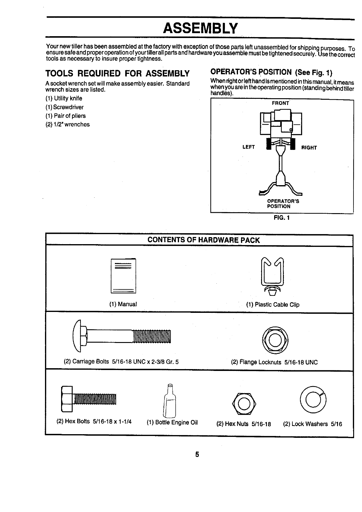
2