SeasonsComfort Anchor Point 158718 User manual

Anchor Point™ Two Handle Bath Kit,
With Quick Install Pop Up, Chrome, 1.2 GPM
Exclusively Distributed By:
Atlanta, GA 30339
To Reorder:
1-800-431-3000
hdsupplysolutions.com
1
Kit Anchor Point™ para baño de doble maneral,
con sistema emergente de instalación rápida, cromo, 1.2 GPM
Part #: 158718
Mfg #: P67223W-8001
USN #: 320280252
HD Supply
© 2022
NSF/ANSI/CAN 61: Q ≤ 1

Preparation / Preparación
Before beginning the assembly of this product, make sure all parts are present. Compare parts with the package contents list. If any part is missing or
damaged, do not attempt to assemble the product. Contact customer service for replacement parts.
Antes de comenzar el ensamblaje del producto, asegúrese de tener todas las piezas. Compare las piezas con la lista del contenido del paquete y el
diagrama. No intente ensamblar el producto si falta alguna pieza o si estas están dañadas.
Tools You Will Need / Herramientas que necesitarás:
Phillips Screwdriver
Destornillador Phillips
Safety Goggles
Gafas de Seguridad
Silicone Sealant
Sellador de Silicona
SILICONE
(2) Supply Lines
2 Líneas de Suministro
13
Adjustable Wrench
Llave Ajustable
Tape Measure
Cinta de Medir
Phillips Screwdriver
Destornillador Phillips
Flathead Screwdriver
Destornillador de
Cabeza Plana
Electric Drill
Taladro Eléctrico
Level
Nivel
Pencil
Lápiz
2

F
Package Contents / Contenido del Paquete
Part
Pieza
Description
Descripción
Quantity
Cantidad
ATowel bar post (left) /
Poste para toallero (izquierdo) 2
B24in Towel bar /
Toallero de 24 plg (60,96 cm) 1
CTowel bar post (right) /
Poste para toallero (derecho) 2
DPaper holder /
Portarrollos de papel higiénico 1
ETowel ring / Aro para toalla 1
FFaucet / Grifo 1
Part
Pieza
Description
Descripción
Quantity
Cantidad
KWasher / Arandela 1
LRubber Washer / Arandela de Goma 1
MMetal Washer / Arandela de Metal 1
NLock Nut / Tuerca de Bloqueo 1
ODrain Body / Cuerpo del Drenaje 1
PJoint / Junta 1
Horizontal Rod / Varilla HorizontalQ 1
NOTE: *Items I - O come pre-assembled.
NOTA: *Los artículos I - O vienen preensamblados.
G
H
T
I*
J*
L*
M*
R
S
N*
O*
Q
K*
GGasket / Junta 1
P
HQuick Install Nut /
Tuerca de Instalación Rápida 2
C
B
A
E
A
D
C
IPop Up Stopper / Tapón Emergente 1
JPop-Up Flange / Brida Emergente 1
RLift Rod Strap /
Correa de la Varilla de Elevación 1
SClip / Sujetador 1
Lift Rod / Varilla de ElevaciónT 1
3

Bath Kit Instructions / Instrucciones del kit para baño
12
2 Installing the mounting brackets
Drill 1/4 in. holes in the previously marked locations.
□
3 Installing the product
Place the post over the mounting bracket (BB) and secure it with the
set screw (DD), as shown.
□
NOTE: The included template (EE) may be used to mark the mounting
locations for the towel bars: A and B for the tissue holder / A and
C for the 24 in. towel bar.
NOTE: When mounting the products to a wood wall, fasten the mounting
brackets (BB) to the wall using the wood screws (AA). There will
be no need for drilling or plastic anchors (CC).
Push the plastic anchors (CC) flush into the dry wall.
□
Fasten the mounting bracket (BB) to the wall with
the wood screws (AA).
□
□Repeat this step as needed for each bath accessory.
□
□
□
□
□Repeat this step for the remaining post.
NOTE: Ensure the towel bar is inserted prior to securing the second post to the
mounting bracket (BB).
BB AA
CC
BB
AA
Cómo marcar el lugar de montaje Cómo instalar los soportes de
montaje
Taladra orificios de 1/4 plg en los lugares marcados
anteriormente.
Cómo instalar el producto
Coloca el poste sobre el soporte de montaje (BB) y asegúralo con
el tornillo de fijación (DD), como se muestra.
NOTA: La plantilla (EE) incluida puede ser usada para marcar los lugares de
montaje para los toalleros: A y B para el Portarrollos de papel higiénico /
A y C para el toallero de 61 cm.
NOTA: Cuando instales los productos en una pared de madera, fija los
soportes de montaje (BB) a la pared usando tornillos para
madera (AA). No habrá necesidad de taladrar o de colocar
anclajes de plástico (CC).
Empuja los anclajes de plástico (CC) hasta insertarlos
a ras en el drywall.
Fija el soporte de montaje (BB) a la pared con los
tornillos para madera (AA).
Repite este paso las veces que sea necesario para
cada accesorio de baño.
Repite este paso para el otro poste.
NOTA: Cerciórate de que el toallero esté insertado antes de asegurar el segundo
poste al soporte de montaje (BB).
BB
DD
DD
BB
15mm
1 Marking the mounting location
Remove the set screw (DD) from the base of the
product post(s).
Place the product in the desired mounting location,
using a level to position it accordingly, and use a pencil
to lightly mark the outline of the post(s).
Center the mounting bracket (BB) within the marked post
location(s), and mark where the screw holes will be drilled.
Repeat this step as needed for each bath accessory.
Quita el tornillo de fijación (DD) de la base del poste
del producto.
Coloca el producto en el lugar de montaje deseado
usando un nivel para colocarlo adecuadamente y usa
un lápiz para marcar ligeramente el contorno en el poste(s).
Centra el soporte de montaje (BB) dentro del lugar(es)
señalado(s) en el poste y marca donde se taladrarán los
orificios de los tornillos.
Repite este paso las veces que sea necesario para cada
accesorio de baño.
3
4

1 2
Assembly Instructions / Instrucciones de Ensamblaje
G
F
HSink
Lavamanos
Sink
Lavamanos
Push
up
Empue
hacia
arriba
Screw/Tornillo
Fig 1
H
F
SILICONE
34
I
J
K
Preparing the pop-up assembly:
Remove the pop-up stopper (I), drain flange (J) and washer (K) from
the drain body (O).
Cómo preparar el ensamblaje emergente:
Retira el tapón emergente (I), la brida del desagüe (J) y la arandela
(K) del cuerpo del desagüe (O).
1
2
N
L
M1
J
K
Shut off water supply at angle stop. Remove old faucet. Clean sink
surface in preparation for new faucet. Ensure the gasket (G) is on the
bottom of the new faucet (F). Place the faucet (F) through the
mounting holes in the sink.
NOTE: Silicone sealant is required under the gasket (G).
Cierra el suministro de agua en la válvula de cierre angular. Retira
la mezcladora existente. Limpia la superficie del fregadero en
preparación para una nueva mezcladora. Asegúrate de que la junta
(G) esté en la parte inferior de la mezcladora nueva (F). Coloca la
mezcladora (F) en los orificios de montaje del lavabo.
NOTA: Se requiere aplicar silicona debajo de la junta (G).
O
Installing the drain body:
Insert the washer (K) into the drain flange (J) and place the drain
flange (J) into the drain hole of the sink. From underneath the sink,
screw the drain body (O) onto the drain flange (J). Ensure that the
opening (1) for the ball rod on the drain body (O) faces towards the
rear of the sink. Tighten the rubber washer (L), metal washer (M)
and lock nut (N) on the drain body (O). Hand-tighten only.
Cómo instalar el cuerpo del drenaje:
Inserta la arandela (K) en la brida del desagüe (J) y coloca la brida
(J)en el orificio de desagüe del lavamanos. Desde la parte inferior
del lavabo, enrosca el cuerpo del drenaje (O) en la brida del drenaje
(J). Asegúrate de que la abertura (1) para la varilla de bola del
cuerpo del drenaje (O) esté frente a la parte posterior del lavabo.
Ajusta la arandela de goma (L), la arandela de metal (M) y la
contratuerca (N) en el cuerpo del desagüe (O). Ajusta sólo con la
mano.
O
From underneath the sink, secure the faucet assembly to the sink
with the quick install nut (H). Push the quick install nut (H) up over the
threads until it stops against the bottom of the sink, then hand turn
(clockwise) to tighten, as shown in the Fig 1.
Desde la parte inferior del lavabo, asegure el ensamble del grifo al
lavabo con la tuerca de instalación rápida (H). Presione la tuerca de
instalación rápida (H) hacia arriba sobre las roscas hasta que se
detenga al alcanzar la parte inferior del lavabo, luego apriete a mano
(en dirección de las manecillas del reloj) para apretarla, como se
muestra en la Fig. 1.
5

5
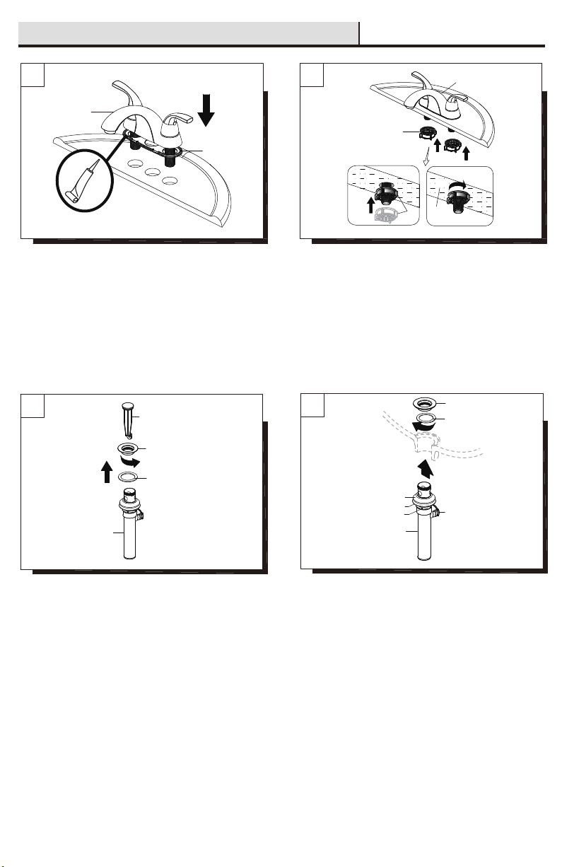
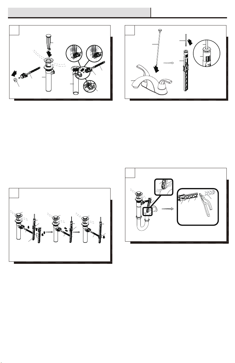
Installing the lift rod:
Slide the lift rod (T) down into the lift rod strap (R) through the faucet
(F) until it clicks into the lift rod strap (R).
6
7
8
Assembly Instructions / Instrucciones De Ensamblaje
Cómo instalar la varilla de elevación:
Desliza la varilla de elevación (T) hacia abajo en la correa de la
varilla (R) y a través del grifo (F) hasta que haga clic dentro de la
correa (R).
2
T
R
T
R
1
T
F
1
Q
2
O
I
3
Insert 3
Folleto 3
Insert 2
Folleto 2
P
Q
O
P
1
I
1
Q
Hole
Orificio
3
3
S
R
2
Q
4
4
I
S
R
5
Q
S
R
I
R
1
2
R
R
S
Fig. 1
Fig. 2
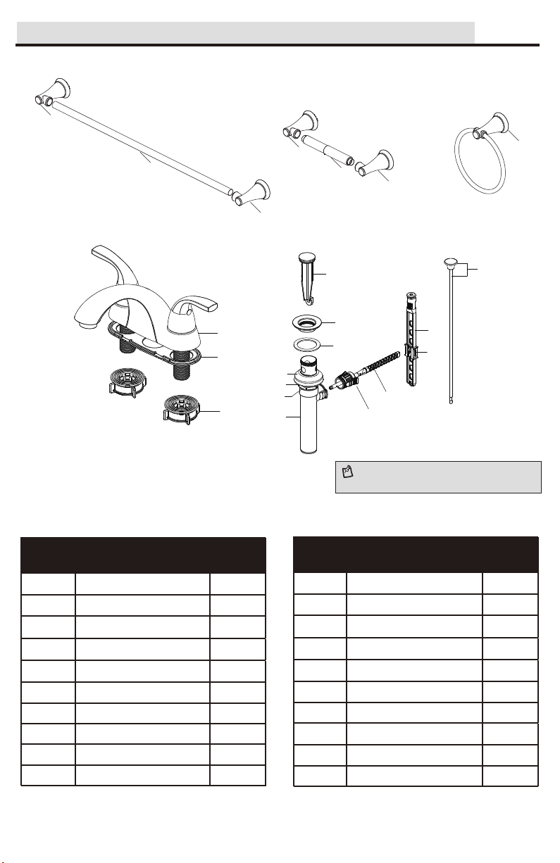
Installing the stopper and horizontal rod:
Before installation, unscrew the protective cap (1) from the horizontal
rod (Q). Insert the stopper (I) into the drain hole in the sink. Insert the
horizontal rod (Q) into the drain body (O) and through the hole of the
stopper (I) until you hear a click. See insert 2. You can press the two
sides of the joint (P) to remove the horizontal rod (Q).
Note: For easier removal and cleaning, rotate the stopper (I) 90
degrees so that the horizontal rod (Q) does not go through the hole in
the stopper (I). See insert 3.
Cómo instalar el tapón y la varilla horizontal:
Antes de la instalación, desenrosca la tapa protectora (1) de la
varilla horizontal (Q). Inserta el tapón (I) en el orificio del drenaje del
lavabo. Inserta la varilla horizontal (Q) en el cuerpo del desagüe (O)
y a través del orificio del tapón (I) hasta que escuches un clic.
Consulta el folleto 2. Puedes presionar ambos lados de la junta (P)
para retirar la varilla horizontal (Q).
Nota: Para retirar y limpiar más fácilmente, gira el tapón (I) a 90º de
manera que la varilla horizontal (Q) no atraviese el orificio del tapón
(I). Consulta el folleto 3.
Attaching the horizontal rod and strap:
Press the horizontal rod (Q) down to ensure the stopper (I) is in the
maximum open position. Slide the clip (S) upward, adjust the location
of the lift rod strap (R) to the appropriate height and insert the
horizontal rod (Q) with the correct hole of the lift rod strap (R). Move
the lift rod strap (R) in or out to choose an appropriate location. Slide
the clip (S) downward until it secures with the horizontal rod (Q).
Cómo instalar la varilla horizontal y la correa:
Presiona hacia abajo la varilla horizontal (Q) para garantizar que el
tapón (I) esté abierto completamente. Desliza la presilla (S) hacia
arriba, ajusta la ubicación de la correa de la varilla de elevación (R) a
la altura adecuada e inserta la varilla horizontal (Q) con el orificio
correcto de la varilla de elevación (R). Mueve la correa de la varilla
de elevación (R) hacia adentro o hacia afuera para seleccionar la
ubicación adecuada. Desliza la presilla (S) hacia abajo hasta que la
varilla horizontal (Q) esté asegurada.
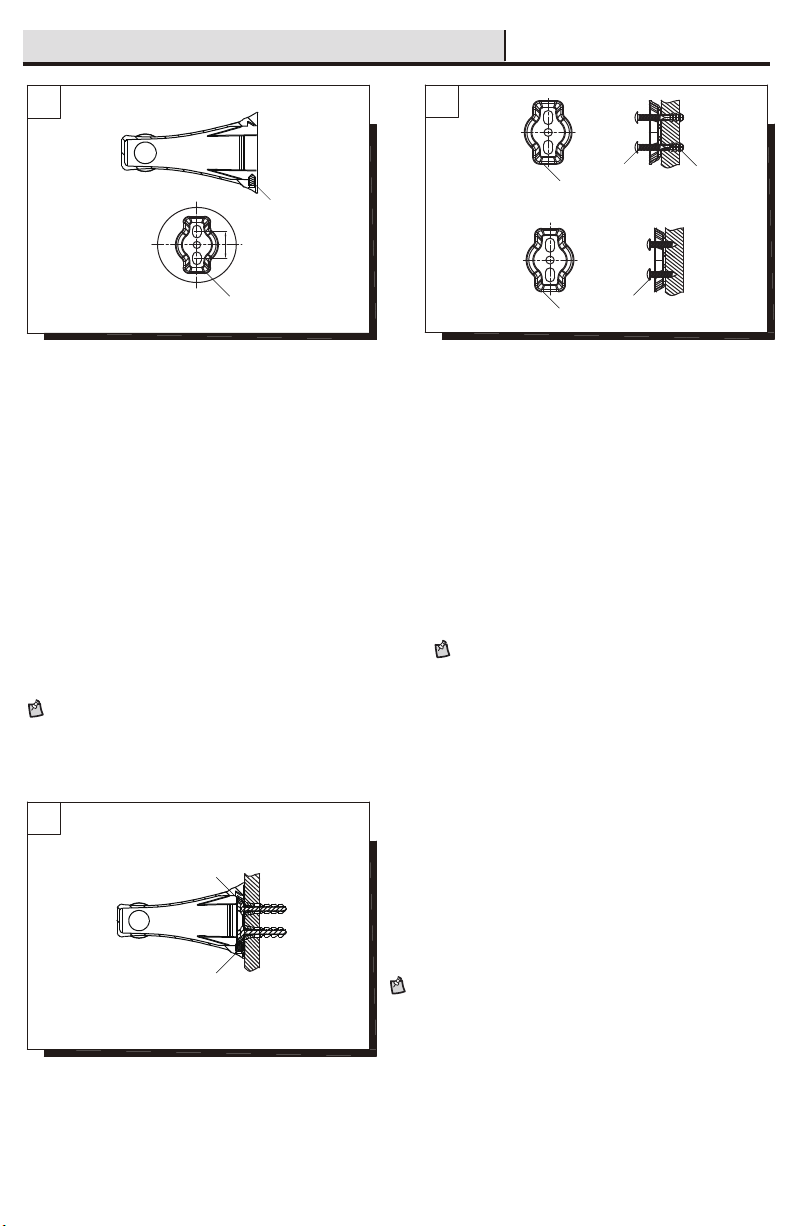
Adjusting the length of lift rod strap (optional):
If the pop up lift rod strap (R) is interfering with your installation, as
shown in Fig. 1, the lift rod strap (R) can be cut shorter. Once you
have identified the proper hole in the lift rod strap (R) that is
necessary for your installation, you may cut off the bottom portion (1)
of the lift rod strap (R) by snapping it off with pliers or cutting it off
with a saw at the cutting point (2), as shown in Fig. 2. Ensure the clip
(S) does not slide off the lift rod strap (R).
Cómo ajustar el largo de la correa de la varilla de elevación
(opcional):
Si la presilla de la varilla de elevación (R) interfiere con tu
instalación, como se muestra en la Fig. 1, la presilla de la varilla de
elevación (R) puede recortarse. Una vez que hayas identificado el
orificio adecuado en la presilla de la varilla de elevación (R) que es
necesario para tu instalación, puedes recortar la porción inferior (1)
de la presilla de la varilla de elevación (R) partiendo con alicates o
cortando con una sierra en el punto de corte (2), como se muestra
en la Fig. 2. Asegúrate de que la presilla (S) no se salga de la
correa de la varilla de elevación (R).
6

Make connections to water lines. Use 1/2" I.P.S. faucet connections
(2) or use supply line coupling nuts (3)(not included) with 3/8"
O.D.ball-nose riser (1). Use wrenches to tighten connections. Do not
overtighten.
Conecte a las líneas de suministro. Use conexiones de grifos de
1/2" IPS (2) o tuercas de acoplamiento de líneas de suministro (3)
(no incluidas) con un tubo montante de bola de diámetro exterior
de 3/8" (1). Use llaves para apretar las conexiones. No apriete
demasiado.
2
3
1
910
Assembly Instructions / Instrucciones De Ensamblaje
Flushing and checking for leaks:
Important: After installation is completed, remove aerator. Turn on
water supply and allow both hot and cold water to run for at least one
minute each. While water is running, check for leaks. Replace
aerator. This flushes away any debris that could cause damage to
internal parts. Do not lose the gasket (1) in the aerator.
Cómo purgar las tuberías y comprobar que no haya fugas:
Importante: Una vez que termine la instalación, quite el aireador.
Abra el suministro de agua y deje correr agua fría y caliente durante
al menos un minuto cada una. Mientras el agua corre, controle que
no haya pérdidas. Reemplace el aireador. Esto limpia cualquier
residuo que pueda causar daño a las partes internas. No a ojes la
junta (1) en el aireador.
1
□To clean, wipe down with a damp cloth and dry with a towel.
□Do not use abrasive cleaners, steel wool, or harsh chemicals when cleaning this faucet, or the warranty will be voided.
Care and Cleaning / Cuidado y Limpieza
Para limpiar, usa un paño húmedo y seca con una toalla.
No uses limpiadores abrasivos, esponjas de alambre o productos químicos fuertes para limpiar esta mezcladora, pues ello anulará la garantía.
□
□
□
Preserve the finish of the bath accessory using a non-abrasive wax.
When using non-abrasive cleaners, rinse off immediately when finished cleaning the bath accessory.
Do not use abrasive cleaners when cleaning this bath accessory.
Para preservar el acabado del accesorio de baño, usa cera no abrasiva.
Al usar limpiadores no abrasivos, enjuaga de inmediato tras concluir la limpieza del accesorio de baño.
No uses limpiadores abrasivos al limpiar este accesorio de baño.
7

If you've followed the instructions carefully and your faucet still does not work properly, take these corrective steps.
There are leaks from the handle.
The aerator has an irregular or
reduced water flow.
The aerator is dirty or not properly
installed.
Tighten the bonnet nut. Clean or replace
the o-ring.
Remove the aerator and check for
debris. Ensure that the rubber washer is
properly installed.
Remove the handle to check the
cartridge. Clean or replace.
The water will not shut off completely. The cartridge is dirty or broken.
Problem
Problema
Cause
Causa
Action
AcciIón
10 Cartridge C / Cartucho C
11 Gasket / Junta
9 Cartridge H / Cartucho H
186871
186926
186842
186936
7 Inverter / Inversor 186855
8 Washer / Arandela 186810
4 Handle C / Llave C
186881
3 Handle H / Llave H
186858
6 Screw / Tornillo
158765
5 Bonnet Nut / Tuerca del Bonete
Troubleshooting / Solución de Problemas
Hay filtración por el maneral. Aprieta la tuerca del bonete. Limpia o
reemplaza el aro tórico.
El aireador tiene un fiujo de agua
irregular o reducido.
El aireador está sucio o mal instalado. Retira el aireador y verifica si hay
suciedades. Asegúrate de que la
arandela de goma esté bien instalada.
Retira la llave para revisar el cartucho.
Limpia o reemplaza.
El suministro de agua no se corta
completamente.
El cartucho está sucio o dañado.
Replacement Parts / Repuestos
Si usted ha seguido las instrucciones cuidadosamente y su grifo todavía no funciona correctamente, sigue estos pasos correctivos.
Part
Pieza
Description
Descripción
12 Aerator / Aireador 158766
Apply additional silicone sealant to the beveled
side of the drain flange. Retighten and test for
leaks.
There is leaking from the sink drain at the
base of the sink.
The sink has a rough or irregular surface.
Aplica más sellador de silicona al lado biselado
de la brida del drenaje. Aprieta nuevamente y
verifica que no haya filtraciones.
Hay una filtración proveniente del desagüe
del lavamanos en su base.
El lavamanos tiene una superficie rugosa
o irregular.
4
5
6
7
8
9
10
11
12
13
Faucet ID tags
can be found by
removing the hot
water handle
Las etiquetas de
identificación de
la mezcladora
pueden verse al
quitar el maneral
del agua caliente
3
13 Quick Install Nut / Tuerca de Instalación Rápida 186846
14
14 Lift Rod / Varilla de Elevación 186889
15 Pop-Up Assembly / Ensamblaje de Sistema
Emergente
183940
15
La tuerca ciega se aflojó y el aro tórico del
cartucho está sucio o dañado.
The bonnet nut has come loose or the
o-ring on the cartridge is dirty or damaged.
2
1
2
1
2
1
186849
2 Set Screw / Tornillo de fijación
186863
1 Mounting Hardware (screw, bracket, and
plastic anchor) / Herrajes de montaje
(tornillo, soporte, y anclaje de plástico)
8
Part #
Pieza #
USN #
USN #
322096815
322096440
322096660
322096434
322096811
Table of contents
Other SeasonsComfort Plumbing Product manuals
Popular Plumbing Product manuals by other brands

Kohler
Kohler COMPONENTS K-EX27462T-NW-CP installation instructions

Hans Grohe
Hans Grohe PuraVida Assembly instructions

Hewi
Hewi 950 Installation and operating instructions

Kallista
Kallista Quincy P23075 installation instructions

Franke
Franke AQUA201 Installation and operating instructions

Franke
Franke 2000108750 Installation and operating instructions