SeasonsComfort Anchor Point 67223W-8004 User manual
Anchor Point™ Two Handle Bath Faucet,
With Quick Install Pop Up, Brushed Nickel, 1.2 GPM
Exclusively Distributed By:
Atlanta, GA 30339
To Reorder:
1-800-431-3000
hdsupplysolutions.com
1
Mezcladora Anchor Point™ para baño de doble maneral,
con sistema emergente de instalación rápida, níquel cepillado, 1.2 GPM
Part #: 158717
Mfg #: 67223W-8004
USN #: 320280253
HD Supply
© 2022
NSF/ANSI/CAN 61: Q ≤ 1

Preparation / Preparación
Before beginning the assembly of this product, make sure all parts are present. Compare parts with the package contents list. If any part is missing or
damaged, do not attempt to assemble the product. Contact customer service for replacement parts.
A
Package Contents / Contenido del Paquete
Antes de comenzar el ensamblaje del producto, asegúrese de tener todas las piezas. Compare las piezas con la lista del contenido del paquete y el
diagrama. No intente ensamblar el producto si falta alguna pieza o si estas están dañadas.
Tools You Will Need / Herramientas que necesitarás:
Phillips Screwdriver
Destornillador Phillips
Safety Goggles
Gafas de Seguridad
Silicone Sealant
Sellador de Silicona
SILICONE
(2) Supply Lines
2 Líneas de Suministro
13
Adjustable Wrench
Llave Ajustable
Part
Pieza
Description
Descripción
Quantity
Cantidad
AFaucet / Grifo 1
BGasket / Junta 1
CQuick Install Nut / Tuerca de
Instalación Rápida 2
DPop Up Stopper / Tapón Emergente 1
EPop-Up Flange / Brida Emergente 1
FWasher / Arandela 1
Part
Pieza
Description
Descripción
Quantity
Cantidad
ILock Nut / Tuerca de Bloqueo 1
JDrain Body / Cuerpo del Drenaje 1
KJoint / Junta 1
LHorizontal Rod / Varilla Horizontal 1
MLift Rod Strap / Correa de la Varilla
de Elevación 1
NClip / Sujetador 1
Lift Rod / Varilla de ElevaciónO 1
NOTE: *Items D - J come pre-assembled.
NOTA: *Los artículos D - J vienen preensamblados.
B
C
O
D*
E*
G*
H*
M
N
I*
J*
L
F*
GRubber Washer / Arandela de Goma 1
K
HMetal Washer / Arandela de Metal 1
2
1 2
Assembly Instructions / Instrucciones de Ensamblaje
B
A
CSink
Lavamanos
Sink
Lavamanos
Push
up
Empue
hacia
arriba
Screw/Tornillo
Fig 1
C
A
SILICONE
34
D
E
F
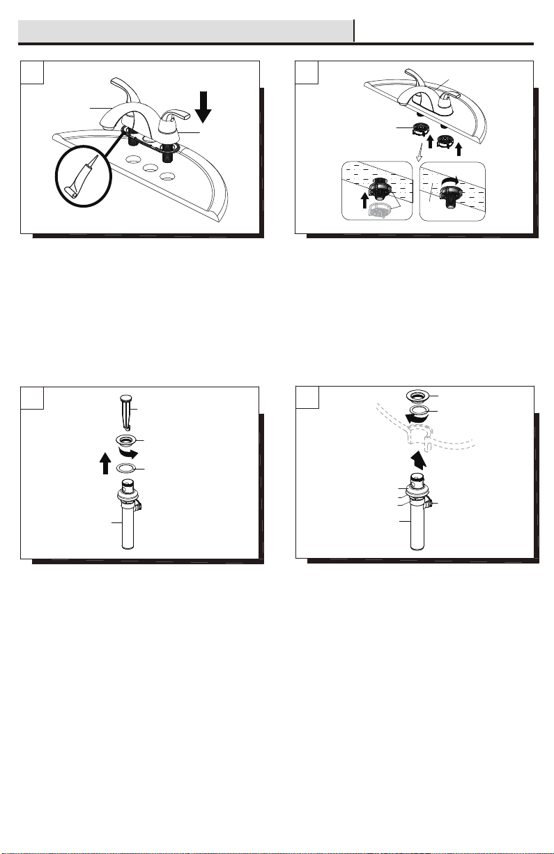
Preparing the pop-up assembly:
Remove the pop-up stopper (D), drain flange (E) and washer (F) from
the drain body (J).
Cómo preparar el ensamblaje emergente:
Retira el tapón emergente (D), la brida del desagüe (E) y la arandela
(F) del cuerpo del desagüe (J).
1
2
I
G
H1
E
F
Shut off water supply at angle stop. Remove old faucet. Clean sink
surface in preparation for new faucet. Ensure the gasket (B) is on the
bottom of the new faucet (A). Place the faucet (A) through the
mounting holes in the sink.
NOTE: Silicone sealant is required under the gasket (B).
Cierra el suministro de agua en la válvula de cierre angular. Retira
la mezcladora existente. Limpia la superficie del fregadero en
preparación para una nueva mezcladora. Asegúrate de que la junta
(B) esté en la parte inferior de la mezcladora nueva (A). Coloca la
mezcladora (A) en los orificios de montaje del lavabo.
NOTA: Se requiere aplicar silicona debajo de la junta (B).
J
Installing the drain body:
Insert the washer (F) into the drain flange (E) and place the drain
flange (E) into the drain hole of the sink. From underneath the sink,
screw the drain body (J) onto the drain flange (E). Ensure that the
opening (1) for the ball rod on the drain body (J) faces towards the
rear of the sink. Tighten the rubber washer (G), metal washer (H)
and lock nut (I) on the drain body (J). Hand-tighten only.
Cómo instalar el cuerpo del drenaje:
Inserta la arandela (F) en la brida del desagüe (E) y coloca la brida
(E)en el orificio de desagüe del lavamanos. Desde la parte inferior
del lavabo, enrosca el cuerpo del drenaje (J) en la brida del drenaje
(E). Asegúrate de que la abertura (1) para la varilla de bola del
cuerpo del drenaje (I) esté frente a la parte posterior del lavabo.
Ajusta la arandela de goma (G), la arandela de metal (H) y la
contratuerca (I) en el cuerpo del desagüe (J). Ajusta sólo con la
mano.
J
From underneath the sink, secure the faucet assembly to the sink
with the quick install nut (C). Push the quick install nut (C) up over the
threads until it stops against the bottom of the sink, then hand turn
(clockwise) to tighten, as shown in the Fig 1.
Desde la parte inferior del lavabo, asegure el ensamble del grifo al
lavabo con la tuerca de instalación rápida (C). Presione la tuerca de
instalación rápida (C) hacia arriba sobre las roscas hasta que se
detenga al alcanzar la parte inferior del lavabo, luego apriete a mano
(en dirección de las manecillas del reloj) para apretarla, como se
muestra en la Fig. 1.
3
5
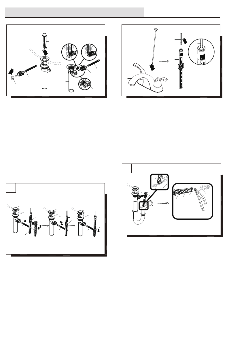
Installing the lift rod:
Slide the lift rod (O) down into the lift rod strap (M) through the faucet
(A) until it clicks into the lift rod strap (M).
6
7
8
Assembly Instructions / Instrucciones De Ensamblaje
Cómo instalar la varilla de elevación:
Desliza la varilla de elevación (O) hacia abajo en la correa de la
varilla (M) y a través del grifo (A) hasta que haga clic dentro de la
correa (M).
2
O
M
O
M
1
O
A
1
L
2
J
D
3
Insert 3
Folleto 3
Insert 2
Folleto 2
K
L
J
K
1
D
1
L
Hole
Orificio
3
3
N
M
2
L
4
4
D
N
M
5
L
N
M
D
M
1
2
M
M
N
Fig. 1
Fig. 2
Installing the stopper and horizontal rod:
Before installation, unscrew the protective cap (1) from the horizontal
rod (L). Insert the stopper (D) into the drain hole in the sink. Insert the
horizontal rod (L) into the drain body (J) and through the hole of the
stopper (D) until you hear a click. See insert 2. You can press the two
sides of the joint (K) to remove the horizontal rod (L).
Note: For easier removal and cleaning, rotate the stopper (D) 90
degrees so that the horizontal rod (L) does not go through the hole in
the stopper (D). See insert 3.
Cómo instalar el tapón y la varilla horizontal:
Antes de la instalación, desenrosca la tapa protectora (1) de la
varilla horizontal (L). Inserta el tapón (D) en el orificio del drenaje del
lavabo. Inserta la varilla horizontal (L) en el cuerpo del desagüe (J)
y a través del orificio del tapón (D) hasta que escuches un clic.
Consulta el folleto 2. Puedes presionar ambos lados de la junta (K)
para retirar la varilla horizontal (L).
Nota: Para retirar y limpiar más fácilmente, gira el tapón (D) a 90º
de manera que la varilla horizontal (L) no atraviese el orificio del
tapón (D). Consulta el folleto 3.
Attaching the horizontal rod and strap:
Press the horizontal rod (L) down to ensure the stopper (D) is in the
maximum open position. Slide the clip (N) upward, adjust the location
of the lift rod strap (M) to the appropriate height and insert the
horizontal rod (L) with the correct hole of the lift rod strap (M). Move
the lift rod strap (M) in or out to choose an appropriate location. Slide
the clip (N) downward until it secures with the horizontal rod (L).
Cómo instalar la varilla horizontal y la correa:
Presiona hacia abajo la varilla horizontal (L) para garantizar que el
tapón (D) esté abierto completamente. Desliza la presilla (N) hacia
arriba, ajusta la ubicación de la correa de la varilla de elevación (M) a
la altura adecuada e inserta la varilla horizontal (L) con el orificio
correcto de la varilla de elevación (M). Mueve la correa de la varilla
de elevación (M) hacia adentro o hacia afuera para seleccionar la
ubicación adecuada. Desliza la presilla (N) hacia abajo hasta que la
varilla horizontal (L) esté asegurada.
Adjusting the length of lift rod strap (optional):
If the pop up lift rod strap (M) is interfering with your installation, as
shown in Fig. 1, the lift rod strap (M) can be cut shorter. Once you
have identified the proper hole in the lift rod strap (M) that is
necessary for your installation, you may cut off the bottom portion (1)
of the lift rod strap (M) by snapping it off with pliers or cutting it off
with a saw at the cutting point (2), as shown in Fig. 2. Ensure the clip
(N) does not slide off the lift rod strap (M).
Cómo ajustar el largo de la correa de la varilla de elevación
(opcional):
Si la presilla de la varilla de elevación (M) interfiere con tu
instalación, como se muestra en la Fig. 1, la presilla de la varilla de
elevación (M) puede recortarse. Una vez que hayas identificado el
orificio adecuado en la presilla de la varilla de elevación (M) que es
necesario para tu instalación, puedes recortar la porción inferior (1)
de la presilla de la varilla de elevación (M) partiendo con alicates o
cortando con una sierra en el punto de corte (2), como se muestra
en la Fig. 2. Asegúrate de que la presilla (N) no se salga de la
correa de la varilla de elevación (M).
4

Make connections to water lines. Use 1/2" I.P.S. faucet connections
(2) or use supply line coupling nuts (3)(not included) with 3/8"
O.D.ball-nose riser (1). Use wrenches to tighten connections. Do not
overtighten.
Conecte a las líneas de suministro. Use conexiones de grifos de
1/2" IPS (2) o tuercas de acoplamiento de líneas de suministro (3)
(no incluidas) con un tubo montante de bola de diámetro exterior
de 3/8" (1). Use llaves para apretar las conexiones. No apriete
demasiado.
2
3
1
910
Assembly Instructions / Instrucciones De Ensamblaje
Flushing and checking for leaks:
Important: After installation is completed, remove aerator. Turn on
water supply and allow both hot and cold water to run for at least one
minute each. While water is running, check for leaks. Replace
aerator. This flushes away any debris that could cause damage to
internal parts. Do not lose the gasket (1) in the aerator.
Cómo purgar las tuberías y comprobar que no haya fugas:
Importante: Una vez que termine la instalación, quite el aireador.
Abra el suministro de agua y deje correr agua fría y caliente durante
al menos un minuto cada una. Mientras el agua corre, controle que
no haya pérdidas. Reemplace el aireador. Esto limpia cualquier
residuo que pueda causar daño a las partes internas. No a ojes la
junta (1) en el aireador.
1
5
□To clean, wipe down with a damp cloth and dry with a towel.
□Do not use abrasive cleaners, steel wool, or harsh chemicals when cleaning this faucet, or the warranty will be voided.
If you've followed the instructions carefully and your faucet still does not work properly, take these corrective steps.
There are leaks from the handle.
The aerator has an irregular or
reduced water flow.
The aerator is dirty or not properly
installed.
Tighten the bonnet nut. Clean or replace
the o-ring.
Remove the aerator and check for
debris. Ensure that the rubber washer is
properly installed.
Remove the handle to check the
cartridge. Clean or replace.
The water will not shut off completely. The cartridge is dirty or broken.
Problem
Problema
Cause
Causa
Action
AcciIón
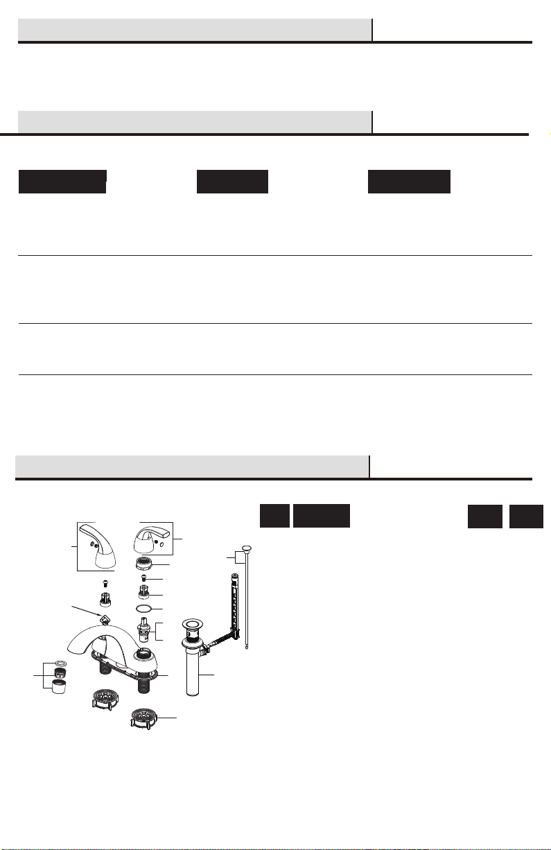
8 Cartridge C / Cartucho C
9 Gasket / Junta
7 Cartridge H / Cartucho H
186887
186926
186842
186936
5 Inverter / Inversor 186855
6 Washer / Arandela 186810
2 Handle C / Llave C
186905
1 Handle H / Llave H
186858
4 Screw / Tornillo
158765
3 Bonnet Nut / Tuerca del Bonete
Care and Cleaning / Cuidado y Limpieza
Troubleshooting / Solución de Problemas
Hay filtración por el maneral. Aprieta la tuerca del bonete. Limpia o
reemplaza el aro tórico.
El aireador tiene un fiujo de agua
irregular o reducido.
El aireador está sucio o mal instalado. Retira el aireador y verifica si hay
suciedades. Asegúrate de que la
arandela de goma esté bien instalada.
Retira la llave para revisar el cartucho.
Limpia o reemplaza.
El suministro de agua no se corta
completamente.
El cartucho está sucio o dañado.
Replacement Parts / Repuestos
Si usted ha seguido las instrucciones cuidadosamente y su grifo todavía no funciona correctamente, sigue estos pasos correctivos.
□Para limpiar, usa un paño húmedo y seca con una toalla.
□No uses limpiadores abrasivos, esponjas de alambre o productos químicos fuertes para limpiar esta mezcladora, pues ello anulará la garantía.
Part
Pieza
Description
Descripción
10 Aerator / Aireador 186891
Apply additional silicone sealant to the beveled
side of the drain flange. Retighten and test for
leaks.
There is leaking from the sink drain at the
base of the sink.
The sink has a rough or irregular surface.
Aplica más sellador de silicona al lado biselado
de la brida del drenaje. Aprieta nuevamente y
verifica que no haya filtraciones.
Hay una filtración proveniente del desagüe
del lavamanos en su base.
El lavamanos tiene una superficie rugosa
o irregular.
2
3
4
5
6
7
8
9
10
11
Faucet ID tags
can be found by
removing the hot
water handle
Las etiquetas de
identificación de
la mezcladora
pueden verse al
quitar el maneral
del agua caliente
1
11 Quick Install Nut / Tuerca de Instalación Rápida 186846
12
12 Lift Rod / Varilla de Elevación 186868
13 Pop-Up Assembly / Ensamblaje de Sistema
Emergente
13
La tuerca ciega se aflojó y el aro tórico del
cartucho está sucio o dañado.
The bonnet nut has come loose or the
o-ring on the cartridge is dirty or damaged.
6
Part #
Pieza #
USN #
USN #
322096815
322096440
322096456
322096434
183926 322096642
Table of contents
Other SeasonsComfort Plumbing Product manuals


Popular Plumbing Product manuals by other brands

American Standard
American Standard Madera FloWise 15" Height 1.28 GPF Flushometer Toilet... Specification sheet

Hans Grohe
Hans Grohe ShowerSelect 15763 1 Series Installation/User Instructions/Warranty

Gessi
Gessi VIA MANZONI 38731 manual

Hans Grohe
Hans Grohe Talis Elegance 33014000 Assembly and operating guide

Hans Grohe
Hans Grohe Novus 71062000 Instructions for use/assembly instructions

Kinedo
Kinedo Smart Express P without threshold PA2901BTNE installation instructions


