SeaSTAR PA1200-2 Quick start guide

Hydraulic Power Assist for SeaStar
Steering Systems
Including:
Before you do it your way,
please try it our way
17
.2
INSTALLATION INSTRUCTIONS
AND OWNER'S MANUAL
www.maritimusboote.de
SEVENTEEN
POINT TWO
ISO 9001

Po er Assist for SeaStar Systems i
Throughout this publi ation, Warnings and Cautions (a ompanied by the
International Hazard Symbol ) are used to alert the manufa turer or
installer to spe ial instru tions on erning a parti ular servi e or
operation that may be hazardous if performed in orre tly or arelessly.
Observe Them Carefully!
These safety alerts alone, annot eliminate the hazards that they
signal. Stri t omplian e to these spe ial instru tions when performing
the installation and maintenan e plus ommon sense operation are major
a ident prevention measures.
Notice to Boat Manu acturer
or Installer
Hazards or unsafe
practices which
COULD result in
minor injury or
product or property
damage.
CAUTION
Hazards or unsafe
practices which
COULD result in
severe personal
injury or death.
WARNING
Immediate hazards
which WILL result in
severe personal
injury or death.
DANGER
Information which is
important to proper
installation or
maintenance, but is
not hazard-related.
NOTICE
Cleaning fluids containing ammonia, acids or any other corrosive
ingredients MUST NOT be used for cleaning any part of this
Hydraulic Steering System. Failure to comply will cause serious
damage to the steering system, resulting in possible loss of
steering, causing property damage, personal injury and/or death.
WARNING
Help protect your boating environment by ensuring that all used oil
is disposed of properly.
NOTICE
NOTICE
Do 't compromise performa ce... use ge ui e
SeaStar parts o ly!
• SeaStar Helms • SeaStar Cylinders
• SeaStar Hoses • SeaStar Oil
Substituting non SeaStar parts in any part of the SeaStar hydrauli
steering system, may seriously ompromise system performan e.
Please e sure this ma ual is left o board the
boat for future refere ce.
Marine Canada Acquisition Inc. DBA SeaStar Solutions is referred to
as SeaStar Solutions throughout this publication.

ii SEASTAR Hydraulics ii
INTRODUCTION
Index
Before Operating Your Boat ........................................................ 1
Compatibility/Tools/Spe ifi ations.............................................. 2
How The System Works ............................................................. 3
Things You Need to Know .......................................................... 4
Before Starting ......................................................................... 4
System Installation Overview...................................................... 5
Specific Installation
Outboard Front Mount & HC5332............................................... 6
Side Mount & Splashwell Mount Cylinders .................................. 9
Inboard & Sterndrive ............................................................... 10
Autopilot Conne tion................................................................ 11
Ele tri al Installation ............................................................... 12
Power Purge Filling and Purging................................................ 14
Manual Filling and Purging ....................................................... 15
Troubleshooting....................................................................... 21
A essories ............................................................................ 23
Mounting Templates ................................................................ 25
Warranty ................................................................................. 29
Before proceeding with the installation, read these instructions
thoroughly. SeaStar Solutions cannot accept responsibility for
installations where instructions have not been followed, where
substitute parts have been used, or modifications have been
made to our products. Warranty may be void if products other
than SeaStar Solutions products are used with this system.
Due to a small amount of internal hydraulic slip, a "master spoke:
or "centered" steering wheel cannot be maintained with a Hydraulic
Steering System. For best results, use an equal distance spoke
steering wheel.
DO NOT use a wire coil type trim switch with a hydraulic steering
system. Wire coil can wind up tight around the steering wheel
shaft and prevent further steering!
PRO Trim offers fingertip trim or ja kplate ontrol with a olumn-
mounted swit h, enabling you to keep both hands on the steering
wheel and on entrate on your driving. PRO Trim PT1000 ontrols
trim or ja kplate only. PRO Trim Dual PT2000 ontrols both fun tions.
NOTICE
WARNING
This installation manual covers
the entire, SeaStar and SeaStar
PRO PA Series. Notes are made,
when required, to cover any
differences between the part
numbers.
NOTICE
SeaStar PRO Power Assist units are to be used with SeaStar PRO
Helms ONLY!
WARNING
The following Power Assist Units are overed in this installation
manual. PA1200-2, PA1225-2 and PA1315-2.

Po er Assist for SeaStar Systems 1
Ensure that the following he k list is arried out
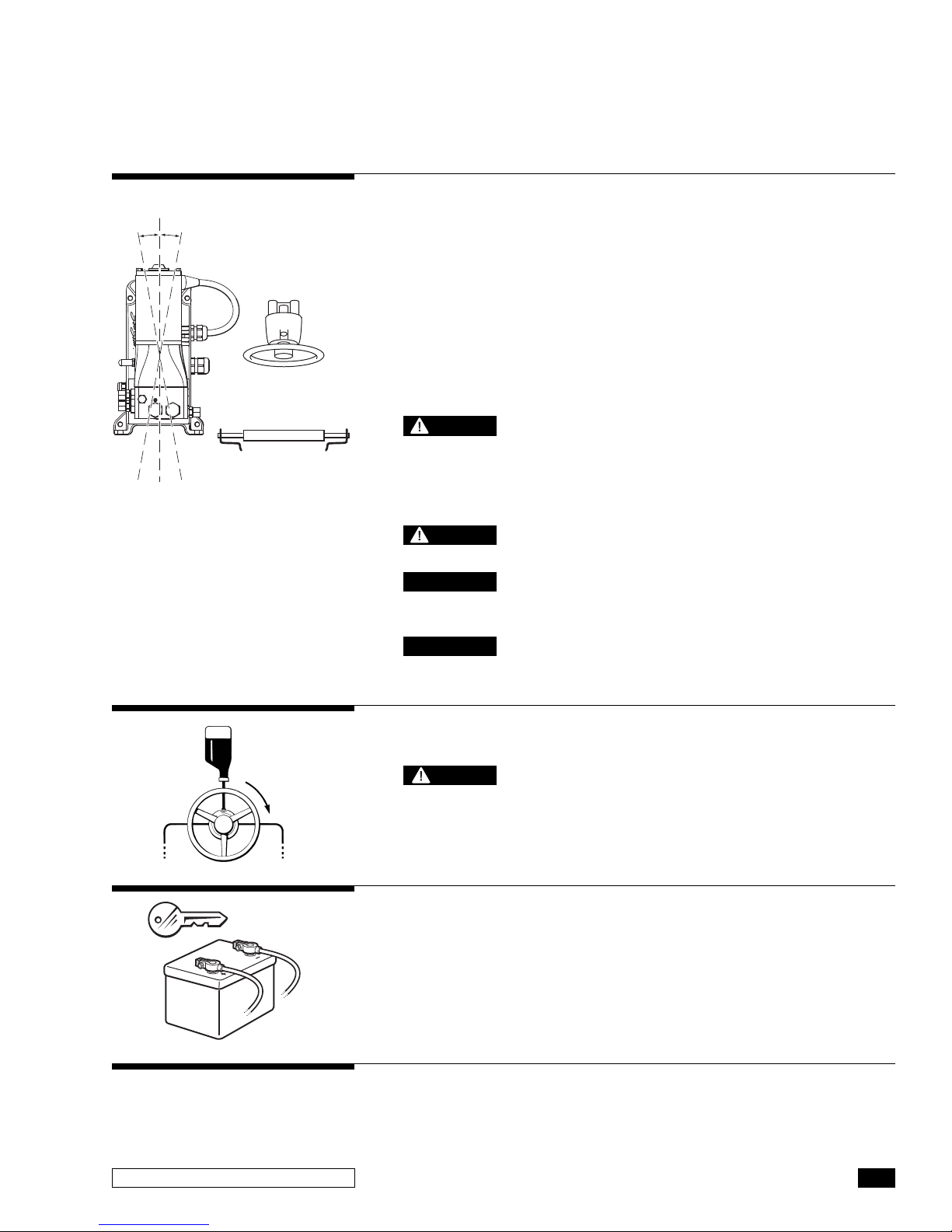
1With the P/A unit "OFF" (ignition off) perform a system pressure
test by turning the helm all the way to hard over and then for ing
the helm another one quarter to one half turn past the stop point.
Inspe t the following areas for leaks.
- Inspe t helm fittings
- Inspe t P/A fittings
- Inspe t ylinder fittings
Look for eviden e of a leak. This test is to be done in BOTH
dire tions. Any leak that is noti ed will need to be repaired
before operating the boat.
2Confirm that extruded nylon tubing has NOT been
substituted for SeaStar/SeaStar PRO Hydraulic Steering hose.
3Confirm that there is no interferen e between the steering
ylinder and the transom, splashwell or ja kplate or any
ombination of these parts by performing these simple steps:
• If installed on an outboard engine, with the engine fully titled,
turn steering from hard over to hard over and onfirm that NO
interferen e o urs. If you are using a hydrauli ja k plate this
also must be performed at the top and bottom position of the
ja k plate. (If interference is present, it MUST be eliminated
with trim limiting switches and/or jack plate restrictors. Contact
Jack plate manufacturer for advice if required.)
• Confirm that the steering ylinder an be stroked fully in both
dire tions as well as full tilt and trim without stret hing and/or
kinking the hydrauli hoses.
• Confirm that the hydrauli hose/tube are not subje ted to hafing,
rubbing or stret hing. Stret hed, kinked or hafed hose/tube will
fail over a period of time leading to loss of steering ontrol.
BEFORE OPERATING
YOUR BOAT
Failure to comply with the above may result in loss of steering
control, leading to collision with obstacle(s), ejection from vessel
resulting in property damage and/or personal injury or death.
WARNING
The SeaStar P/A unit has been
designed and tested for use with
Marine Hydraulic Steering ONLY.
It is not recommended for any
other use. Not complying with
this warning may result in
property damage and/or
personal injury or death.
WARNING
Stretched, kinked or chafed hose will fail over a period of time.
WARNING
When working in an area where fumes from fuel are present, allow
the fumes to disperse completely BEFORE doing any electrical
connection to the battery. Failure to do so may result in an
explosion and or fire.
WARNING
If power to the unit is lost, the SeaStar Power Assist and SeaStar
Power Assist PRO will revert to manual steering, requiring substan-
tially more effort to turn the wheel.
CAUTION

SEASTAR POWER ASSIST 12/24V (PA1200-2 AND PA1225-2)
• 12/24 Volts (automati ally re ognizes)
• 1000psi MAX system peak pressure (500psi working loads)
• Relief pressure 2000psi
• MAX Current Draw = 50 amps
• Typi al urrent draw = ~ 3 amps
• Purple ignition wire MAX urrent draw = 1 amp
SEASTAR PRO POWER ASSIST, 12/24V (PA1315-2)
• 12/24 Volts (automati ally re ognizes)
• 1500psi MAX system peak pressure (500psi working loads)
• Relief pressure 2000psi
• MAX Current Draw = 50 amps
• Typi al urrent draw = ~ 3 amps
• Purple ignition wire MAX urrent draw = 1 amp
2SEASTAR Hydraulics
HYDRAULIC POWER ASSIST
SEASTAR
You will need the following tools to omplete your installation.
• 1/2", 5/8", and 3/4" open end wren h.
• Ele tri al ut and rimp pliers.
• All other tools noted with your Helm Pump and Steering Cylinder
Installation Instru tions.
SeaStar P/A Compatibility Chart
Tools
The P/A and P/A PRO are designed for use in re reational marine
appli ations in onjun tion with SeaStar and SeaStar PRO steering
systems. Optimal performan e will be obtained when used with
SeaStar, or SeaStar PRO 1.4, 1.7 and 2.0 Helm pumps
.
Specifications
3-3/4"
5"
8-3/16"
5/8"
SeaStar nylon tube may ONLY be
used for the compensating line.
DO NOT use SeaStar Nylon tube
to plumb any other portion of the
steering system.
SeaStar P/A PRO is NOT to be used with SeaStar Hydraulic Steering,
performance will be compromised. ONLY use P/A PRO with a SeaStar
PRO Hydraulic steering system and ensure that SeaStar PRO (1500
psi) hose is used to plumb the entire system. (Nylon tubing may be
used for the compensating/return line ONLY.
Use ONLY SeaStar products with
the P/A unit as with ALL SeaStar
systems. Failure to do so may
void your warranty.
The SeaStar Power Assist will automatically recognize the voltage
level once it is connected to an on board power source (refer to
page 12 for electrical connections).
NOTICE
NOTICE
ONLY use SeaStar PRO Power
Assist with a SeaStar PRO helm.
DO NOT
exceed peak operating pressure. 1000psi Standard, 1500psi Pro.
WARNING
Part No.
Harness Length Voltage (auto recognized)
PA1200-2 15' 12/2 Volt
PA1225-2 25' 12/2 Volt
PA1315-2 15' 12/2 Volt
CAUTION
Figure 1.

Po er Assist for SeaStar Systems 3
HOW THE SYSTEM WORKS
SeaStar P/A (Power Assist) steering uses an ele troni ally ontrolled
hydrauli pump to provide "Power" for your SeaStar Hydrauli
Steering system.
The SeaStar P/A system is omprised of two ir uits: a hand operated
manual system, whi h is the ontrol element, and a hydrauli power
pump, whi h is the working element.
The manual system onsists of a helm pump with internal relief and
he k valves, as well as a built in reservoir. Two steering lines and a
ompensating line whi h provide a routing for fluid to transmit through
the system, and a steering ylinder whi h moves the steering devi e
on the boat from side to side
.
The power system, is an ele troni ally ontrolled hydrauli pump that
boosts the fluid being sent from the helm pump to the steering ylinder
(this will result in mu h easier effort at the wheel—even when under
heavy loads). A ompensating line onne ts the P/A unit to the helm
pump, allowing the P/A unit to share fluid with the helm reservoir.
The SeaStar P/A is ompatible with multiple steering stations, and
with the use of an autopilot. In the event of a P/A power loss or
failure the hydrauli system will automati ally revert to a manual
hydrauli system.
H1 H2
C1 C2
H1 H2
C1 C2
HELM
PUMP
STEERING
LINES
COMPENSATING
LINE
POWER
ASSIST
UNIT
POWER
ASSIST
UNIT
HELM
PUMP
STEERING
LINES
COMPENSATING
LINE
SEASTAR OUTBOARD
CYLINDER
TILLER ARM
SEASTAR INBOARD
CYLINDER
Typical in tallation hown (plea e refer to you cylinder in tallation manual for proper ho e
in tallation diagram ).
Figure 2.

4SEASTAR Hydraulics
THINGS YOU NEED TO KNOW
BEFORE STARTING
Study this manual and the other manuals provided with your SeaStar
Steering system arefully, and thoroughly to familiarize yourself with all
of the omponents and their intended or required mounting lo ations.
Ensure there is adequate spa e available for installation of all
omponents, hydrauli lines, and easy a ess for servi e. It is good
pra ti e to mount all omponents first, before running hoses. This
allows port to port onne tion with less han e of an error. If you
must run hoses first, a system of marking the various lines must be
used. ALL hose ends must be losed with tape or similar material to
prevent ontamination. Contamination is the most common cause
of system failure.
Read ALL bold print text, notes and autions. Reading them now will
help prevent unexpe ted surprises during the installation.
SeaStar/SeaStar PRO Steering hoses CANNOT be cut. Cutting
these hoses will render them useless. Failing to comply may result
in possible loss of steering causing property damage, personal
injury and/or death.
The SeaStar and SeaStar PRO Power Assist pump will automatically
recognize the power source output (12/24Volt). If connecting SeaStar,
or SeaStar PRO Power Assist directly to the battery, the connection
MUST be fused in compliance with ABYC specifications.
WARNING
DO NOT use SeaStar Nylon tube with P/A unit, other than to plumb
the compensating line. Use of SeaStar or SeaStar PRO steering hose
is the ONLY hose recommended for use with the P/A unit.
CAUTION
Confirm that all components needed to complete the installation are
purchased, including: helm pump, steering cylinder, hoses, fluid, fittings
and pipe sealant such as Loctite PST, NEVER USE TEFLON TAPE.
CAUTION
The Power Assist Pump MUST be mounted in a DRY location. Care
must be taken to avoid any gathering of water/moisture on or around
the power assist unit. Failure to mount the Power Assist in a DRY
location may result in irreparable damage to the unit and/or shorting
of the battery which may result in property damage, personal
injury and/or death.
WARNING
Take EXTREME care not to allow any foreign material or contamination
to enter the hydraulic system. Contamination is the main cause
for a hydraulic system to wear and or fail. Keep protective caps
on hose ends until ready to install onto the fitting.
CAUTION
NOTICE
These instructions have been made as complete as possible, but as
brief as practical. If you have any questions, contact your Distributor
or SeaStar Solutions.

Filling and Purging Procedure
• Refer to steps 1 through 5, lo ated on
page 15 of this manual.
DO NOT run the P/A unit until the SeaStar
Steering System has been bled free of air. Failure to do so
may result in non-repairable damage to the P/A unit.
Electrical Installation
• Refer to page 12 of this manual for ele tri al onne tion.
Po er Assist for SeaStar Systems 5
SYSTEM INSTALLATION
OVERVIEW
System Installation
• Install SeaStar Helm pump onto the dash using installation
instru tions provided with your helm pump.
• Install Steering Cylinder into boat using the installation
instru tions provided with your steering ylinder.
• The P/A unit will make a noise similar to that of an autopilot;
this should be taken into onsideration if installing the P/A unit
into a enter onsul and/or in an area where noise is preferred
to be limited. Install the P/A unit in a verti al position (see
diagram) as lose the steering ylinder as possible.
DO NOT mount the P/A unit in a horizontal position.
The P/A motor may be HOT to the touch, DO NOT
mount P/A in an area where fabrics and/or any other flammable
material may come in contact with the P/A motor.
• Install steering hoses using diagrams noted on page 6 through
page 10, using your spe ifi appli ation.
The SeaStar PRO system must use SeaStar PRO
steering hoses.
Due to the different cylinders options available
with SeaStar Steering, be sure that you choose the correct
installation diagram noted in this book.
Hoses MUST be at least 6’ in length from the power
assist to the helm pump, or, from the power assist to the cylinder(s).
NOTICE
NOTICE
CAUTION
WARNING
WARNING
CYLINDER
P/A UNIT
HELM
10°10°
STEP 1
Final Purge and System Check
• Turn ignition ON and ontinue with the filling and purging
instru tions step 6 on page 18 of this manual
STEP 4
STEP 2
STEP 3

6SEASTAR Hydraulics
SYSTEM INSTALLATION
SEASTAR POWER ASSIST
Hose onne tion is as follows.
• Helm to P/A = S (helm) to H1 (P/A), P (helm) to H2 (P/A), lower R
port (helm) to R (P/A).
• P/A to ylinder = C2 (P/A) to starboard side ( ylinder), C1 (P/A) to
port side ( ylinder).
SeaStar Outboard Front Mount
Cylinders and I/O Cylinder
P
R
S
H1 H2
C1 C2
R
Outboard Front Mount
Cylinders:
HC53 5, HC5 5, HC5375,
HC53 7, HC53 8, HC68 5,
HC68 5S and
HC67XX (All Ver ion )
I/O Cylinder:
HC5332
C1 C2
R
H1
H2
PORT STARBOARD
Hoses MUST be at least 6' in
length from the power assist to
the helm pump, or, from the
power assist to the cylinder(s).
NOTICE
HELM PUMP MODEL WHEEL
& DISPLACEMENT TURNS
1.7 cu.in. per revolution 5
2.0 cu.in. per revolution
2. cu.in. per revolution 3.5
Figure 3.
CAUTION
ALL hose connections MUST be
torqued to 15 ft-lb (20.34Nm).
DO NOT run the wires or hoses
in areas where the may come
in contact with battery acid or
excessive heat, i.e. engine
exhaust, manifolds or any
other area that may damage
the wires or hoses.
WARNING

Po er Assist for SeaStar Systems 7
H1 H2
C1 C2
P
R
R
S
C1 C2
R
H1
H2
PORT STARBOARD
P
R
R
S
H1 H2
C1 C2
ALIGNMENT
VALVE
SYSTEM INSTALLATION
SEASTAR POWER ASSIST
HELM PUMP MODEL
WHEEL TURNS WHEEL TURNS
& DISPLACEMENT CONFIG. A CONFIG. B
'PARALLEL' 'SERIES'
1.7 cu.in. per revolution 10 5
2.0 cu.in. per revolution 8
2. cu.in. per revolution 6 3.5
A
B
Hoses MUST be at least 6' in
length from the power assist to
the helm pump, or, from the
power assist to the cylinder(s).
NOTICE
Figure 4.
CAUTION
ALL hose connections MUST be
torqued to 15 ft-lb (20.34Nm).
DO NOT run the wires or hoses
in areas where the may come
in contact with battery acid or
excessive heat, i.e. engine
exhaust, manifolds or any
other area that may damage
the wires or hoses.
WARNING

8SEASTAR Hydraulics
PS
R
H1 H2
R
C1 C2
C1 C2
R
H1
H2
PORT STARBOARD
PS
H1 H2
R
C1 C2
R
ALIGNMENT
VALVE
SYSTEM INSTALLATION
SEASTAR POWER ASSIST
HELM PUMP MODEL
WHEEL TURNS WHEEL TURNS
& DISPLACEMENT CONFIG. C CONFIG. D
'PARALLEL' 'SERIES'
1.7 cu.in. per revolution 1 .5 10
2.0 cu.in. per revolution 12.5 8
2. cu.in. per revolution 10.3 6
CD
Hoses MUST be at least 6' in
length from the power assist to
the helm pump, or, from the
power assist to the cylinder(s).
NOTICE
Figure 5.
CAUTION
ALL hose connections MUST be
torqued to 15 ft-lb (20.34Nm).
DO NOT run the wires or hoses
in areas where the may come
in contact with battery acid or
excessive heat, i.e. engine
exhaust, manifolds or any
other area that may damage
the wires or hoses.
WARNING

HELM PUMP MODEL
WHEEL TURNS WHEEL TURNS
& DISPLACEMENT HC5370 HC5380
1.7 cu.in. per revolution .8/5.7 5.5/6.5
2.0 cu.in. per revolution .0/ .8 .6/5.5
2. cu.in. per revolution 3.5/ .0 3.9/ .6
Po er Assist for SeaStar Systems 9
Hose onne tion is as follows.
•
Helm to P/A = S (helm) to H1 (P/A), P (helm) to H2 (P/A), lower R
port (helm) to R (P/A).
•
P/A to ylinder = C1 (P/A) to starboard side ( ylinder). C2 (P/A) to
port side ( ylinder).
SeaStar Outboard Side Mount and
Splashwell Mount Cylinders
H1 H2
C1 C2
Side Mount Cylinder:
HC5370 and HC5370-3
Splashwell Cylinder:
HC5380 and HC5380-3
C1 C2
SYSTEM INSTALLATION
SEASTAR POWER ASSIST
PORT STARBOARD
R
H1
H2
DO NOT use SeaStar PRO systems
with HC5370 side mount and/or
HC5380 Splashwell mount
cylinders as SeaStar PRO systems
are not compatible with any
unbalanced cylinder.
WARNING
Hoses MUST be at least 6' in
length from the power assist to
the helm pump, or, from the
power assist to the cylinder(s).
NOTICE
Figure 6.
Unbalanced cylinder will result
in unequal wheel turns.
NOTICE
CAUTION
ALL hose connections MUST be
torqued to 15 ft-lb (20.34Nm).
DO NOT run the wires or hoses
in areas where the may come
in contact with battery acid or
excessive heat, i.e. engine
exhaust, manifolds or any
other area that may damage
the wires or hoses.
WARNING

10 SEASTAR Hydraulics
H1 H2
C1 C2
SYSTEM INSTALLATION
SEASTAR POWER ASSIST
Hose onne tion is as follows.
• Helm pump to P/A = S (helm) to H1 (P/A), P (helm) to H2 (P/A),
lower R port (helm) to R (P/A).
• P/A to ylinder = C1 (P/A) to starboard side ( ylinder), C2 (P/A)
to port side ( ylinder).
SeaStar Inboard and Sterndrive
Cylinders ALL
All Inboard & Sterndrive
Except: HC5332
C1 C2
R
H1
H2
PORT STARBOARD
Hoses MUST be at least 6' in
length from the power assist to
the helm pump, or, from the
power assist to the cylinder(s).
NOTICE
Figure 7.
HELM PUMP MODEL
WHEEL TURNS
& DISPLACEMENT
HC5312-2 HC5313 HC5314 HC5318 HC5319
1.7 cu.in. per revolution .2 5668
2.0 cu.in. per revolution 3.6 556.8
2. cu.in. per revolution 3 3.5 .2 .2 5.7
CAUTION
ALL hose connections MUST be
torqued to 15 ft-lb (20.34Nm).
DO NOT run the wires or hoses
in areas where the may come
in contact with battery acid or
excessive heat, i.e. engine
exhaust, manifolds or any
other area that may damage
the wires or hoses.
WARNING

Po er Assist for SeaStar Systems 11
Hose onne tion is as follows.
•Autopilot pump MUST be connected to the steering lines AFTER
the P/A (see diagram below). The return R line MUST be tee'd
into the system in front of the P/A unit (see diagram below).
• Refer to page 6 through page 10 for you ylinder appli ation.
• When bleeding, ensure that the autopilot Reservoir line is bled
free of air at the same time the Power Assist Reservoir line is
bled free of air. Autopilot pump must be run in both dire tions
during the bleeding pro edure, refer to page 18 for details.
Autopilot Connection Detail
SYSTEM INSTALLATION
SEASTAR POWER ASSIST
PORT STARBOARD
Installation and operation can be
simplified with the purchase of a
SeaStar AutoPilot Pump. Contact
SeaStar Solutions for details.
NOTICE
H1 H2
C1 C2
P
R
R
S
PRS
AUTOPILOT
PUMP
Hoses MUST be at least 6' in
length from the power assist to
the helm pump, or, from the
power assist to the cylinder(s).
NOTICE
Figure 8.
DO NOT run the wires or hoses
in areas where the may come
in contact with battery acid or
excessive heat, i.e. engine
exhaust, manifolds or any
other area that may damage
the wires or hoses.
WARNING

12 SEASTAR Hydraulics
SYSTEM INSTALLATION
SEASTAR POWER ASSIST
Electrical Installation
Always use appropriate wiring terminals as per ABYC requirements.
Any electrical harness less than 72" in total length does not require
an overcurrent protection device as per ABYC E11.12 OVERCURRENT
PROTECTION. Any harness length EXCEEDING 72" in total length
MUST use an overcurrent protection device as per ABYC E11.12.
Failure to NOT protect a harness may result in a fire and/or explosion
leading to property damage, personal injury and/or death.
It is good ele tri al pra ti e to prote t any harness, regardless of
length, with an over urrent prote tion devi e. SeaStar Solutions
offers two options, both of whi h meet ABYC E11.12 OVERCURRENT
PROTECTION.
• HA1206, in-line MAXI fuse
• HA1207, battery mount fuse
Refering to the wiring diagram on page 13 of this manual.
• Conne t Red wire (+ positive) to the positive (+) supply
• Conne t Bla k wire (– negative) to the negative (–) supply
• Conne t purple wire (Power) to the ignition of the boat. Use of a
two-position ON/OFF swit h is re ommended, use a fuse prote ted
swit h ONLY. Use of this swit h will allow the helmsman to turn
the Power Assist OFF in the ase of power supply being limited.
NOTICE
If applicable, complete the wiring from the distribution panel to the
boat battery in accordance to ABYC E-11.10 Load Calculation and
E-11.16 System wiring.
NOTICE
WARNING
ALWAYS use ABYC compliant components in electrical installations
of the Power Assist and any other electrical device being installed
on board the vessel. Failure to do so may result in a fire and/or
explosion leading to property damage, personal injury and/or death.
WARNING
The Power Assist wiring may be cut
to length as per your installation.
NOTICE

Po er Assist for SeaStar Systems 13
P/A UNIT
DISTRIBUTION
PANEL
BATTERY
SWITCH
BRANCH
CIRCUITS
MAIN
OVERCURRENT
PROTECTION
MAIN
OVERCURRENT
PROTECTION
OVERCURRENT
PROTECTION
SEE NOTICE BELOW
OPTIONAL
+-
BATTERY
12 OR 24 VOLT
BATTERY
12 OR 24 VOLT
+-
+-
– BLACK
PURPLE
+RED
TO FUSED
POWER SUPPLY
12 OR 24 VOLT
IGNITION
ON/OFF SWITCH
(OPTIONAL SEE
NOTICE BELOW)
SYSTEM INSTALLATION
SEASTAR POWER ASSIST
DO NOT run the wires or hoses
in areas where the may come
in contact with battery acid or
excessive heat, i.e. engine
exhaust, manifolds or any
other area that may damage
the wires or hoses.
WARNING
NOTICE
For multiple engine applications
it is advisable to install a Dual
Ignition Control Kit (part#
HA1201). This kit will enable
the Power Assist to work in the
event an engine(s) may not be
running.
Wiring Diagram
2 x 40 amp ATO/ATC fuses are
located inside the rear panel of
the SeaStar Power Assist Pump.
NOTICE
It is recommended that a two position switch is purchased to allow
the P/A unit to be turned off to help conserve battery power in a
situation where battery power is limited. In order to prevent accidental
P/A shut down, SeaStar Solutions recommends the use of a 12-Volt,
1 amp, ON/OFF, rocker style or push button style switch. ON/OFF
switches are not available from SeaStar Solutions.
NOTICE
Boats fitted with noise sensitive electrical equipment should run a
separate distribution panel, or, connect directly to the battery as a
good grounding practice.
NOTICE
Figure 9.

14 SEASTAR Hydraulics
Step 3
Step 1
Step 2
POWER PURGE FILLING AND
PURGING THE SYSTEM
If system is plumbed as shown in Config. B (page 7), C (page 8) or D
(page 8), contact SeaStar Solutions for specific bleeding details.
BEFORE bleeding the main steering system (helm, hoses and
cylinders), the RETURN line will need to be purged.
Removing Air from Return Line
• Install the helm adapter into the helm pump and atta h the helm
hose from the power purge unit.
• Conne t one of the fluid return hoses ( ylinder lines) from the
Power Purge unit to the Reservoir bleed fitting on the P/A unit.
(see figure 10 on page 16 for bleed fitting lo ation).
• Open reservoir bleed fitting 1 turn.
DO NOT OPEN MANUAL BLEED VALVE WHEN USING A POWER PURGER
• Turn ON the Power Purge unit and ontinue to run until NO air is
visible leaving the P/A unit.
• Turn OFF Power Purge unit.
•
Close reservoir bleed fitting and ontinue on with the following steps.
• Ensure the reservoir bleed fitting is losed then remove the hose
from the reservoir bleed fitting and onne t to the steering ylinder
bleeder fittings. Ensure the qui k onne t is lo ked onto the fitting.
• Open ALL Cylinder bleed fittings 1-1/2 turn.
DO NOT OPEN MANUAL BLEED VALVE WHEN USING POWER
PURGE UNITS.
• Turn Power Purge unit ON.
• Oil should flow into and out of the helm pump. Wait twenty
se onds for the helm to fill with oil.
• Turn the steering wheel lo kwise until the ylinder rod is fully
extended (you may have to manually push the ylinder rod).
SLOWLY ontinue to turn the wheel to hold the ylinder in this
position for approximately 30 se onds. Ensure there are NO air
bubbles es aping through the ylinder hoses.
• Turn the steering wheel ounter- lo kwise until the ylinder rod is
fully extended (you may have to manually push the ylinder rod).
SLOWLY ontinue to turn the wheel to hold the ylinder in this
position for approximately 30 se onds. Ensure there are NO air
bubbles es aping through the ylinder hoses.
• Turn OFF Power Purge unit
• Tighten ALL bleed fittings on the steering ylinder(s)
• Repeat above steps with the Power Assist unit ON.
Continue on with Oil Level and System Che k on page 20.
NOTICE
NOTICE
NOTICE
NOTICE
CAUTION
Refer to your Power Purge
installation manual for important
Warnings and Notices while
using the Power Purge Units.

Po er Assist for SeaStar Systems 15
MANUAL FILLING AND
PURGING THE SYSTEM
Hydraulic Oil Requirements
NOTICE
NOTICE
NOTICE
CAUTION
These instru tions show how to fill and purge a SeaStar Steering
System with the P/A unit installed. The same steps apply to ALL
ylinders with the ex eption of whi h bleed fitting to open and lose
and the dire tion the ylinder rod moves. These variations are
shown in inset diagrams at ea h step. For multiple steering stations,
start with the lowest station while going through Steps 1 – 7,
repeat at ea h higher station until omplete.
DO NOT turn ON P/A unit until manual portion is completed.
This procedure requires two people. One person may not be able
to remove all the air from the system, which will result in spongy,
unresponsive steering.
During the entire filling pro edure, oil MUST be visible in the filler
tube. DO NOT allow oil level to disappear into the helm pump, as
this may introdu e air into the system and in rease your filling time.
2 bottles (2 quarts or liters) for single station and single ylinder
systems. One additional bottle for ea h ylinder, helm, and or
autopilot added to the system.
Oil can be re-used if filtered through a fine mesh screen such as
that used for gasoline. If unable to filter oil, an additional bottle of
fluid is required.
"Bleeder" refers to cylinder or P/A unit fitted with bleed fittings.
Bleed fittings can be opened by unscrewing bleed nipple nut two
turns.
Protect your boating environment by ensuring that all used oil is
disposed of properly.
Read First
Single Station One Cylinder
NOTICE BEFORE bleeding the main steering system (helm, hoses and
cylinders), the RETURN line will need to be purged.
Removing Air From Return Line
• Install the fill tube and fluid fill bottle into the helm pump.
Filling the helm full of fluid prior to connecting the filler tube and oil
bottle will decrease purge time.
• Open the manual bleed valve (see Figure 10) and reservoir bleed
fitting (see Figure 10) on the power assist unit. The manual bleed
valve should be opened two full turns.
Step 1
NOTICE

16 SEASTAR Hydraulics
FILLING AND PURGING
SEASTAR POWER ASSIST
Step 2
OPEN RIGHT SIDE
BLEEDER
TURN
CLOCKWISE
OPEN LEFT SIDE
BLEEDER
TURN
CLOCKWISE
• Turn the steering wheel lo kwise until the ylinder rod is fully
extended on the right side of the ylinder.
• Open bleed fitting as per your installation.
Outboard Front Mount & HC5332 Cylinder Side Mount / Spla hwell Mount Cylinder All Balanced Cylinder. Inboard & Sterndrive Cylinder
OPEN LEFT SIDE
BLEEDER
TURN
CLOCKWISE
R
H1
H2
MANUAL BLEED VALVE
RESERVOIR BLEED FITTING
FILLER PLUG
(REMOVED)
PUSH PIN
FILLER KIT
HELM FILL PORT
DO NOT LET
OIL LEVEL
FALL BELOW
THIS POINT
• Fill helm with fluid, then, turn steering wheel to the starboard side
until a steady stream of "air-free" oil omes out of the reservoir
bleed fitting on the Power Assist Unit.
• Close reservoir bleed fitting.
•
Continue to turn the wheel to starboard another 15 turns after losing
the reservoir bleed fitting and prior to losing the manual bleed valve.
• Close manual bleed valve and ontinue with Steps 2 – 5.
Figure 10.

Po er Assist for SeaStar Systems 17
FILLING AND PURGING
SEASTAR POWER ASSIST
Step 3
TURN COUNTER-
CLOCKWISE
CLOSE RIGHT
SIDE BLEEDER
CLOSE LEFT SIDE
BLEEDER
TURN COUNTER-
CLOCKWISE
• Holding the ylinder body (Front Mount ylinder) or rod (Side
Mount ylinder) to prevent the body/rod from moving, turn the
steering wheel ounter- lo kwise until a steady stream of air free
oil omes out of the bleeder. (Drain approx. 1/2 bottle of oil or as
required).
Do not use anything other than your hands to restrain the
cylinder body/rod.
• While ontinuing to turn the wheel lose the bleed fitting for your
appli ation and let go of the ylinder body/rod.
Outboard Front Mount & HC5332 Cylinder Side Mount / Spla hwell Mount Cylinder All Balanced Cylinder. Inboard & Sterndrive Cylinder
TURN COUNTER-
CLOCKWISE
CLOSE LEFT SIDE
BLEEDER
Step 4
TURN COUNTER-
CLOCKWISE
OPEN LEFT
SIDE BLEEDER
OPEN
RIGHT
SIDE
BLEEDER
TURN COUNTER-
CLOCKWISE
• Continue turning the steering wheel ounter- lo kwise until the ylinder
rod is fully extended to the left. (Steering wheel will ome to a stop).
• Open bleed fitting as per your installation.
Outboard Front Mount & HC5332 Cylinder Side Mount / Spla hwell Mount Cylinder All Balanced Cylinder. Inboard & Sterndrive Cylinder
TURN COUNTER-
CLOCKWISE
OPEN
RIGHT
SIDE
BLEEDER
This manual suits for next models
2
Table of contents
Other SeaSTAR Boating Equipment manuals
Popular Boating Equipment manuals by other brands

Thrane&Thrane
Thrane&Thrane SAILOR 900 VSAT System Installation & user manual

Sea Eagle
Sea Eagle FRAMESEAT2 Assembly instructions

Hobie
Hobie 30116 installation instructions

Maretron
Maretron FFM100 user manual

Summit Marine
Summit Marine HLSTEP RAILS PM Assembly instructions

monster tower
monster tower MT7 Tower installation manual

ProNav
ProNav Motion manual

exturn
exturn RC-11XE Installation & user manual

SWI-TEC
SWI-TEC Hydro Charger user manual

Roswell
Roswell Bennington C924-016650 Care, Maintenance, Operations

Wirsig Enterprises
Wirsig Enterprises KayaArm Assembly & operating instructions

Pelican
Pelican ERGO360 Assembly instructions