SEAWIN Electricals 10A Series User manual

KNX/EIB BUS
POWER ACTUATORS
Product Manual
1
10A Series FCU Actuator
Version: Ver2.1
MF0110
MF0210

KNX/EIB BUS
POWER ACTUATORS
Product Manual
2
Contents
1 Summary ............................................................................................................................................................................................................... 3
2 Product and Feature Overview ...................................................................................................................................................................... 3
3 Specification ......................................................................................................................................................................................................... 3
4 Dimensional and wiring diagrams ............................................................................................................................................................... 4
5 Product Operating Instructions..................................................................................................................................................................... 5
6 Parameter setting and communication object description ................................................................................................................. 6
6.1 Switch setting function parameters ................................................................................................................................................. 6
6.2 I/O contact interface parameter setting ...................................................................................................................................... 9
6.2.1 Switch model .............................................................................................................................................................................. 10
6.2.2 Blind model ................................................................................................................................................................................. 11
6.2.3 Blind Position model ................................................................................................................................................................ 11
6.2.4 Bimming ....................................................................................................................................................................................... 11
6.2.5 Dimming position ..................................................................................................................................................................... 11
6.2.6 Scene ............................................................................................................................................................................................. 12
6.3 Equipment situation ......................................................................................................................................................................... 12
6.4 Communication object description ............................................................................................................................................... 13
7 Safe use and maintenance ............................................................................................................................................................................ 15
8 Contact ..........................................................................................................................................................................错误!未定义书签。

KNX/EIB BUS
POWER ACTUATORS
Product Manual
3
1
1. Summary
This manual provides you with detailed technical information on the 10A Series FCU Actuator, including installation and
programming details, and explains how to use the 10A Series FCU Actuator based on practical examples. For easy
installation into distribution boxes, the 10A Series FCU Actuator Modules are designed as modular mounting devices
that can be mounted on 35mm DIN rails.
10A series FCU is used to control fan coil units, such as air conditioners, etc., with magnetic hold function.
Installed as a system with other loads via EIB/KNX bus.
The entire system is set up and operated using the engineering design tool software ETS.
2. Product and Feature Overview
The 10A Series FCU actuator are modular installation devices. Connect to the EIB / KNX system through the EIB bus
terminal block, and use the engineering design tool software ETS software (version ETS4.0 or later) to assign physical
addresses and set parameters.
The maximum load current output by each 10A series FCU actuator is 10A, especially when multiple fans are connected
in parallel, the load that can be carried will be reduced. Although the power remains unchanged, the instantaneous
inrush current will increase, which is easy to cause the relay contacts are melted, so it is advisable to use 1/5 or 1/6 of the
maximum current.
The fan coil execution module has manual control buttons, and the LED lights on the buttons indicate the on/off status
of each circuit; the fan coil execution module has 4 dry contact input interfaces, which can input switches, curtains,
dimming, scenes, etc. Control instruction.
Function description:
(1) Control 4-pipe and 2-pipe fan coil units;
(2) With manual switch control;
(3) The relay has a magnetic hold function;
(4) Delay on/off function;
(5) Heating and cooling can be output according to automatic or manual control, with heating and cooling interlocking
function;
(6) The wind speed can be controlled automatically or manually in three types of high, medium and low, with the
function of wind speed interlocking;
(7) Selection function of relay switch state after bus power failure and voltage recovery;
(8) The local wind speed and valve status can be reported;
(9) The 10A FCU actuator has an I/O contact input interface, which can input control commands such as switches,
curtains, dimming, and scenes; it can directly link fire emergency lighting;
(10) I/O wiring communication distance: less than 10m.
3. Specification

KNX/EIB BUS
POWER ACTUATORS
Product Manual
4
Bus voltage 21-30 VDC via KNX bus
Quiescent Current ≤ 12mA
Recharging current ≤ 20mA
Static power ≤360mW
Charging power consumption ≤ 600mW
Main output Each circuit 250VAC (50/60Hz), Max 10A (resistive load)
2-way heating and cooling valve control, 3-way wind speed control
Size(Lx W x H) 145mm x 90mm x 64mm
Weight(approx.) 0.33KG(1way)、0.46KG(2ways)
Shell Material PA66
Installation method DIN rail installation
Working temperature -5°C…+45°C
Storage temperature -25°C…+55°C
Transportation temperature -25°C…+70°C
Relative humidity max 90%
4. Dimensional and wiring diagram
4.1 MF0110
Dimension wiring diagrams
4.1 MF0210
Dimension wiring diagrams

KNX/EIB BUS
POWER ACTUATORS
Product Manual
5
5. Product Operating Instructions
5.1 MF0110
Description: Heating valves, cooling valves and low (Lo), medium (Me) and high (Hi) terminals for adjusting
the wind speed: one in and one out, the aperture can be connected to φ4 wires;
Description: Manual operation buttons, namely: cooling, heating, wind speed low, medium and high buttons
(when the function button is turned on, the indicator light on the button is on, and when it is off, the indicator
light is off);
Description: Dry contact input terminals;
Description: programming button, short press the button to enter programming mode;
Description: Programming indicator light, when the indicator light is red, the device is in the programming
state, when the device is programmed or working normally, the indicator light is off;
Description: KNX terminal block, KNX bus connection, the red wire is connected to "+", and the black wire is
connected to "-";
Note: Status is the status indicator of the device power supply. When the indicator is green, the bus power
supply status of the device is normal;
Note: This button has no effect temporarily;

KNX/EIB BUS
POWER ACTUATORS
Product Manual
6
5.2 MF0210
Description: Heating valves, cooling valves and low (Lo), medium (Me) and high (Hi) terminals for adjusting
the wind speed: one in and one out, the aperture can be connected to φ4 wires;
Description: Manual operation buttons, namely: cooling, heating, wind speed low, medium and high buttons
(when the function button is turned on, the indicator light on the button is on, and when it is off, the indicator
light is off);
Description: Dry contact input terminals;
Description: programming button, short press the button to enter programming mode;
Description: Programming indicator light, when the indicator light is red, the device is in the programming
state, when the device is programmed or working normally, the indicator light is off;
Description: KNX terminal block, KNX bus connection, the red wire is connected to "+", and the black wire is
connected to "-";
Note: Status is the status indicator of the device power supply. When the indicator is green, the bus power
supply status of the device is normal;
Explanation: Manual is the device switching button, press the button, the indicator light on the button will
light up red, and the fan 1 device can be manually controlled, and then press the button, the indicator light on
the button will be orange, and the fan 2 device can be manually controlled.
6. Parameter setting and communication object description
6.1 Switch setting function parameters
The following takes ETS5 as an example to set parameters in ETS5 Note: In the following introduction, Channel X or
X represents the output of the corresponding channel.
1) Open the parameter setting interface of the 10A series FCU actuator in ETS5, as shown in Figure 6.1.1. The
parameter "Channel X" represents the output of the corresponding channel. The parameter "Field control"

KNX/EIB BUS
POWER ACTUATORS
Product Manual
7
represents the field control function. When the "off" command is sent, the relay state of each channel is saved and
turned off. When the "on" command is sent, the last saved relay state is called. (Note: The "off" command cannot be
sent twice in a row, because the current state is saved when the "off" command is sent for the first time, but the first
send is saved when the "off" command is sent for the second time" off” command, overwriting the state of the
scene saved for the first time).
Optional: Disable & Enable
When selecting the first fan, select "Enabled" in Channel 1—Channel 5, and select "Disabled" for other items; when
selecting the second fan, select "Enabled" in Channel 6—Channel 10, and select "Disabled" for other items.
"Disabled"; if you select 2 channels of fans at the same time, select "Enabled" in Channel 1—Channel 10, and select
"Disabled" in other items. In addition, the 10A fan coil execution module has 4 dry contact input interfaces. (Here,
take the selection of the fan coil execution module with 1 fan as an example)
Pic 6.1.1
2) After the setting is completed, the interface is shown in Figure 6.1.2, and there are 6 options in the red box as
shown.
Pic 6.1.2

KNX/EIB BUS
POWER ACTUATORS
Product Manual
8
3)Click the options in the red box above to set the parameters of each loop respectively. Take Channel A as an
example below, as shown in pic 6.13
Pic 6.1.3
4) The parameter "Operating mode" is divided into three modes: Normal mode, Time mode and Cycle mode. The
10A FCU actuator only uses one normal mode.
5) Channel 1 is cooling (Cool), Channel 2 is heating (Heat), Channel 1 and Channel 2 are set to interlock group 1;
Channel 3 is strong wind (Lo), and Channel 4 is medium wind (ME), Channel 5 is low wind (HI), Channel 3, Channel 4
and Channel 5 are set to interlock group 2.
Normal model
Channel 1 Describe
On delay
Delay opening of the relay (optional: disable, 1, 2...15 seconds); for example: select "5
seconds", when sending the "ON" command, the corresponding circuit will execute the
relay opening after 5s.
Off delay
Delay off of the relay (optional: disable, 1, 2...15 seconds); for example: select "5 seconds",
when sending the "OFF" command, the corresponding circuit will execute the relay off
after 5s.
preferred position at bus
failure
Indicates the state of the corresponding circuit of the relay after power failure, options
are: on, off, unchanged;
preferred position at bus
recovery
Indicates the state of the corresponding circuit of the relay after the voltage is restored,
the options are: on, off, unchanged;

KNX/EIB BUS
POWER ACTUATORS
Product Manual
9
Status response
Status feedback, options: No (no feedback), Yes (with feedback), when "Yes" is selected,
the "Transmission of status" parameter will appear, options: using read request only (state
feedback is available when a request is issued), on change in status (the status change
will have status feedback immediately), always on operation (as long as there is a control
command issued, there will be status feedback);
"Invert status feedback" indicates the function of feedback inversion. The options are: No,
Yes. When "Yes" is selected, the feedback will be off when the relay is on, and the
feedback will be on when the relay is off.
8-bit scene control Scene control function, not enabled yet, select: Disable
Interlocking group Execute the switch interlock function. Options: none (not enabled), group 1 (group 1),
group 2 (group 2), group 3 (group 3), group 4 (group 4), group 12 (group 12)
Pic 6.1.4
6.2 I/O contact interface parameter setting
1) Click "Universal Interface" as shown in Figure 6.2.1, Universal Interface A-D are set to enable, and four dry
contact interfaces will be enabled。
Pic 6.2.1
2)After the setting is completed, four IO interfaces of Interface A-D will appear on the right side, click each dry
contact interface to set its parameters. Take Universal Interface A as an example below, as shown in Pic 6.22

KNX/EIB BUS
POWER ACTUATORS
Product Manual
10
Pic 6.2.2
3)The parameter "function mode" is divided into 6 modes:Switch, Blind, Blind Position, Dimming, Dimming
Position, Scene.
6.2.1 Switch model
Specification Description
Switch mode
Indicates the action of the corresponding loop control when the dry contact is triggered,
the options are: on, off, toggle, user define; when user define is selected, the following
parameters appear: (1 )Reaction on closing the contact indicates the reaction when the dry
contact is closed, options: on, off, no reaction; (2) Reaction on opening the contact
indicates the reaction when the dry contact is released , options: on, off, no reaction; (3)
cyclic transmission of object represents the object to be sent cyclically, options: no (none),
if "switch"=ON (when the relay is on), if "switch"=OFF (when the relay is off), always
(always). When selecting if "switch"=ON, if "switch"=OFF or always, the parameters appear:
transmission cycle time: base and Time factor [1-255] (the two parameters here represent
the time of the cycle transmission interval, this Time = transmission cycle time: base value
× Time factor [1-255] value).
debounce time Indicates the time of debounce, optional: 10ms、20ms……100ms

KNX/EIB BUS
POWER ACTUATORS
Product Manual
11
6.2.2 Blind Model
Specification Description
Blind model Indicates the curtain action controlled by the corresponding loop when the dry contact is
triggered, options: up, down, toggle;
Long operation
Long press operation, options: yes, no. When selecting yes, the parameter "Long operation
after:" will be added, and the options are: 0.5s, 1s, 2s...7s; The interval of data (base: 0.1s)
indicates the time interval for each piece of data to be sent when long-pressing, which can
be filled in :1、2、3……255;
debounce time Indicates the time of debounce, optional: 10ms、20ms……100ms
6.2.3 Blind Position Model
Specification Description
Blind value
(Range:0-255)0-100%
Indicates the position percentage of the corresponding loop control curtain when the dry
contact is triggered, can be filled in: 0-255;
debounce time Indicates the time of debounce, optional: 10ms、20ms……100ms
6.2.4 dimming Mode
Specification Description
Dimming mode
Indicates the dimming action of the corresponding loop control when the dry contact is
triggered, options are: Dimming up, dimming down, toggle;
Long operation after: Indicates that there will be a corresponding action after a few seconds of long press,
options: 0.5s, 1s, 2s...7s
Transmission mode for
long operation
Indicates the mode of data transmission when long-pressed, options: One-time
transmission (send once), cyclic transmission (cyclic transmission)
Step dimming Indicates the dimming range, options: 100%, 50%, 25%, 12%, 6%, 3%, 1%
Send stop instruction
when releasing
When the long press is released, a stop command is issued, options: No, Yes
debounce time Indicates the time of debounce, optional: 10ms, 20ms...100ms.
6.2.5 Dimming position Model
Specification Description
Dimming position Indicates the brightness percentage of the corresponding loop control dimming when the

KNX/EIB BUS
POWER ACTUATORS
Product Manual
12
(Range:0-255)0-100% dry contact is triggered, can be filled in: 0-255;
debounce time Indicates the time of debounce, optional: 10ms, 20ms...100ms.
6.2.6 Scene Model
Specification Description
Scene number Indicates the scene number called when the dry contact is triggered, can be filled in: 1-64;
debounce time Indicates the time of debounce, optional: 10ms, 20ms...100ms.
6.3 Equipment situation
1) Click "Device Situation" as shown in Figure 6.3.1, and when the parameters Manual status and Device status are
set to Enabled, the corresponding functions will be enabled.
Pic 6.3.1
Parameter Description
Manual status
(This function is not
available at the moment)
Indicates manual status, options: Disabled, Enabled, when "Enabled" is selected, ①
parameter "Transmission of manual status" is manual transmission status, options:
using read request only, on change in status, always in operation; ② parameter "ON
time during manual mode", options: unlimited, 1minutes, 2minutes...120minutes;
Device status
Indicates the device status, options: Disabled, Enabled, when "Enabled" is selected, the
parameter "Transmission of device status" is the transmission status of the device,
options: using read request only, on change in status, always in operation;

KNX/EIB BUS
POWER ACTUATORS
Product Manual
13
6.4 Communication object description
The communication object is the medium through which the device communicates with other devices on the bus,
that is, only the communication object can communicate on the bus. The function of each communication object is
described in detail below.
There are 45 objects in the 10A FCU actuator, as shown in pic 6.3.1, and the specific functions are shown in Table 1.1
Note: "C" in the table attribute column below represents the communication function enable of the
communication object, and "W" represents that the value of the communication object can pass through the bus
Rewrite, "R" means that the value of the communication object can be read through the bus, "T" means that the
communication object has a transmission function, and "U" means that the value of the communication object can
be Updated.
Pic 6.3.1
Item Name Communication object function type of data Attributes
0 Field switch Recover/Save and Off 1 bit C, R, W, T
The communication object is enabled when the parameter "Field control" selects "Enable". When the communication
object receives the value "0", it saves the field channel status of the device and closes all channels; when the
communication object receives the value "1”, recalls the last saved live state.
1,6,11,16,21,26 Switch, Channel X On/Off 1 bit C, R, W, T
The communication object is enabled when "Enable" is selected for "Channel X". When the communication object
receives the value "1", the channel will be "on" according to the corresponding mode set; when the communication
object receives the value "0", the channel is "off" according to the corresponding mode set.

KNX/EIB BUS
POWER ACTUATORS
Product Manual
14
5,10,15,20,25,30 Status, Channel X On/Off 1 bit C, R, T
The communication object is enabled when the parameter "Status response" of "Channel X" selects "Yes", and the value
of this communication object can directly indicate the switching status of the channel X relay.
61,69,77,85 Switch, Interface X On/Off 1 bit C, R, W, T
This communication object is enabled when "Switch" is selected for "Function mode" in "Interface X". When the dry
contact is triggered, the channel sends the corresponding on or off command according to the set corresponding
mode.
62,70,78,86 Blind, Interface X Up/Down 1 bit C, R, W, T
This communication object is enabled when "Blind" is selected for "Function mode" in "Interface X". When the dry
contact is triggered by a short press, the channel sends the corresponding up or down command according to the
corresponding mode set.
63,71,79,87 Blind, long, Interface X Up/Down 1 bit C, R, W, T
This communication object is enabled when "yes" is selected for "long operation" in "Blind" mode of "Interface X".
When the dry contact is triggered by a long press, the channel sends the corresponding rising or falling command
according to the corresponding mode set.
64,72,80,88 Blind value, Interface X 8-bit value 1 Byte C, R, W, T
This communication object is enabled when "Blind position" is selected for "Function mode" in "Interface X". When the
dry contact is triggered, the channel sends the corresponding curtain height percentage command according to the
corresponding mode set.
65,73.81,89 Dimming switch, Interface X On/Off 1 bit C, R, W, T
This communication object is enabled when "Dimming" is selected for "Function mode" in "Interface X". When the dry
contact is triggered by a short press, the channel sends the corresponding dimming on/off command according to the
set corresponding mode.
66,74,82,90 Dimming level, Interface X Brighter/Darker 4 bits C, R, W, T
This communication object is enabled when "Dimming" is selected for "Function mode" in "Interface X". When the dry
contact is triggered by long-pressing, the channel sends relative dimming commands of the corresponding series
according to the corresponding mode set.
67,75,83,91 Dimming value, Interface X 8-bit value 1 Byte C, R, W, T
This communication object is enabled when "Dimming position" is selected for "Function mode" in "Interface X". When
the dry contact is triggered, the channel sends an absolute dimming command according to the set percentage.
68,76,84,92 Scene, Interface X 8-bit value 1 Byte C, R, W, T
The communication object is enabled when "Scene" is selected for "Function mode" in "Interface X". When the dry
contact is triggered, the channel sends the corresponding scene control command according to the corresponding

KNX/EIB BUS
POWER ACTUATORS
Product Manual
15
mode set.
Sheet1.1
7. Safe use and maintenance
1) Read all instructions carefully before use.
2) To establish a good ventilation environment.
3) During use, pay attention to moisture-proof, shock-proof and dust-proof.
4) Rain, contact with other liquids or corrosive gases are strictly prohibited.
5) If it is wet or invaded by liquid, it should be dried in time.
6) When the machine fails, please contact professional maintenance personnel or our company
8. Contact
Address:9th Floor, Building 5, Aotelang Science and Technology Park, No. 68, Nanxiang 1st Road, Huangpu Distric
t, Guangzhou City, Guangdong Province.China
Tel: +86-20-82189121
Fax: +86-20-82189121
Website: http://www.seawin-knx.com
This manual suits for next models
2
Table of contents
Other SEAWIN Electricals Controllers manuals
Popular Controllers manuals by other brands
Brightlink
Brightlink 4U manual
Philips
Philips NOA0025 manual
Daktronics
Daktronics SPORTSOUND SSR-200 GEN II Operation manual

HikRobot
HikRobot VC3000Pro Series user manual
DERUN LIGHTING TECHNOLOGY
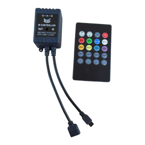
DERUN LIGHTING TECHNOLOGY DR-CON-IR20M-3CH-LV user manual
Prior Scientific
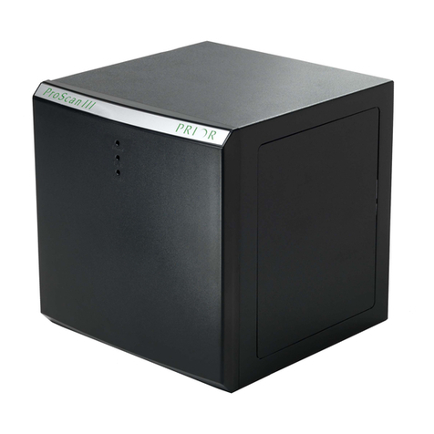
Prior Scientific ProScan III manual

