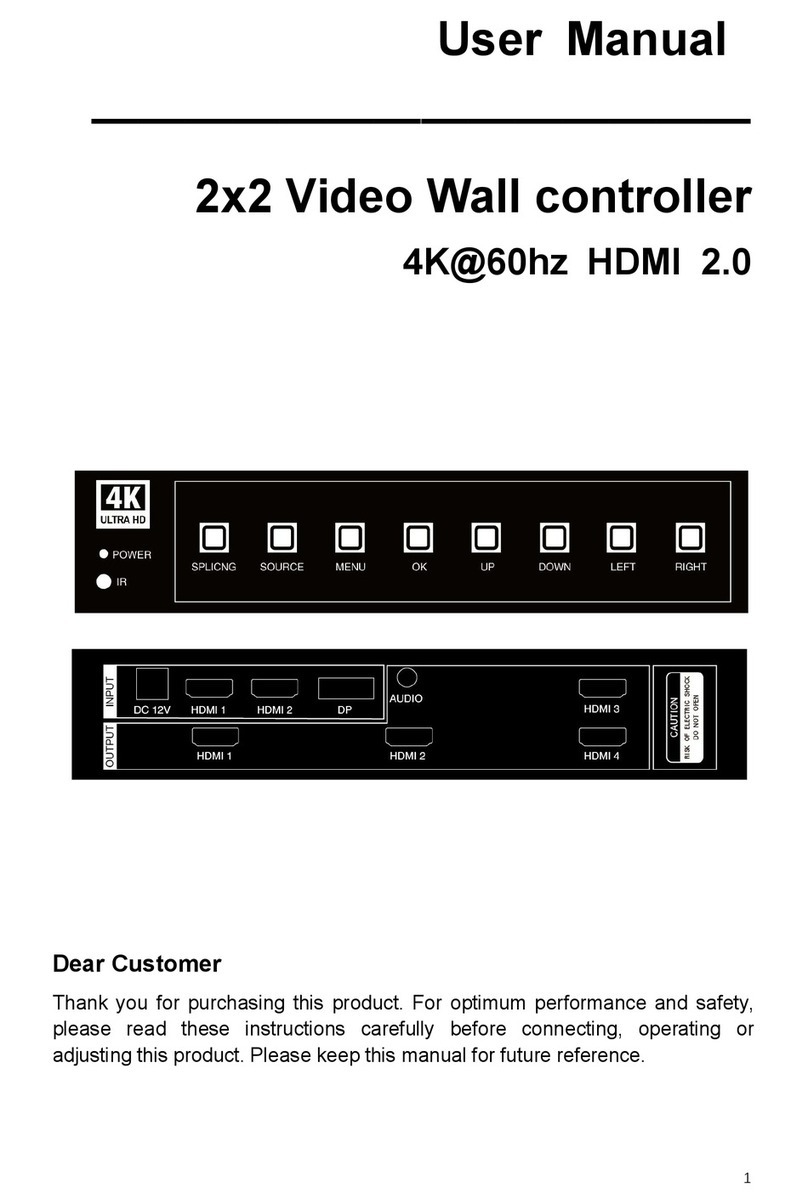
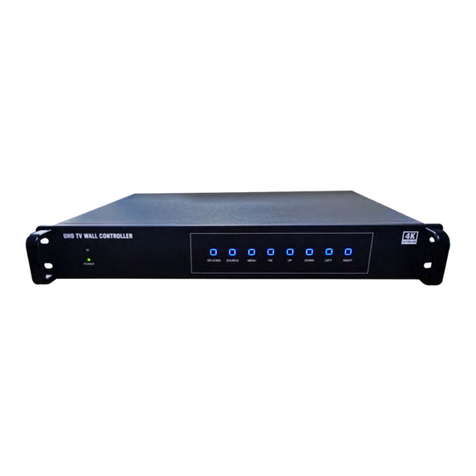
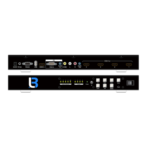
Brightlink 4U User manual


I
Preface
Thank you for purchasing our splicing controllers, the company's products has been carried
out strict safety testing before leaving the factory, to ensure safe operation, as well as prevent the
risk of electric shock. "Splicing Controller User Manual" provide operational guidance for your
device installation and use, to ensure that the product can be safe and trouble-free operation,
please read the User Manual carefully before using this product.
This Manual is applicable to the following products:
Product
Function
Stitching Controller
This product is suitable for splicing and image display
processing of LCD, DLP, LED and other display systems.
Instructions for this Manual:
Thank you for using our splicing controller products, in order to facilitate your use, read the
User Manual carefully, and follow the steps to operate; contact us at any time if you
encounter any problems in the course of the operation.
The "Splicing Controller User Manual" (hereinafter referred to as “the Manual”) is a manual
for the universal splicing product specification, this Manual introduces use methods of
general series of splicing controllers can be used as a reference for the use of other models of
splicing products.
This Manual is used only as instructions for the user's operation and not for maintenance
service purposes.
We will update the contents of this Manual in accordance with the enhancement of the
features of the product, and will periodically change or update the contents described in this
Manual, and the updated contents will be added to the new version without notice.
This Manual is copyrighted by our company, and no unit or individual may use the contents
of this Manual for commercial purposes without permission. The device diagram and
drawing content provided in this Manual only provide reference guidance for users, do not
guarantee that it is in full conformity with the object, please take the physical as the subject.
Attention: Please read the relevant contents of this Manual carefully before using this
device, to avoid possible device damage and personnel injury before installing and using
the device.

II
Relevant conventions about this Manual:
In this Manual, if there are no special instructions, the products or splicing controllers
mentioned refer to the splicing controller products described in this Manual. This Manual uses the
following signs to indicate what should be noted in the operation process and the relevant
instructions, the meaning of these signs are as follows::
Symbol
Description
Electric shock
protection
Indicate a high pressure hazard.
Warning
Indicate a moderate or low potential risk that, if not avoided, may
result in minor or moderate injury to the person.
Danger
Indicate a high potential risk , it may result in loss of life or serious
injury if not avoided.
Attention
Indicate what should be noted in the reminder operation, such as
operational errors that can cause device damage or other undesirable
consequences.
Anti-static
Indicate electrostatic sensitivity device.
Note
Represents the necessary additions and descriptions to the description
of the operation content.
注意 Attention:The contents of the above icons described and prompted do not represent the only
content that the device needs to be prompted or valued, please subject to the specific contents
of the product.

III
Important Safety Tips
In order to ensure the reliable use of device and the safety of personnel, please observe the
following in the installation, use and maintenance:
①
The system must have a perfect grounding, otherwise not only cause signal interference,
instability or mechanical damage, but also may cause personal accidents due to leakage of
electricity.
The final pick-up location of the splicing controller should be connected to the true ground, and its
grounding resistance should be less than 5 Omega.
②
It is prohibited to change the mechanical and electrical design of this product and to prohibit the
addition of any parts, otherwise the manufacturer is not responsible for the harmful results caused
by this.
③
Do not use two-core plugs to ensure that the input power supply of the device is 220V 50/60hz
AC.
④
There are AC 220V high pressure components in the machine, do not open the chassis without
permission, to avoid the risk of electric shock.
⑤
Do not place system device where it is too cold or overheated.
⑥
The power supply of the device will heat up at work, so keep the working environment well
ventilated so as not to damage the machine when the temperature is too high.
⑦
When rainy and humid weather or when not in use for a long time, the power supply gate of the
device should be turned off.
⑧
Be sure to unplug the device's AC power cord from the AC power outlet before doing the
following:
Remove or reload any part of the device
Disconnect or reconnect any electrical plugs or other connections to the device
⑨
Non-professionals without permission, please do not attempt to disassemble the device chassis, do
not privately repair, in order to avoid accidents.
⑩
Do not sprinkle any chemicals or liquids on or near the device.

IV
Content
PREFACE.............................................................................................................................................I
IMPORTANT SAFETY TIPS............................................................................................................III
CHAPTER 1 PRODUCT OVERVIEW..............................................................................................1
1.1 BRIEF INTRODUCTION OF PRODUCT.............................................................................................. 1
1.2 PRODUCT TECHNICAL FEATURES.................................................................................................. 1
1.3 PRODUCT STRUCTURE DIAGRAM...................................................................................................... 3
CHAPTER 2 PRODUCT CHASSIS SPECIFICATION....................................................................5
2.1 PRODUCT CASE SPECIFICATION................................................................................................5
2.2 DIAGRAM OF THE PRODUCT BACK PANEL -4U........................................................................5
2.3 DIAGRAM OF THE PRODUCT BACK PANEL -8U........................................................................6
2.4 DIAGRAM OF THE PRODUCT BACK PANEL -16U......................................................................7
2.5 DIAGRAM OF THE PRODUCT BACK PANEL -24U......................................................................8
2.6 DIAGRAM OF THE PRODUCT BACK PANEL - 36U DUAL.......................................................... 9
CHAPTER 3 PRODUCT PACKING LIST.................................................................................10
CHAPTER 4 PRODUCT INSTALLATION.................................................................................... 11
4.1 INSTALLATION PRECAUTIONS......................................................................................................... 11
4.2 INSTALLATION STEPS.................................................................................................................... 13
CHAPTER 5 PRODUCT CONNECTION...................................................................................... 13
5.1 INPUT AND OUTPUT INTERFACE...................................................................................................13
5.2 POWER CORD CONNECTION........................................................................................................ 13
5.3 COMMUNICATION AND CONNECTION METHODS............................................................................. 14
5.4 CONNECTION TO THE SIGNAL SOURCE........................................................................................16
CHAPTER 6 FRONT PANEL DESCRIPTION............................................................................19
6.1 KEYS DESCRIPTION....................................................................................................................... 19
6.2 SCENE KEYS.................................................................................................................................. 20
CHAPTER 7 REMOTE CONTROL (OPTIONAL DEVICE) DESCRIPTION..................... 21
CHAPTER 8 PRODUCT COMMUNICATION PROTOCOL................................................. 22
APPENDIX I COMMON TROUBLESHOOTING.........................................................................24
APPENDIX 2 SPECIFICATION PARAMETERS.......................................................................... 26
2-1, SYSTEM PARAMETERS.................................................................................................................26
2-2, MODULE PARAMETERS............................................................................................................... 28

1
Chapter 1 Product Overview
1.1 Brief introduction of product
This series of splicing controllers are powerful high-end image processing device, can
display multiple dynamic images on multiple display terminals at the same time, and are mainly
used for large screen mosaic display environment; they are the core display control device of the
system.
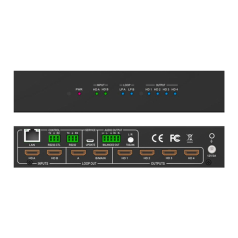
Figure 1-1 4U front panel diagram
Splicing processor is suitable for the stability, security, concentration has a high demand for
places, can be widely used in a variety of applications, for government agencies, transportation
control, security monitoring, public safety, education and scientific research, news media, energy
and other fields to bring a large screen display control solutions.
Support a variety of control methods, including panel keys, RS232 serial port, network,
central control, mobile visual control, etc., to meet the user's various control needs.
1.2 Product technical features
Adopt all-hardware integrated design and have no computer modules; any crashes, power
outages, crashes and other undesirable phenomena will not appear;

2
Adopt modular structure; input module, output module, control module, etc. are supported by
hot-swappable; the board card can be arbitrarily plugged and replaced in the operating state,
convenient for system upgrade and maintenance;
Adopt standard chassis structure design, with 2U, 4U, 8U, 16U, 24U, 36U and other optional
chassis specifications; special specifications of device can be developed, easy to configure.
Support VGA, DVI, HDMI, SDI, CVBS, YPBPR, Duallink, DP, HDBaset, Fiber, IPV
multi-signal mixed input and VGA, DVI, HDMI, SDI, CVBS, Fiber, HDBaset and other
signal output;
Support N+1 redundant power supply structure, with a high degree of stability; when the
system occurs failure, emergency measures can be quickly started to ensure the safe and
stable operation of the system;
Support Ultra HD input, support resolution 4K, 2560x1600@60hz, 1920x1200@60hz and a
variety of standard signal access; the system can be compatible downward and input
resolution can be customized;
All accessed signal windows can be arbitrarily moved, zoomed, displayed in multiple screens,
switched, overlapped within the display range; moreover, a variety of split screen, full screen,
composite screen display modes can also be arbitrarily developed;
Support any output channel at the same time display 1/4/6/8/9/12/16 any format of the signal
window, and the different window levels within the unit can be changed and scaled at will,
can also be dragged to other display screen operation, not limited and affected;
Support output grouping; support up to 8 grouping modes, support screen group resolution
customization, for providing convenience for multi-screen group centralized management
and independent operation;
Support signal replication function, which can infinitely copy signal and arbitrary drag
scaling, with functions of matrix switching and realizing single-screen image segmentation;
Support visual backplane information management, which can uniformly manage and set the
input and output ports and packet information, freely configure output combination;
Support 4K input and output;
Support IP decoding, and the supporting device is equipped with professional IP decoding
card, single channel can open up to 2-way 1080p@60 Hz nine-segmentation window, single
3
card decoding capability: 1080P@30HZ*36; the supporting front end is accessed in RTSP,
GB/T 28181 mainstream IPC protocol; support a variety of video conferencing system SIP,
H.323 protocol;
Support software full-screen pre-monitoring echo function, which can visualize the input
signal management, the current display status of the system can be viewed through the
software interface ;
Support arbitrary adjustment of the display mode, position, window size and layout of the
window;
Support signal window naming, fast positioning, split-screen management mode and many
other operations;
Support multi-level user rights management, which can divide the main administrator,
auxiliary administrator, operator and other rights division mode. Develop zoning
management module, classification, decentralized management;
Support pre-arranged planning management, scene visualization, input pre-monitoring,
output echo, virtual pre-layout and other display modes, easy to achieve multi-scene layout
call requirements;
Mobile visual management, support window adjustment, switching, dragging and cloud
Platform, volume, switch and other intelligent central control applications based on
Windows/Android/IOS and other mobile visual touch platform applications,;
Support any scene call, supports no less than 256 scene modes; the input signals in many
formats are saved into multiple mode scenes, and any calls can be made;
Support CS/BS architecture control function, enable to log into the control server through the
Web browser for remote operation, so that the operation of the system, management,
interface, display can be fully visualized;
Support a variety of control methods; support RS232 serial port, network, panel keys, remote
control, keyboard, central control, mobile end control;
1.3 Product structure diagram
Splicing control system is mainly composed of signal source, controller host, control end and

4
display device, a variety of front-end signal sources including DVI, Dual link, DVI, VGA, Ypbpr,
HDMI, SDI, CVBS, HDBaseT, Optical Fiber and others, they are plugged into the splicing
controllers through the corresponding input board card, and connected to the corresponding
display devices (including DLP splicing, LCD splicing, LED and other display devices ) through
the output end, to realize image arbitrary movement, scaling, roaming, superposition, multi-screen
and other display functions. The control end uses the corresponding control device to carry on the
effective management and control to the whole system.
Figure 1-2 Splicing controller system diagram
Note: The above system connection diagram is the general connection of the product, does
not mean that the products provided have the above signal input, output type and display
function, please take the purchased products prevail.

5
Chapter 2 Product Chassis Specification
2.1 Product Case Specification
Case
Specification
No. of slots
Interface quantity
PC/HDMI
CVBS input
4U
Input ×4
Output ×4
16/16
32
8U
Input ×9
Output ×8
36/32
72
16U
Input ×20
Output ×20
80/80
160
Input ×29
Output ×15
116/60
232
Input ×15
Output ×29
60/116
120
24U
Input ×40
Output ×40
160/160
320
36U Dual
Input ×80
Output ×80
320/320
640
2.2 Diagram of the Product Back Panel -4U
Figure 2-2 Schematic drawing of rear panel -4U

6
2.3 Diagram of the Product Back Panel -8U
Figure 2-3 Schematic drawing of rear panel -8U

7
2.4 Diagram of the Product Back Panel -16U
Figure 2-4 Schematic drawing of rear panel -16U

8
2.5 Diagram of the Product Back Panel -24U
Figure 2-5 Schematic drawing of rear panel -24U

9
2.6 Diagram of the Product Back Panel - 36U Dual
Figure 2-6 Diagram of the Back Panel - 36U
Note: The above product diagrams are not the structural diagrams of the non-standard
equipment, and please refer to the actual products ordered.

10
Chapter 3 Product Packing List
LED Splicing Controller Host
RS232 communication connecting line
Equipment power cords
USB for management software
User manual, warranty card and quality certificate
Notice: The product packing list is the list of general product equipment, which varies
slightly according to the product and interface requirements, and if any missing or
damaged parts are found. Please timely contact the distributor.

11
Chapter 4 Product Installation
4.1 Installation precautions
To avoid damage to the device during installation, please read the installation instructions
carefully before installing the device, including, but not limited to, the following security
considerations:
Warning:
This product is electronic device; pay attention to water, electricity and other humid
environment when using; incorrect operation may cause personnel injury.
General safety tips:
Keep the installation environment clean and dust-free, do not place the device in a damp
place, do not let the liquid immersed in the inside of the device, to avoid causing damage to
the device;
Ensure that the installation of the device location is flat, device placement and installation
location to be firm and reliable, to avoid device installation is not firmly off injury;
Do not place heavy loads on the device, which may cause damage to the device and affect
normal use;
Safety tips for using electricity:
Check to see if there is a potential risk of electric shock in the installation location of the
device, such as whether the device is powered off and whether there is a wet environment
around the device;
Before handling the device, make sure that the outer cable of the chassis has been removed,
including the power cord, serial line, signal cable, etc.
Good grounding should be ensured during device installation process, in order to ensure a
good transfer of electrostatic device;
Safety tips for handling:
Ensure that many people (not less than 2 people) cooperate with the handling device to

12
facilitate the safe movement of the device;
The persons need to maintain consistent work steps when they are handling the device,
remember not to be too fast or too slow to ensure the balance of the body, as well as avoid
damage caused by the fall of device;
Remember to take device in the installation process lightly, to prevent damage to the surface
of the device and internal components, resulting in damage to the device;
Environmental safety tips:
To ensure the long-term stable operation of the device, extend the service life, please
maintain the device at a certain temperature and humidity, the working environment of the
device should be maintained between the -15℃-60℃;
Device should be placed in fresh air, without no excessive dust in the environment; too much
dust entry will affect the normal use of device and the service life of the system;
Device should be installed in a better ventilation environment, to avoid temperature
overheating caused by device damage, affecting the normal use;
Attention :Product installation considerations include, but are not limited to, the above
instructions, please take the actual use of the site requirements prevail.

13
4.2 Installation steps
The splicing controller can be installed on any standard rack; consider the installation and
implementation environment of the device during installation; the installation steps are as follows:
1) Place the device host smoothly on top of the mounting rack to ensure that it does not slide
or fall off.
2) Align the mounting hole positions of the device with the mounting hole positions of the
rack, to ensure that the installation rack of the device does not shift.
3) Fasten the device to the rack and complete the installation of the device by using the
fastening screws, to align the mounting holes one by one.
Chapter 5 Product Connection
5.1 Input and Output interface
According to the number of different input and output signals and interface requirements, this
series splicing controller can be arbitrarily developed a combination. Among them, the input
interface supports Duallink HD video signal, HDMI HD signal, VGA/DVI signal, CVBS
Composite video and YPbPr component signal, and also supports HDBaseT input, fiber fiber input,
with IPV input decoding function.
The output supports HDMI HD signal, VGA/DVI signal and others, can be configured
according to specific requirements. Specific interface terminals can refer to the Chassis screen
printing chart, please consult my company's technical department if you have doubts.
5.2 Power Cord Connection
Please accurately connect one end of the randomly supplied power cord to the device power
jack, and the other end is connected to the power outlet, as shown in the following figure:

14
Figure 5-1 Device Connection diagram
Warning:The power supply system needs to be well grounded to determine the location of
the power supply switch of the device, so that in the event of an accident, the power supply
can be cut off in time.
5.3 Communication and connection methods
The splicing controller provides a standard serial communication port as well as a network
port, in addition to using the front panel keys for arbitrary switching operations, but also allows
users to use a variety of control systems (such as personal computers, central control, etc.) to
control the system.
1) Connect to the control device
1) The splicing controller provides a standard RS-232 serial communication port that allows
users to control using a variety of remote control devices. The RS-232 port is a 9-pin male
connector, and the pins are described as follows:
Needl
e No.
Pin
Description
1
NC
null
2
TXD
Signal sending end, receiving end of the control
device (RXD end)
3
RXD
Signal receiving end, transmission end of the
control device (TXD end)
4
NC
null
Equipment power interface
Power outlet

15
5
GND
Signal ground
6
NC
null
7
NC
null
8
NC
null
9
NC
null
Figure 5-2 9HDF Pin description
2) Connect to the control computer
Using the RS-232 cable to connect the computer's serial communication port (COM1 or
COM2) with the RS-232 communication port of the mosaic, the computer can be controlled by the
splicing controller.
When the splicing controller RS-232 port is connected to the computer, you should pay
attention to the line order of TXD and RXD, as shown in the following figure:
Figure 5-3 communication line structure diagram
If you need to use RS-422 port, please explain to the factory at the time of ordering, the
factory provides RS-422 adapter, at this time the RS-232 port can still be used, but at this time
RS-232 wiring, to exchange lines 2 and 3.
Note:Please use the original RS232 control line to connect the device to control the serial
port.
Splicing controller
Computer
This manual suits for next models
4
Table of contents
Other Brightlink Controllers manuals

Brightlink
Brightlink BL-VW37-4K User manual

Brightlink
Brightlink BL-VW22-4K30 User manual

Brightlink
Brightlink BL-VW22-4K60 User manual

Brightlink
Brightlink BL-VW33-4K60-GUI User manual

Brightlink
Brightlink BL-VW22 User manual

Brightlink
Brightlink BL-VW33-4K User manual

Brightlink
Brightlink BL-VW22-4K60-GUI User manual
Popular Controllers manuals by other brands

CTEK
CTEK Z45 Series user manual

HOMBLI
HOMBLI Smart Water Controller manual

Marshall Excelsior
Marshall Excelsior MEC MEGR-167CH instruction manual

Daktronics
Daktronics ALL-SPORT 5000 Setup instructions

CYP
CYP CDPS-IRL Operation manual

Rauland-Borg
Rauland-Borg MRC7601 Installation, programming and operation instructions