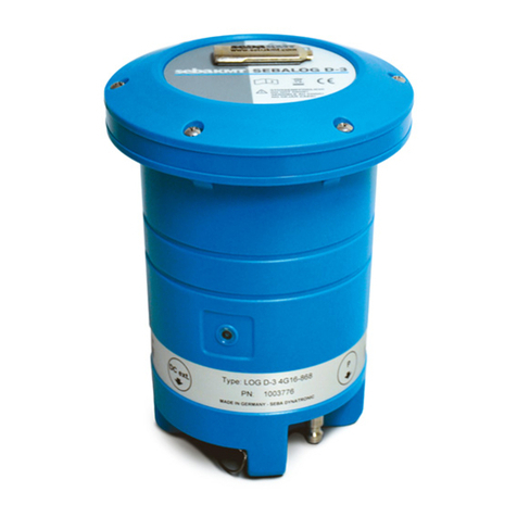
sebaKMT Sebalog D User manual

Mess- und Ortungstechnik
Measuring and Locating Technologies
Leitungsortung
Line Locating
Rohrleitungsnetze
Water Networks
Kommunikationsnetze
Communication Networks
Elektrizitätsnetze
Power Networks
Issue: 1(09/2008)
5 V
Alarm IN
Operating Instructions
Data Logger
Sebalog D


1-3
Consultation with SebaKMT
The present system manual has been designed as an operating guide and for reference. It is meant to answer your
questions and solve your problems in as fast and easy a way as possible. Please start with referring to this manual
should any trouble occur.
In doing so, make use of the table of contents and read the relevant paragraph with great attention. Furthermore,
check all terminals and connections of the instruments involved.
Should any question remain unanswered, please contact:
Seba Dynatronic
Mess- und Ortungstechnik GmbH
Hagenuk KMT
Kabelmesstechnik GmbH
Dr.-Herbert-Iann-Str. 6
D - 96148 Baunach
Phone: +49 / 9544 / 68 – 0
Fax: +49 / 9544 / 22 73
Röderaue 41
D - 01471 Radeburg / Dresden
Phone: +49 / 35208 / 84 – 0
Fax: +49 / 35208 / 84 249
http://www.sebakmt.com
SebaKMT
All rights reserved. No part of this handbook may be copied by photographic or other means unless SebaKMT have before-hand
declared their consent in writing. The content of this handbook is subject to change without notice. SebaKMT cannot be made
liable for technical or printing errors or shortcomings of this handbook. SebaKMT also disclaim all responsibility
for damage resulting directly or indirectly from the delivery, supply, or use of this matter.

1-4
Terms of Warranty
SebaKMT accept responsibility for a claim under warranty brought forward by a customer for a product sold by
SebaKMT under the terms stated below.
SebaKMT warrant that at the time of delivery SebaKMT products are free from manufacturing or material defects
which might considerably reduce their value or usability. This warranty does not apply to faults in the software
supplied. During the period of warranty, SebaKMT agree to repair faulty parts or replace them with new parts or
parts as new (with the same usability and life as new parts) according to their choice.
SebaKMT reject all further claims under warranty, in particular those from consequential damage. Each component
and product replaced in accordance with this warranty becomes the property of SebaKMT.
All warranty claims versus SebaKMT are hereby limited to a period of 12 months from the date of delivery. Each
component supplied by SebaKMT within the context of warranty will also be covered by this warranty for the
remaining period of time but for 90 days at least.
Each measure to remedy a claim under warranty shall exclusively be carried out by SebaKMT or an authorized
service station.
To register a claim under the provisions of this warranty, the customer has to complain about the defect, in case of
an immediately detectable fault within 10 days from the date of delivery.
This warranty does not apply to any fault or damage caused by exposing a product to conditions not in accordance
with its specification, by storing, transporting, or using it improperly, or having it serviced or installed by a workshop
not authorized by SebaKMT. All responsibility is disclaimed for damage due to wear, will of God, or connection to
foreign components.
For damage resulting from a violation of their duty to repair or re-supply items, SebaKMT can be made liable only
in case of severe negligence or intention. Any liability for slight negligence is disclaimed.

1-5
Contents
1Safety Advices..................................................................................................................1-7
2Technical Description......................................................................................................2-8
2.1
Technical Data ..................................................................................................................... 2-8
2.2
Scope of Delivery ................................................................................................................. 2-9
2.3
Available Configurations....................................................................................................... 2-9
2.4
Design ................................................................................................................................ 2-11
2.5
Accessories........................................................................................................................ 2-13
3Commissioning the Logger...........................................................................................3-14
3.1
Configuring the Logger....................................................................................................... 3-14
3.2
Preparing the Logger for GSM Connectivity....................................................................... 3-14
3.3
Connecting the Logger....................................................................................................... 3-16
3.3.1
Connecting Sensors and Alarm Devices.................................................................... 3-16
3.3.1.1
Basics ................................................................................................................................. 3-16
3.3.1.2
Connection Equipment for Single-channel Loggers........................................................... 3-18
3.3.1.3
Connection Equipment for Multi-channel Loggers ............................................................. 3-19
3.3.1.4
Wiring Diagram Examples.................................................................................................. 3-21
3.3.2
Connecting a Tube to an Internal Pressure Sensor................................................... 3-25
3.4
Commissioning the Logger................................................................................................. 3-26
3.4.1
Positioning the Logger ............................................................................................... 3-26
3.5
Positioning the GSM Antenna ............................................................................................ 3-26
3.6
Switching the Logger On/Off .............................................................................................. 3-27
4Setting Up the Software.................................................................................................4-28
4.1
System Requirements........................................................................................................ 4-28
4.2
Installing the Software........................................................................................................ 4-28
4.3
Connecting the Logger to the PC....................................................................................... 4-29
4.3.1
Radio Communication via E-Box ............................................................................... 4-29
4.3.2
Connecting the Logger via Direct Connection............................................................ 4-30
4.4
Starting the Software.......................................................................................................... 4-31
4.5
Registering a Logger.......................................................................................................... 4-32
4.5.1
Adding / Deleting a Logger......................................................................................... 4-32
4.5.2
Adding / Deleting a Group.......................................................................................... 4-33
5Configuring the Logger.................................................................................................5-35
5.1
Selecting the Logging Interval............................................................................................ 5-36
5.2
Sensor Configuration.......................................................................................................... 5-36
5.2.1
Sensor Type............................................................................................................... 5-37

1-6
5.2.1.1
Configuring a „Customer Specific“ Sensor .........................................................................5-37
5.2.1.2
Input Type Examples..........................................................................................................5-38
5.2.2
Configuring Alarm Conditions (Threshold Monitoring)................................................5-40
5.2.3
Finishing the Configuration.........................................................................................5-41
5.3
Configuring the Switching Inputs (Alarm Inputs)................................................................. 5-42
5.4
Configuring the Radio Communication...............................................................................5-44
5.4.1
SIM Card Configuration..............................................................................................5-46
5.4.2
Configuring the Internet Access Point of the Network Operator................................. 5-46
5.4.3
Email Configuration....................................................................................................5-46
5.4.4
FTP Settings............................................................................................................... 5-47
5.4.5
SMS Destinations.......................................................................................................5-47
5.4.6
Summary Messages...................................................................................................5-47
5.4.7
Testing the GSM Settings ..........................................................................................5-48
5.4.7.1
Testing SMS / Email Transmission.....................................................................................5-48
5.4.7.2
Testing FTP Data Transfer .................................................................................................5-50
5.4.8
Finishing the Communication Setup...........................................................................5-50
5.5
Start Time...........................................................................................................................5-50
5.6
Memory Mode.....................................................................................................................5-51
5.7
State ...................................................................................................................................5-51
5.8
Finishing the Configuration.................................................................................................5-51
6Retrieving and Evaluating Data.....................................................................................6-52
6.1
Retrieving Data from the Logger.........................................................................................6-52
6.2
Collecting Data from the FTP Server..................................................................................6-53
6.3
Evaluating Measured Data .................................................................................................6-54
7Miscellaneous Functions...............................................................................................7-56
7.1
Identifying Loggers .............................................................................................................7-56
7.2
Real-Time Measurement....................................................................................................7-56
7.3
Setting the Clock.................................................................................................................7-57
7.4
CSV Export.........................................................................................................................7-57
7.5
Deleting Logged Data.........................................................................................................7-57
7.6
Firmware.............................................................................................................................7-58
8Replacing the Batteries..................................................................................................8-59

1-7
1 Safety Advices
Safety precautions
This manual contains basic advice for the installation and operation of the Sebalog D.
It is essential to make this manual accessible to the authorized and skilled operator.
He needs to read this manual closely. The manufacturer is not liable for damage to
material or humans due to non-observance of the instructions and safety advices
provided by this manual.
Locally applying regulations must be observed.
Special transportation
requirements
The lithium batteries of the Sebalog D are dangerous goods. The transport of the
batteries itself and of devices which contain such batteries is subject to regulations
based on the UN Model Regulations “Transport of Dangerous Goods”
(ST/SG/AC.10-1).
Please inform yourself about the transportation requirements and follow them when
shipping the device.
General Cautions
•
The limits described under technical data may not be exceeded.
•
Do not drop the device or subject it to strong impacts or mechanical shocks!
•
Do not operate the device with a voltage unequal to the specified operating voltage!
•
Original accessories ensure safe operation of the equipment. It is not allowed and
the warranty is lost if other accessories than the original ones are used with the
equipment.
•
Cover the sockets on the top of the device always with the provided protection caps
,
if no cable is connected to the terminal. Otherwise, penetrating dirt and water may
damage the device.
CAUTION
!

2-8
2 Technical Description
Intended application
The Sebalog D is a compact, robust and extremely versatile data logger. The device
can record the readings of various sensor types in user-defined intervals. The
collected data can be periodically transmitted to a FTP server or read out with a PC or
special equipment.
Depending on the configuration of the logger, up to 4 freely programmable channels
can be connected to sensors for data recording.
Furthermore, the logger can be used to trigger user-defined alarm signals (e.g. signal
lights, SMS or email), if a threshold is exceeded or special alarm equipment is
triggered.
2.1 Technical Data
Depending on the configuration, the Sebalog D is specified by the following
parameters:
Parameter Value
Communication USB interface
Wireless, 868/915 MHz
GSM/GPRS modem, 850/900/1800/1900 MHz
Inputs / outputs
1, 2 or 4 freely programmable channels, analog or digital
(0…5 V / 0…20 mA / pulse / frequency)
up to 2 switching inputs (alarm trigger)
up to 2 switching outputs (alarm installation)
up to 2 connectors for internal pressure sensors
Internal pressure
sensors up to 2 sensors (optional)
(10 bar / 16 bar / 25 bar / 40 bar)
Accuracy +/- 0,1%
Interval 1 s … 31 days (programmable)
Memory
2 MByte internal memory (expandable via SD)
Block or roll memory
Alarm - switching input(s) and threshold monitoring
- triggering of switching output(s) and SMS / email
notifocation
Operating voltage 12 V DC
Accumulator Internal lithium battery
Operating
temperature -10°C … +50°C
Dimensions
(L x W x H) 115 x 115 x 180 mm
Weight 0,8 kg
Protection class IP 68

2-9
2.2 Scope of Delivery
Besides of the logger unit and a magnet, the Sebalog D package contains a CD with
the following content:
•SebaDataView configuration and readout software
•Driver
•Sebalog D information materials
Depending on the configuration of the logger, the scope of delivery may contain even
more accessories which can also be ordered from SebaKMT (see section 2.5).
2.3 Available Configurations
Introduction
The Sebalog D is available in a wide variety of configurations. It ranges from a basic
version with 1 channel to a full equipped version with 4 channels, integrated pressure
sensors and an internal GSM modem.
The feature options can be combined in almost any possible way which leads to the
many configurations listed in the table below. By means of the item number (PN) on
the bottom of the logger you can identify the type of your device:
Single-channel versions
Item number Type Item number Type
820013543 LOG D1-B 820013549 LOG D1-GSM-P1-16
820013544 LOG D1-P1-16 820013550 LOG D1-GSM-P1-25
820013545 LOG D1-P1-25 820013551 LOG D1-GSM-P1-40
820013546 LOG D1-P1-40 820013552 LOG D1-I-B
820013547 LOG D1-GSM 820013559 LOG D1-I-GSM
2-channel versions
Item number Type Item number Type
820013506 LOG D2-B 820013522 LOG D2-GSM-P2-16
820013507 LOG D2-P1-16 820013523 LOG D2-GSM-P2-25
820013508 LOG D2-P1-25 820013525 LOG D2-GSM-P2-40
820013510 LOG D2-P1-40 820013527 LOG D2-I-B
820013512 LOG D2-P2-16 820013530 LOG D2-I-P1-16
820013515 LOG D2-P2-25 820013531 LOG D2-I-P1-25
820013516 LOG D2-P2-40 820013532 LOG D2-I-P1-40
820013518 LOG D2-GSM 820013536 LOG D2-I-GSM
820013519 LOG D2-GSM-P1-16 820013537 LOG D2-I-GSM-P1-16
820013520 LOG D2-GSM-P1-25 820013538 LOG D2-I-GSM-P1-25
820013521 LOG D2-GSM-P1-40 820013539 LOG D2-I-GSM-P1-40

2-10
4-channel versions
Item number Type Item number Type
820012348 LOG D4-B 820012354 LOG D4-I-B
820012349 LOG D4-P1-16 820012355 LOG D4-I-P1-16
820013478 LOG D4-P1-25 820013487 LOG D4-I-P1-25
820013479 LOG D4-P1-40 820013488 LOG D4-I-P1-40
820012350 LOG D4-P2-16 820012356 LOG D4-I-P2-16
820013480 LOG D4-P2-25 820013489 LOG D4-I-P2-25
820013481 LOG D4-P2-40 820013490 LOG D4-I-P2-40
820012351 LOG D4-GSM 820012357 LOG D4-I-GSM
820012352 LOG D4-GSM-P1-16 820012358 LOG D4-I-GSM-P1-16
820013482 LOG D4-GSM-P1-25 820013491 LOG D4-I-GSM-P1-25
820013483 LOG D4-GSM-P1-40 820013492 LOG D4-I-GSM-P1-40
820012353 LOG D4-GSM-P2-16 820012359 LOG D4-I-GSM-P2-16
820013485 LOG D4-GSM-P2-25 820013474 LOG D4-I-GSM-P2-25
820013486 LOG D4-GSM-P2-40 820013493 LOG D4-I-GSM-P2-40
Type number
The type number consists of the following segments:
Due to the large amount of possible configurations, this manual cannot state
explicitly whether or not a described function applies to your device. Please use
the information provided within this section to identify the specific capabilities of
your logger.
10 … The internal pressure sensors have a measuring
range of 10 bar
16 … The internal pressure sensors have a measuring
range of 16 bar
25 … The internal pressure sensors have a measuring
range of 25 bar
40 … The internal pressure sensors have a measuring
range of 40 bar
LOG D4
-
I
-
GSM
-
P2
-
16
D1 … the logger has 1 logging channel
D2 … the logger has 2 logging channels
D4 … the logger has 4 logging channels
The logger can be connected to a sensor via current loop
the logger contains an internal GSM modem
P1 …the logger contains one internal pressure sensor
P2 …the logger contains two internal pressure sensors

2-11
2.4 Design
Controls and indicators
The following figure shows all the front panel operating controls and indicators. The unit
is in protection class IP 68:
The Sebalog D consists of the following operating controls and indicators:
Item Description
On/off contact area
I/O control lamp
not lit: Logger is switched off
green (flashing): Logger is switched on and in energy saving mode
green (permanent): Logger is switched on and a radio link to a
PC (E-Box) is established
orange (permanent): Data transfer takes place
red (for a moment): Logger is switching off
1
2
1
2

2-12
Connectors
The following figure shows the connectors of the Sebalog D which are placed on top of
the device. While the USB socket is always part of the assembly, it depends on the
configuration of the logger whether the other connectors are existent:
The Sebalog D offers the following connectors:
Item Description
IN socket
USB / DC ext. socket
internal pressure sensor P1
internal pressure sensor P2
GSM antenna socket
4
7
6
5
3
5
3
4
6
7

2-13
2.5 Accessories
In addition to the standard scope of delivery, there is a large amount of optional
accessory parts which can be ordered from SebaKMT.
The following table describes all available accessory parts:
Accessory part Description Item number
Connection cable
VK 75, green - for connecting the logger to up to 4
sensors
- must be connected to the
IN socket
820012449
Connection cable
VK 76, red - for connecting a sensor and up to 2
switching inputs / outputs (alarming)
- must be connected to the
USB / DC ext. socket
820012450
Connection cable
VK 77 USB, red - for connecting the logger to a PC
- must be connected to the
USB / DC ext. socket
820012451
E-Box USB
Allows wireless data transfer between
the logger and a PC within a range of
about 100 m.
820009270
USB cable (1 m) For connecting the E-Box to the PC 820008969
Antenna for E-Box Spare part 122010014
Reader Box For wireless on-site data readout
without PC on request
GSM antenna with
connection cable (3 m) - only for logger with GSM modem
- must be connected to the
GSM socket
820012452 (cable)
Coupler
(1/4” male thread) For connecting a tube with ¼” female
thread to an internal pressure sensor
820014883
AD-21
External pressure sensor
Different measuring ranges available on request
External accumulator External power supply for the logger on request
Charger For charging the external
accumulator (see above) on request
7
3
4
4

3-14
3 Commissioning the Logger
3.1 Configuring the Logger
Prior to its on-site installation, the logger must be properly configured using the
supplied SebaDataView software. In doing so, the logger has to be provided with the
channel allocation, the alarm conditions and the wireless connection parameters
among other things.
(For a detailed description of the logger configuration, please refer to chapter 5).
3.2 Preparing the Logger for GSM Connectivity
If the data collected by the logger should be periodically transferred to a FTP server
or if an alarm notification via email / SMS is required, the following steps must be
performed in order to prepare a logger (with built-in GSM modem) for GSM
connectivity:
Step Action
1 In order to get a SIM card enabled for data transfer via GPRS, you have
to close a suitable contract with a mobile phone service provider.
2 Loosen the four marked screws with a M3 allen key or with a crosstip
screwdriver respectively (depending on the logger type) and remove
the front panel.

3-15
(Continuation from previous page:)
Step Action
Insert the SIM card into the slot as shown in the figure below. The card
has to snap into the spring mechanism.
If you need to release the card, gently press its protruding edge.
3
Please be careful not to damage any electrical parts within the
logger.
Attach the front panel to the housing again.
4
In order to ensure the total protection against water and dust
ingress compliant with IP 68, the following instructions must be
observed:
•If the logger is older then six months and if the front panel has
not been changed during the last six months, a new front panel
including a new rubber seal must be installed. A new front
panel can be ordered from SebaKMT.
•The rubber seal and the contact surfaces of the housing must
be free of dirt.
•Be careful not to jam the housing parts against each other.
•Tighten the screws with a torque of 1 Nm.
5 Connect the supplied GSM antenna with the GSM socket . Make
sure that the guide on the plug fits in the groove in the socket and that
you feel the plug latch in.
6 Make sure that the GSM settings have been properly configured (see
section 5.4).
7
(cut edge to the left)

3-16
3.3 Connecting the Logger
Depending on its configuration, the following peripheral and measring devices can be
connected to a logger:
•up to 4 sensors can be attached and the data can be logged (e.g. pressure,
flow velocity)
•up to 2 alarm-triggering devices (e.g. a light barrier) can be connected to the
switching inputs
•up to 2 devices (e.g. signal lamp, pump) can be connected to the switching
outputs and can be triggered in the case of an alarm
•up to two tubes can be directly connected to the internal pressure sensors
Depending on the type of sensors / alarm devices connected to the Sebalog D, the
appropriate parameter values have to be provided to the logger using the
SebaDataView software. For a detailed description of the necessary configuration
steps, please refer to section 5.2.
3.3.1 Connecting Sensors and Alarm Devices
3.3.1.1 Basics
Introduction One end of the VK 75 / VK 76 connection cables used for connecting equipment to
the logger is uncoated and ten colour-coded wires stick out of it. According to its
colour, each of these wires represents a specific input / output of the logger and can
be directly connected to the respective terminal of a peripheral device (e.g. a sensor).
If no adequate terminals are existent, a luster terminal or other accessories can be
used. A proper electrical insulation must be ensured.
For the basic logger version with only one channel, all connections are established
via the VK 76 connection cable attached to the USB / DC ext. socket .
For loggers with 2 or even 4 channels only the switching inputs/outputs and the
external power supply are connected via the VK 76 connection cable. Any
connections to sensors are established via the VK 75 connection cable attached to
the IN socket .
The channels are assigned in numeric order which means that for a 2-channel
logger, the channels 1 and 2 have to be used for the connection setup.
3
4

3-17
Fixed channel allocations Due to the internal wiring of the logger, current loops can only be connected to the
channels 2 and 4.
The internal pressure sensors P1 and P2 are always linked to channel 1 and 3. If the
logger is equipped with one or two internal pressure sensors, the respective channels
are in use and must not be connected to external sensors.
Corresponding to these conventions, the following channel allocations apply:
Channel 1 Channel 2 Channel 3 Channel 4
Single-channel Logger
Int. pressure sensor
X
Current loop
X
2-channel Logger
Int. pressure sensor P1 X
Int. pressure sensor P2 X
Current loop X
4-channel Logger
Int. pressure sensor P1
X
Int. pressure sensor P2
X
First current loop
X
Second current loop
X

3-18
3.3.1.2 Connection Equipment for Single-channel Loggers
Introduction Loggers with only one channel (LOG D-1) can be connected to one sensor, a
switching input and a switching output. All of these connections can be established
with only one connection cable (VK 76) attached to the USB / DC ext. socket .
VK 76 pin assignment in
combination with
single-channel loggers
In combination with a single-channel logger, the VK 76 connection cable has the
following pin assignment:
Wire Description
white Channel +
brown Channel – Channel a sensor can be connected to.
green Switching
input 2 An alarm-triggering device with a voltage output of
0 … 5 V can be connected between this wire and
the purple wire (GND).
yellow Switching
output
(relay 2) OUT
pink Switching
output
(relay 2) IN
An electric circuit with an external DC power supply
up to 12 V / 1 A can be connected between these
two wires. If the internal relay is triggered by an
alarm event, the circuit is closed and the connected
load is activated / triggered.
red External
power supply An external power supply with 12 V DC can be
connected between this wire and the purple wire
(GND). The internal battery cannot be charged by an
external power supply.
purple GND
grey not used
blue not used
black not used
4
red
(to be connected to
USB / DC ext.)

3-19
3.3.1.3 Connection Equipment for Multi-channel Loggers
Introduction Multi-channel loggers are equipped with the additional IN socket up to 4 external
sensors can be connected to (via the VK 75 connection cable). The switching
inputs/outputs and the external power supply have to be connected to the
USB / DC ext. socket (via the VK 76 connection cable).
VK 75 pin assignment In combination with a multi-channel logger, the VK 75 connection cable has the
following pin assignment:
Wire Description
white Channel 1 +
brown Channel 1 –
green Channel 2 +
yellow Channel 2 –
grey Channel 3 +
pink Channel 3 –
blue Channel 4 +
red Channel 4 –
Channels up to 4 sensors can be connected to.
black 5 V OUT
purple GND DC power supply for sensors or other loads
(U = 5 V / I
max
= 20 mA)
4
3
green
(to be connected to IN)

3-20
VK 76 pin assignment in
combination with multi-
channel loggers
In combination with a multi-channel logger, the VK 76 connection cable has the
following pin assignment:
Wire Description
white Switching
Input 1
green Switching
Input 2
An alarm-triggering device with a voltage output of
0 … 5 V can be connected between a switching
input and the purple wire (GND).
brown Switching
output
(relay 1) OUT
yellow Switching
output
(relay 2) OUT
pink Switching
outputs IN
An electric circuit with an external DC power
supply up to 12 V / 1 A can be connected to each
switching output. If an internal relay is triggered by
an alarm event, the respective circuit is closed and
the connected load is activated / triggered.
red
External
power supply An external power supply with 12 V DC can be
connected between this wire and the purple wire
(GND). The internal battery cannot be charged by
an external power supply.
purple GND
grey not used
blue not used
black not used
red
(to be connected to
USB / DC ext.)
Table of contents
Other sebaKMT Data Logger manuals
