In-situ Tube 300R User manual

Owner's Manual
Tube 300R Telemetry System
Part No. 0062000 | 0062010 | 0062120 | 0062130 | 0062020 | 0062140
Information subject to change without notice. In-Situ, In-Situ logo, Baro Merge, BaroTROLL, HERMIT, HydroVu™, iSitu, Pocket-Situ, RDO,
RuggedCable, RuggedReader, SmarTROLL™, TROLL, VuSitu, and Win-Situ are trademarks or registered trademarks of In-Situ Inc.©2016.
All rights reserved.
0061000 | Rev. 003 | 01/2016

800-446-7488
2
www.in-situ.com
Copyright © 2016 by In-Situ All rights reserved.
This document contains proprietary information which is protected by copyright. No part
of this document may be photocopied, reproduced, or translated to another language
without the prior written consent of In-Situ
Mailing and Shipping Address: Phone: 970-498-1500 (international & domestic)
In-Situ
221 East Lincoln Avenue
Fort Collins, CO 80524
U.S.A.
Fax: 970-498-1598
Internet:
www.in-situ.com
Support: 800-446-7488 (U.S.A. & Canada)
In-Situ makes no warranty of any kind with regard to this material, including, but not
limited to, its fitness for a particular application. In-Situ will not be liable for errors
contained herein or for incidental or consequential damages in connection with the
furnishing, performance, or use of this material.
In no event shall In-Situ Inc. be liable for any claim for direct, incidental, or
consequential damages arising out of, or in connection with, the sale, manufacture,
delivery, or use of any product.
In-Situ and the In-Situ logo, Win-Situ, TROLL, Baro Merge, BaroTROLL, HERMIT,
HydroVu™, iSitu, Pocket-Situ, RDO, RuggedCable, RuggedReader, SmarTROLL™,
TROLL, VuSitu™, and Win-Situ are trademarks or registered trademarks of In-Situ Inc.
Microsoft and Windows are registered trademarks of Microsoft Corporation. Pentium is
a registered trademark of Intel. Tefzel and Delrin are registered trademarks of E. I.
DuPont de Nemours and Company. Viton is a registered trademark of DuPont Dow
Elastomers. Kellems is a registered trademark of Hubbell Inc. Alconox is a registered
trademark of Alconox Company. Lime-A-Way is a registered trademark of Reckitt
Benckiser. Android is a trademark of Google Inc. iPod and iPhone are trademarks of
Apple Inc., registered in the U.S. and other countries. The Bluetooth word mark and
logos are registered trademarks owned by the Bluetooth SIG, Inc. and any use of such
marks by In-Situ Inc. is under license. NIST is a registered trademark of the National
Institute of Standards and Technology, U.S.A. Other brand names and trademarks are
property of their respective owners.
The presence of the Waste Electrical and Electronic Equipment (WEEE)
marking on the product indicates that the device is not to be disposed
via the municipal waste collection system of any member state of the
European Union.
For products under the requirement of WEEE directive, please contact
your distributor or local In-Situ office for the proper decontamination
information and take back program, which will facilitate the proper
collection, treatment, recovery, recycling, and safe disposal of the device.
0061000 | Rev. 003

800-446-7488
3
www.in-situ.com
Table of Contents
1 Introduction 5
Unpacking and Inspection 5
Model Number 6
Serial Number 6
Safety 6
General Specifications 7
2 Configuring Your Instruments 7
Overview 7
Connecting an In-Situ Instrument to the Computer 8
Changing Instrument Communication Settings 8
Changing Instrument Communication Settings - TROLL 9500 Only 9
Setting Up a Log 9
3 Configuring the Telemetry Device 9
Overview 9
Opening the Unit 9
Battery 10
Connecting the Tube to the Computer 10
Select Connected Probes 10
Select Probe Parameters for Alarming 11
Set Level Reference 11
Set the Site Name and Clock 12
Configure Options 12
Modem Parameters 13
Activate Alarms 14
Set Probe Reading Schedule 14
Set Wake Up Events 15
Restart Device and Test Communications 15
4 Digital, Pulse, and Analog Input 16
Wiring Diagram 16
Connecting the Tube to the Computer 16
Input Configuration 17
5 Field Installation 18
Deploy the Tube 18
Improving Signal Quality 18
6 Troubleshooting 18
Troubleshooting Common Issues 18

800-446-7488
4
www.in-situ.com
I Can't Connect 18
I Cannot Select Barometric Compensation on my Non-vented Tube 19
Error Codes and Messages 19
Activate the Modem 20
SIM Card 21
SD Card 22
Warranty 22
Obtaining Repair Service 23
7 Appendix - Alarms 23
Alarms - Overview 23
Absolute Mode 24
Incremental Mode 25
Probe Out of Range SMS Alarms in Absolute Mode 26
Probe Out of Range SMS Alarms in Incremental Mode 26

800-446-7488
5
www.in-situ.com
Introduction
This manual is intended to describe the characteristics, operation, and maintenance of
the Tube 300R TelemetrySystem.
Unpacking and Inspection
All Tube 300 Telemetry Systems contain the following items:
lTube 300R unit
lLithium battery pack
lStub antenna
lTube 300R eye bolts (2)
You must supply the following items for setup and installation:
lTube setup/communication cable (part number 0062260)
lIn-Situ instrument and appropriate cable
lTROLL Com Communication Device for connecting your In-Situ instrument to
your computer
lTube 300R in-well bail (optional - part number 0060240) to deploy the Tube
inside of the well casing
lWin-Situ 5 Software* for programming your In-Situ instrument
* Software can be installed from an In-Situ software CD or downloaded from
www.in-situ.com/software
If you did not purchase a SIM card and data plan from In-Situ, you will need these
additional items:
lSIM (subscriber identity module) card
lCellular service plan
Your Tube Telemetry System was carefully inspected before shipping. Inspect the
package for any physical damage sustained during shipment. Notify In-Situ and file a
claim with the carriers involved if there is any damage. Do not attempt to operate the
instrument when damage has occurred.

800-446-7488
6
www.in-situ.com
Model Number
The model number is printed on the product label affixed to the unit body. The model
number states what type of unit you have. Below is an example model number.
T3R-3G-B-1RT
The first set of characters determine the product type. "T3" indicates a Tube and "R"
indicates a non-solar unit.
The second set of characters indicate the type of modem installed. "2G" means a 2nd
generation cellular device, "3G" means a 3rd generation device.
The single character indicates whether the unit is vented (V) or non-vented (B). Non-
vented units have an internal barometric sensor installed.
The final set of characters indicates the instrument connection type. The number equals
the amount of connections. An "RT" following the number means Rugged TROLL
connection, while a "T" means titanium Twist-lock connection.
Therefore, the example model number means the following:
T3R-3G-B-1RT: Tube 300R (non-solar), 3G, non-vented, 1 Rugged TROLL connection
Serial Number
The unit serial number is printed on the product label affixed to the unit body. This
number is important for warranty and service purposes.
Safety
lDo not connect the battery without an antenna installed.
lNever install a battery other than one supplied by In-Situ
lDo not submerge the Tube in liquid.
lWhen deploying the Tube inside a well casing, always use a deployment method
rated for the weight of the Tube and the attached instrument. Failure to do so
may result in the Tube (and its lithium battery pack) falling into the well.

800-446-7488
7
www.in-situ.com
General Specifications
Operating ranges
Temp: -20° to 70° C (-4 to 158° F)
Humidity: 95% max. non-condensing
Diameter, maximum
Tube: 5 cm (1.97 in.)
Top cap: 5.1 cm (2.0 in.)
Dimensions
Length: 48 cm (18.9 in.)
Weight with battery
1730 g (3.81 lbs)
Materials
Stainless steel
Rating
IP68 (cannot operate submerged)
Power
Internal battery
Battery
Lithium 10.8V / 19000 mAh
Instrument compatibility
Aqua TROLL 100/200 Data Logger
Aqua TROLL 400 Multiparameter Instrument
Aqua TROLL 600 Multiparameter Instrument
BaroTROLL Data Logger
Level TROLL 400/500/700/700H Data Loggers
RDO PRO-X Probe
Rugged BaroTROLL Data Logger
Rugged TROLL 200 Data Logger
TROLL 9500 Multiparameter Instrument
Communication
Antenna
GSM quad band—850, 900, 1800, 1900 MHz (GPRS, SMS,
email, FTP); 2G or 3G
SMA connector with stub antenna or optional external
antenna
Sensors
Built-in barometric pressure sensor (non-vented systems
only)
Built-in temperature system
Warranty
1 year from date of shipment
Configuring Your Instruments
Overview
Tube 300R units support a single In-Situ device. You must change communication
settings on your device so it can transmit data to the Tube.
800-446-7488
8
www.in-situ.com
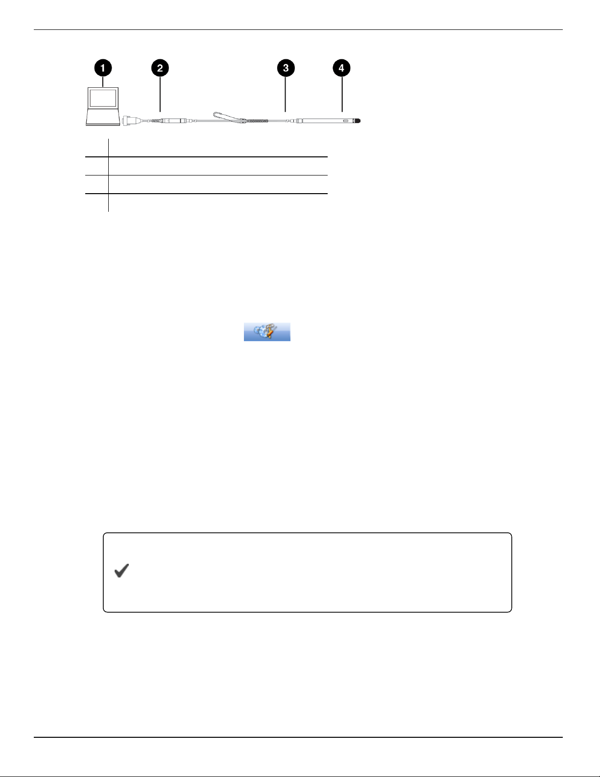
Connecting an In-Situ Instrument to the Computer
1 Laptop or PC
2 TROLL®Com Communication Device*
3 RuggedCable®System**
4 In-Situ instrument
* TROLL Com device may be a USB-connect, serial-connect, or direct-connect** model
** RuggedCable is omitted when using a direct-connect TROLL Com
Changing Instrument Communication Settings
1. Connect to the instrument using Win-Situ 5 software.
2. Click the Device Setup tab .
3. Click Modbus Setup...
4. Select the following options:
Baud: 9600
Data Bits: 8
Parity Bits: None
Stop Bits: 1
End Of Message Timeout (ms): 1000
End of Session Timeout (ms): 5000
Mode: Modbus-ASCII
5. Click the checkmark. Click Yes to change the communication settings. Click Yes or
No to save these settings as the default for Win-Situ 5.
You must change Win-Situ Software communication settings to
match the instrument communication settings next time you
connect the instrument. Change this under Preferences >Comm
Settings.
Set up and start a log in the instrument if you require data redundancy and your
instrument supports internal data logging.

800-446-7488
9
www.in-situ.com
Changing Instrument Communication Settings - TROLL 9500 Only
1. Connect to the instrument using Win-Situ 4 software.
2. Right click the TROLL 9500 device in the tree on the left, and select Edit.
3. Select ASCII Mode Preferences, and click Next.
4. Select the following options:
Comma delimited
Enable ASCII mode of linear tests
5. Click Finish.
For the TROLL 9500 to function, you must set up a log and set the logging interval the
same as the Tube logging interval.
Setting Up a Log
The Tube logs data from instrument directly to the internal SD card. How and when the
data is recorded is configured using the Tube set up tool.
If you require data redundancy, program a log on your instrument prior to connecting it
to the Tube. Some instruments do not support logs.
Refer to your instrument manual for instructions on setting up a log.
Configuring the Telemetry Device
Overview
If you purchased a data plan through In-Situ, you need to open the unit and connect the
battery, and then set up the Tube using the configuration software.
If you are using a 3rd party data plan, you will need to install the SIM card prior to
setting up the Tube with the configuration software. See "SIM Card" on page 21.
Opening the Unit
1. Place the unit on a flat surface.
2. Remove the metal ring from the top of the unit.
3. Install the two eye bolts to the top of the Tube. Pull up on the eye bolts to remove the
interior housing.
Do not pull on the antenna or setup connector.

800-446-7488
10
www.in-situ.com
Battery
Tube 300R systems have an internal lithium battery pack (PN 0062280) that is not
rechargeable. Batteries are installed but not connected prior to shipping.
To connect, disconnect, or change a battery pack, follow the steps below.
1. Ensure an antenna is attached to the unit.
Never connect or disconnect power to the unit without an antenna
attached.
2. Plug in or unplug the battery pack from the circuit board connection shown below.
Connecting the Tube to the Computer
1. Connect the setup cable to the communication port of the Tube and to the computer.
2. Download the ANT Tube Tool software from
www.in-situ.com/support
3. Install and open the ANT Tube Tool software.
4. Select the correct serial port. A serial-to-serial adapter is typically COM1. A USB-to-
serial adapter is typically a different COM number.
Select Connected Probes
1. Connect your instrument to the Tube.
2. Click Probe and set-point configuration.
3. Click the Connected probes tab.

800-446-7488
11
www.in-situ.com
4. Select the appropriate probe name from the drop down menu, and enter the correct
device address as set in Win-Situ 5.
If you have a Tube with a barometric sensor installed inside it,
Probe 1 will automatically be listed as "Barometer" and the
address will be listed as 100. Do not change this setting.
5. Click Write probes and set-points.
6. Close the window.
Select Probe Parameters for Alarming
1. Click Probe and set-point configuration.
2. Click the Parameters monitoring tab.
3. Select the connected probe from the drop-down menu, and then select a parameter
to monitor. Tube units monitor up to eight total parameters for alarms from the
connected probe.
4. Enter the minimum and maximum values to trigger warnings and alarms. If a
parameter is measured outside the Warning levels, the measurement is stored in
the log memory even if the Tube is not designated to save that reading. If a
parameter is outside the Alarm levels, the reading is stored and an alarm message
is sent if the corresponding alarm has been enabled and configured.
Use the same units for Warning and Alarm levels as the probe
was set to use in Win-Situ 5.
5. Select the monitoring mode for Warnings/Alarms.
Absolute mode: Warning or Alarm occurs when a single reading is higher or lower
than the maximum or minimum level.
Incremental mode: Warning or Alarm occurs when the change between two
consecutive readings is greater than the Maximum value or less than the Minimum
value. The alarm threshold is a slope instead of a fixed value.
For additional information on alarms, see "Alarms - Overview" on page 23.
6. Click Write probes and set-points.
7. Close the window.
Set Level Reference
1. Click Functional mode and test.
2. Click Probes, real-time reading.
800-446-7488
12
www.in-situ.com
3. Click the Immediate reading probes button. Note the units used for level readings.
4. Close the window.
5. Click Probe and set-point configuration.
6. Click the Level reference setting tab.
7. Select the instrument to change the level reference from the drop down menu.
The instrument must be connected by cable to the Tube to change
the level reference.
8. Select the appropriate level mode in the Parameter Id drop down menu. Refer to
your instrument manual for more information on level modes.
9. Click Save Id parameter.
10. Enter your level reference value.
11. Click Set the Level reference button.
12. Close the window.
Set the Site Name and Clock
1. Click General information, parameters and functional options.
2. Click the Information tab.
3. Enter a site name for your deployment area and click Set the Site Name.
4. Click Set clock to synchronize the Tube clock with your computer clock.
5. Close the window.
Configure Options
1. Click General information, parameters and functional options.
2. Click the Options tab.
3. "Barometric compensation for level readings" is only changeable if you have a Tube
with an internal barometric sensor. Enter a manual value for the density of water if
needed.
4. Select "Power supply to the probes" if you are deploying an Aqua TROLL 400, RDO
PRO-X probe, or Rugged TROLL 200.
5. Select whether to send data to an email address or to an FTP site.
Do not alter the settings in the data file settings.
800-446-7488
13
www.in-situ.com
6. Click the Write options and parameters button.
7. Close the window.
Modem Parameters
1. Click General information, parameters and functional options.
2. Click the Communication (1) tab.
3. Enter the Access point name (APN) in the field under "Access Point". If you
purchased a SIM card and data plan through In-Situ, your access point name is:
c2.korem2m.com (U.S.A.)
vfd1.korem2m.com (outside U.S.A.)
If you are using a third-party cellular service provider, you must
contact them for your APN.
4. If your cellular service provider requires a user name and password, enter those in
the fields under the access point name. In-Situ USA SIM cards do not require a user
name or password. In-Situ International SIM cards require a user name and
password:
Username: KORE
Password: 1234
5. Enter up to 2 phone numbers in the fields under "SMS" to receive Tube status
updates and alerts via text messages.
6. If you are using FTP to receive data, fill in all the fields of the FTP parameters
section. "CSV" and "TXT" are the only options for file type.
FTP site must support ASCII and PASV data transfer modes.
The FTP filename MUST be unique if you are setting up multiple
telemetry units. In-Situ recommends using the telemetry unit serial
number for each unit set up.
7. To receive data or alerts using email, click the Communication (2) tab. Enter the
SMTP server for your email or internet service provider. If your provider requires a
user name and password, enter those in the fields under the SMTP server. In-Situ
SIM cards do not provide an SMTP server.
Email (SMTP) communications can only be achieved by sending
data without SSL encryption.

800-446-7488
14
www.in-situ.com
8. Enter the email address you'd like to receive the email from (must be a valid
address), the address to receive email, and a carbon copy address if desired.
9. Click Write options and parameters.
10. Close the window.
Activate Alarms
1. Click General information, parameters and functional options.
2. Click the Alarms tab.
3. Select the alarms you wish to activate. To activate alarms that are dependent on
probe parameter readings, select "Reading from probe out of range."
4. Under the "Alarm options" heading, select whether to send alarms using SMS (text)
messages when they occur, then select whether to send alarm statuses each time
the Tube sends measurement values. Email alarms require an SMTP server that
allows login without authentication.
5. Enter the number of consecutive times a parameter in Absolute alarm mode can
exceed its threshold before an SMS message is generated. A value of 1 means an
SMS message is generated every time.
6. Enter the number of consecutive times a parameter in Incremental alarm mode can
exceed its threshold before an SMS message is generated. A value of 1 means an
SMS message is generated every time.
7. Enter the maximum number of text messages to be sent for the same Alarm
episode.
8. Enter the maximum number of alarms that can be sent per day.
9. Click Write alarm parameters.
10. Close the window.
Set Probe Reading Schedule
1. Click Frequency of wake-up events.
2. Click Frequency of probe readings and options.
3. Select how often in minutes the Tube reads the probe. A value of 0 means the Tube
never reads the probe, a value of 60 means every hour, and a value of 1440 means
a reading every 24 hours.
4. Select how often the Tube saves the readings. A value of 1 means every reading.
5. Select how often the Tube transmits the readings. A value of 1 means every
reading.
6. Select the significant digits to be included in the data.
800-446-7488
15
www.in-situ.com
7. Click Write frequency and options.
8. Close the window.
Set Wake Up Events
The Tube can be programmed with up to 8 different wake up periods. A wake up period
is when the Tube sends data, sends a status text message, or waits for an external
connection.
Wake Up events are not necessary for most use cases.
1. wake up events.
2. Click the Wake up events tab.
3. Under "Wake up no. 1," select the amount of time for the Tube to wake up.
4. Select the day of the week for the wake up event.
5. Select the starting time. The Tube cannot be programmed for 12:00:00 AM.
6. Select the type of task for this wake up event. If "Wait for phone connections" is
selected, additional options become available.
7. Scroll down to program additional wake up events.
8. When all events are programmed, click Write frequency and options.
9. Close the window.
Restart Device and Test Communications
1. Click Functional mode and test.
2. Click the Probes, real time reading tab.
3. Press the Immediate reading probes button. Ensure all values are appropriate for
the current conditions of the instrument. If the readings are all zeros there is a
connection issue with your instrument. See "Changing Instrument Communication
Settings" on page 8.
4. Click the Test tab.
5. Click the FTP test button to have a sample data file sent to the FTP site you
specified in the previous setup.
6. Click the Test data email button to have a sample data file sent to the email
addresses you specified in the previous setup.
800-446-7488
16
www.in-situ.com
If either the FTP test or email test return error codes refer to the
Troubleshooting section.
7. Click the Status tab.
8. Click the Stop device button.
9. Click the Start device button.
10. Close the window.
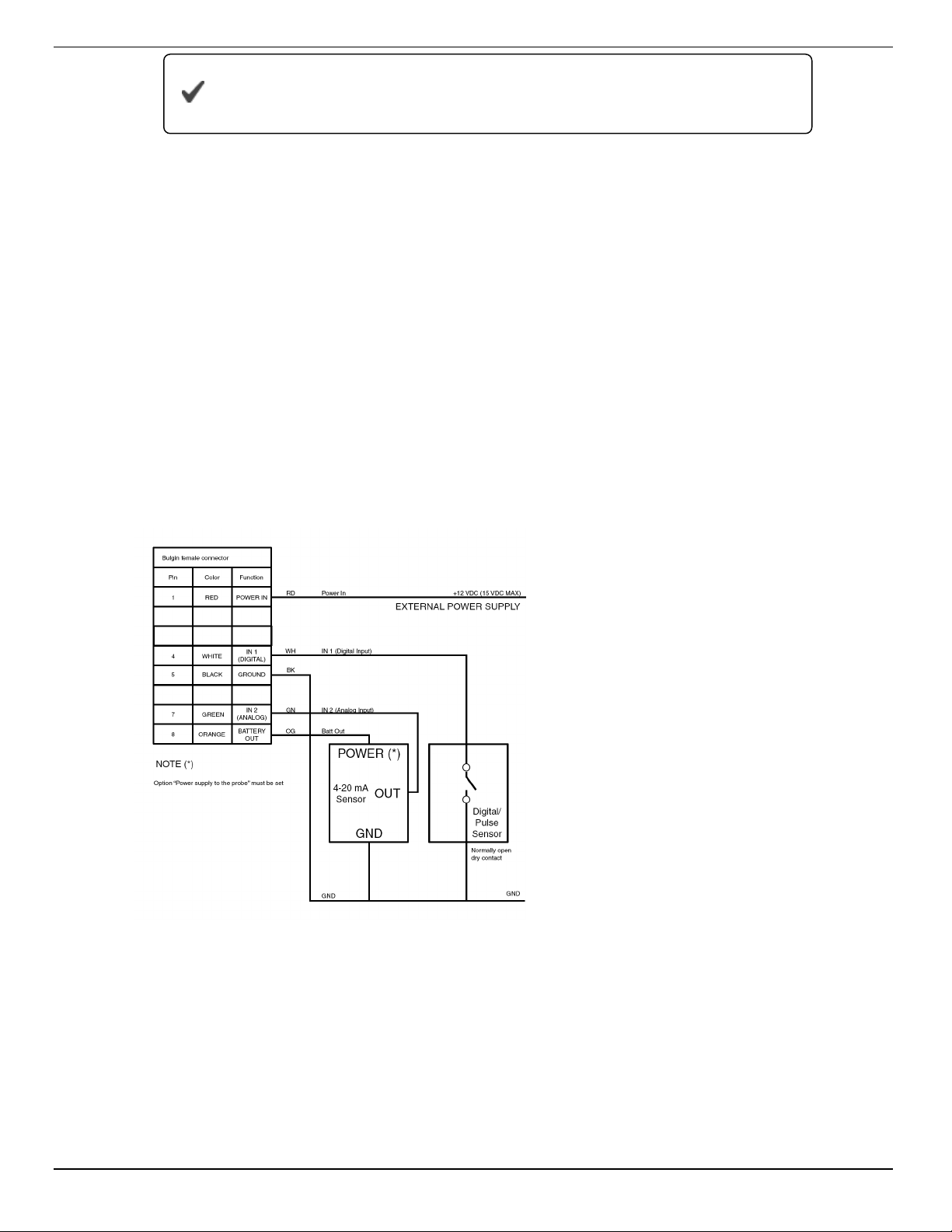
Digital, Pulse, and Analog Input
The Tube supports digital, pulse, or analog device input via a stripped-and-tinned cable
that connects to the Tube communication port. This device can be set up in the Tube
Tool.
Wiring Diagram
Connecting the Tube to the Computer
1. Connect the setup cable to the communication port of the Tube and to the computer.
2. Download the ANT Tube Tool software from
www.in-situ.com/support
3. Install and open the ANT Tube Tool software.

800-446-7488
17
www.in-situ.com
4. Select the correct serial port. A serial-to-serial adapter is typically COM1. A USB-to-
serial adapter is typically a different COM number.
Input Configuration
1. Click General information, parameters, and options.
2. Click the Options tab.
lFor a digital or pulse input: enter a Parameter name, value of a parameter,
and parameter units under Input 1.
lFor an analog input: enter a Parameter name, high and low values, and
parameter units under Input 2.
The Power supply to the probes checkbox must be checked for
analog input devices.
For HydroVu users, the Parameter name and units are directly
passed to the cloud. They cannot be changed from HydroVu.
3. Click Write options and parameters.
4. Close the window. Click Probe and set-point configuration.
5. From an open probe drop down menu, select Digital in, Pulse in, or Analog in.
6. Click Write Probe and set-points.
7. Close the window.
If you require alarming for the input device, continue with steps 8-12.
8. Click theParameters monitoring tab.
9. Select the input from one of the probe drop down menus.
10. Select the parameter from the parameter drop down menus.
11. Set the Warning and Alarm levels for the parameter, and set the level mode.
12. Click Write Probe and set-points.
Disconnect the communication cable and remember to connect
the stripped-and-tinned cable of the device to the Tube before
conducting any testing or when deploying the device.

800-446-7488
18
www.in-situ.com
Field Installation
Deploy the Tube
Deploy your In-Situ Instrument as described in the Owner's Manual.
If you are deploying the Tube inside a well casing using the In-Situ bail, follow the
instructions included with the bail.
If you are deploying the Tube inside a well casing using a different method, use a
suspension method rated for the weight of the entire system. The Tube weighs 1730 g
(3.81 lbs). You must account for the weight of your cable and instrument as well.
Improving Signal Quality
Cellular signal depends on several factors, including coverage area, antenna type, and
objects in the area that may cause interference.
If your Tube is receiving poor signal or frequently misses transmissions, you can check
the following to help determine the cause.
∙ The well casing may prevent the Tube from sending or receiving transmissions.
Consider using an external antenna (PN 0062240) that can be mounted on the top of
the well to prevent casing interference.
∙ Check the cellular provider's coverage area map. Your deployment area may be in a
non-coverage area.
∙ Check the area surrounding your equipment. Objects like trees, electrical wires, and
cement walls can affect cell reception. Consider moving the Tube to a different area to
test reception.
∙ If your system cannot be moved, consider using a different type of antenna that can be
mounted away from potential interference.
Troubleshooting
Troubleshooting Common Issues
I Can't Connect
1. Activate the modem and wait 5 seconds. See "Activate the Modem" on page 20.
2. Verify SIM installation. See "SIM Card" on page 21.
3. Verify your SIM has been activated through your service provider.
4. Verify network band type through your service provider (e.g., GSM versus GPRS).
5. Verify signal quality. See "Activate the Modem" on page 20.
800-446-7488
19
www.in-situ.com
6. Verify the current band and network. In-Situ recommends 850/900 MHz dual-band
and Automatic, 3G preferred for the Western Hemisphere, and 850/900/1800/1900
quad-band and Automatic, 3G preferred for the Eastern Hemisphere. See "Activate
the Modem" on page 1.
7. Conduct an FTP or email test. See "Restart Device and Test Communications" on
page 15.
8. Check probe readings:
1. Click Functional mode and test.
2. Click Probes, real-time reading.
3. Click theImmediate reading probes button. Note the units used for
level readings.
9. Verify your reading and transmission settings. See "Set Probe Reading Schedule"
on page 14.
10. Restart the device. See "Restart Device and Test Communications" on page 1.
Units that have been restored to factory settings must have their
batteries unplugged and plugged back in to communicate.
I Cannot Select Barometric Compensation on my Non-vented Tube
1. Open the ANT Tube Tool.
2. Enter the following characters into the PASSWORD field (case sensitive):
p1RLa
3. Click Functional mode and testing.
4. Click the Sending Commands tab.
5. Enter the following string into the command to be sent box:
@>E97,00,17,05<
6. Click Send Command.
Error Codes and Messages
Problem Possible Solutions
The software displays the message,
"The Tube didn't reply in the
expected time. Please verify if it is
connected."
∙ Check connections between the Tube and the computer.
∙ Check the COM selected in the serial port dropdown menu.
∙ Open the Tube and check that the battery is connected.
NOT_REG Verify the antenna is installed. Verify signal strength.

800-446-7488
20
www.in-situ.com
Problem Possible Solutions
Error 305 Check the phone number field for forbidden characters.
Error 515 Wait 15 minutes and resend the SMS.
Error 803 Verify the APN. Verify that the SIM has been enabled. Verify
signal strength.
Error 810 Insert a SIM card into the Tube.
Error 811 Enter the SIM PIN number.
Error 812 Verify the APN. Verify that the SIM has been enabled.
Error 813-817 Verify the username and password for the APN.
Error 831 Verify the directory exists & that you have permission to
access.
Error 832 Verify the Port number.
Error 833 Verify access to the Port.
Error 840 Someone is already logged in with your credentials.
Error 841 Verify the FTP server, username, and password.
Error 842 Check the FTP server functionality.
Error 861 Username is rejected by the server.
Error 862 Password is rejected by the server.
Error 865 Authentication error.
Error 866 Server is not ready.
Error 867 Email retrieving error.
Error 868 Email size error.
Error 880 Sender email address rejected by server.
Error 881 Recipient email address rejected by server.
Error 882-884 Email error.
Activate the Modem
Activate the modem if the Test FTP functionality returns an error.
1. Click Functional mode and test.
2. Click the Modem, settings, and tests tab.
3. Click the Activate modem button.
Other manuals for Tube 300R
1
This manual suits for next models
2
Table of contents
Other In-situ Data Logger manuals

In-situ
In-situ HERMIT SE2000 User manual

In-situ
In-situ Tube 300R User manual

In-situ
In-situ Aqua TROLL 700 User manual

In-situ
In-situ Rugged TROLL 200 User manual

In-situ
In-situ Tube 300S User manual

In-situ
In-situ Rugged TROLL 100 User manual

In-situ
In-situ Aqua TROLL 600 User manual

In-situ
In-situ VuLink CI User manual

In-situ
In-situ Tube 300S User manual


