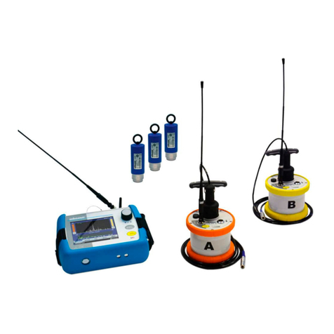
sebaKMT HL 7000 User manual

Consultation with SebaKMT
1
User Manual
Acoustic leak detection system
HL 7000
Issue: 01 (06/2018) - EN
Article number: 86357
Mess- und Ortungstechnik
Measuring and Locating Technologies
Elektrizitätsnetze
Power Networks
Kommunikationsnetze
Communication Networks
Rohrleitungsnetze
Water Networks
Abwassernetze
Sewer Systems
Leitungsortung
Line Locating

Consultation with SebaKMT
2

Consultation with SebaKMT
3
Consultation with SebaKMT
The present system manual has been designed as an operating guide and for
reference. It is meant to answer your questions and solve your problems in as fast and
easy a way as possible. Please start with referring to this manual should any trouble
occur.
In doing so, make use of the table of contents and read the relevant paragraph with
great attention. Furthermore, check all terminals and connections of the instruments
involved.
Should any question remain unanswered or should you need the help of an authorized
service station, please contact:
Seba Dynatronic
Mess- und Ortungstechnik GmbH
Hagenuk KMT
Kabelmesstechnik GmbH
Dr.-Herbert-Iann-Str. 6
D - 96148 Baunach
Phone: +49 / 9544 / 68 –0
Fax: +49 / 9544 / 22 73
Röderaue 41
D - 01471 Radeburg / Dresden
Phone: +49 / 35208 / 84 –0
Fax: +49 / 35208 / 84 249
E-Mail: sales@sebakmt.com
http://www.sebakmt.com
SebaKMT
All rights reserved. No part of this handbook may be copied by photographic or other means unless SebaKMT
have before-hand declared their consent in writing. The content of this handbook is subject to change without
notice. SebaKMT cannot be made liable for technical or printing errors or shortcomings of this handbook.
SebaKMT also disclaims all responsibility for damage resulting directly or indirectly from the delivery, supply,
or use of this matter.

Terms of Warranty
4
Terms of Warranty
SebaKMT accept responsibility for a claim under warranty brought forward by a
customer for a product sold by SebaKMT under the terms stated below.
SebaKMT warrant that at the time of delivery SebaKMT products are free from
manufacturing or material defects which might considerably reduce their value or
usability. This warranty does not apply to faults in the software supplied. During the
period of warranty, SebaKMT agree to repair faulty parts or replace them with new parts
or parts as new (with the same usability and life as new parts) according to their choice.
This warranty does not cover wear parts, lamps, fuses, batteries and accumulators.
SebaKMT reject all further claims under warranty, in particular those from consequential
damage. Each component and product replaced in accordance with this warranty
becomes the property of SebaKMT.
All warranty claims versus SebaKMT are hereby limited to a period of 12 months from
the date of delivery. Each component supplied by SebaKMT within the context of
warranty will also be covered by this warranty for the remaining period of time but for 90
days at least.
Each measure to remedy a claim under warranty shall exclusively be carried out by
SebaKMT or an authorized service station.
This warranty does not apply to any fault or damage caused by exposing a product to
conditions not in accordance with this specification, by storing, transporting, or using it
improperly, or having it serviced or installed by a workshop not authorized by SebaKMT.
All responsibility is disclaimed for damage due to wear, will of God, or connection to
foreign components.
For damage resulting from a violation of their duty to repair or re-supply items,
SebaKMT can be made liable only in case of severe negligence or intention. Any liability
for slight negligence is disclaimed.
Since some states do not allow the exclusion or limitation of an implied warranty or of
consequential damage, the limitations of liability described above perhaps may not
apply to you.

Terms of Warranty
5
Contents
Consultation with SebaKMT...........................................................................................3
Terms of Warranty...........................................................................................................4
1Safety Instructions...........................................................................................9
1.1 General Safety Instructions and Warnings.........................................................9
1.2 General Notes ....................................................................................................9
2Technical data & scope of delivery ..............................................................11
2.1 Technical data..................................................................................................11
2.2 Included in delivery...........................................................................................13
3Technical description ....................................................................................14
3.1 HL 7000 system ...............................................................................................14
3.2 HLE 7000 operating unit...................................................................................15
3.2.1 Function and structure......................................................................................15
3.2.2 Operation..........................................................................................................16
3.2.3 Power supply....................................................................................................16
3.2.4 GPS..................................................................................................................18
3.2.5 Automatic switch off .........................................................................................18
3.2.6 Force shutdown (RESET) ................................................................................18
3.3 CS-7 carrying pole............................................................................................19
3.3.1 Function and structure......................................................................................19
3.3.2 Communication ................................................................................................20
3.3.3 Power supply....................................................................................................21
3.3.4 Automatic switch off .........................................................................................22
3.3.5 Force shutdown (RESET) ................................................................................22
3.4 Headphones.....................................................................................................22
3.4.1 Introduction.......................................................................................................22
3.4.2 Switching on/off................................................................................................22
3.4.3 Pairing ..............................................................................................................22
3.4.4 Volume .............................................................................................................23
3.4.5 Power supply....................................................................................................23
3.5 Transport case .................................................................................................25
3.5.1 Safety instructions............................................................................................25
3.5.2 Design ..............................................................................................................25
3.5.3 Power connection.............................................................................................26
3.6 Carrying and attachment options .....................................................................27
4Start-up............................................................................................................29
4.1 Connecting a sensor ........................................................................................29
4.1.1 Mounting a microphone or gas sensor on the CS-7 carrying pole...................29
4.1.2 Connecting a wired microphone to the HLE 7000 ...........................................30
4.2 Switching on.....................................................................................................31
4.3 Checking the basic settings .............................................................................32

Terms of Warranty
6
4.3.1 Mute button ......................................................................................................32
4.3.2 System time......................................................................................................32
4.3.3 Hearing protection............................................................................................33
4.4 Switching off.....................................................................................................33
5Performing measurements............................................................................34
5.1 Level measurement..........................................................................................34
5.1.1 Introduction.......................................................................................................34
5.1.2 Procedure.........................................................................................................34
5.1.3 Display..............................................................................................................35
5.1.4 Tools.................................................................................................................36
5.1.5 Customising the display ...................................................................................38
5.2 Long-term measurement..................................................................................39
5.2.1 Procedure.........................................................................................................39
5.2.2 Display..............................................................................................................40
5.2.3 Tools.................................................................................................................41
5.2.4 Customising the display ...................................................................................43
5.3 Pinpoint location...............................................................................................44
5.3.1 Introduction.......................................................................................................44
5.3.2 Procedure.........................................................................................................44
5.3.3 Display..............................................................................................................47
5.3.4 Tools.................................................................................................................48
5.3.5 Customising the display ...................................................................................50
5.4 Pipe locating.....................................................................................................51
5.4.1 Introduction.......................................................................................................51
5.4.2 Procedure.........................................................................................................51
5.4.3 Display..............................................................................................................54
5.4.4 Tools.................................................................................................................55
5.4.5 Customising the display ...................................................................................57
5.5 Tracer gas detection (H2 sensor).....................................................................58
5.5.1 Introduction.......................................................................................................58
5.5.2 Procedure.........................................................................................................58
5.5.3 Display..............................................................................................................60
5.5.4 Tools.................................................................................................................60
5.5.5 Customising the display ...................................................................................61
6System settings..............................................................................................62
6.1 Introduction.......................................................................................................62
6.2 Overview of the adjustable parameters............................................................62
7HydroluxView software..................................................................................67
8Data transfer ...................................................................................................69
9Saved measurements ....................................................................................70
9.1 Open menu.......................................................................................................70
9.2 Show measurement .........................................................................................70

Terms of Warranty
7
9.3 Change name...................................................................................................71
9.4 Delete measurement........................................................................................71
10 Updating the firmware ...................................................................................72

Terms of Warranty
8

Safety Instructions
9
1 Safety Instructions
1.1 General Safety Instructions and Warnings
Do not drop the device / the system’s components or subject it / them to
strong impacts or mechanical shocks.
The limits described under Technical Data may not be exceeded.
The device / system must be in a technically perfect condition for
measurement.
The indicated degree of protection can only be ensured if plugs or the
provided protection caps are put in all sockets of the device.
The plugs of the supplied connection cables are only compliant to the
indicated degree of protection as long as they are plugged in. Plugs
which are not connected or which are connected in a wrong way are not
protected from water and dust ingress.
The transport cases of the system have electrical components.
Therefore, the cases must be protected from water and moisture.
1.2 General Notes
This manual contains basic instructions for the commissioning and operation of the
device / system. For this reason, it is important to ensure that the manual is always
available to the authorised and trained operator. He needs to read the manual
thoroughly. The manufacturer is not liable for damage to material or humans due to non-
observance of the instructions and safety advices provided by this manual.
Locally applying regulations have to be observed!
The following signal words and symbols are used in this manual and on the product
itself:
Signal word /
symbol
Description
CAUTION
Indicates a potential hazard which may result in moderate or minor
injury if not avoided.
NOTICE
Indicates a potential hazard which may result in material damage if
not avoided.
Serves to highlight warnings and safety instructions.
As a warning label on the product it is used to draw attention to
potential hazards which have to be avoided by reading the manual.
Serves to highlight important information and useful tips on the
operation of the device/system. Failure to observe may lead to
unusable measurement results.
Serves to highlight important information which are meant to protect
the device/system of water or moisture.
Safety precautions
Labelling of safety
instructions

Safety Instructions
10
Check the contents of the package for completeness and visible damage right after
receipt. In the case of visible damage, the device must under no circumstances be taken
into operation. If something is missing or damaged, please contact your local sales
representative.
It is important to observe the generally applicable regulations of the country in which the
device will be operated, as well as the current national accident prevention regulations
and internal company directives (work, operating and safety regulations).
Use genuine accessories to ensure system safety and reliable operation. The use of
other parts is not permitted and invalidates the warranty.
Repair and maintenance work has to be carried out by SebaKMT or authorised service
partners using original spare parts only. SebaKMT recommends having the system
tested and maintained at a SebaKMT service centre once a year.
SebaKMT also offers its customers on-site service. Please contact your service centre if
needed.
This device is designed for industrial use. When used at home it could cause
interference to other equipment, such as the radio or television.
The interference level from the line complies with the limit curve B (living area), the
radiation level complies with the limit curve A (industrial area) according to EN 55011.
Given that living areas are sufficiently far away from the planned area of operation
(industrial area), equipment in living areas will not be impaired.
The lithium batteries of the device are dangerous goods. The transport of the batteries
itselves and of devices which contain such batteries is subject to regulations based on
the UN Model Regulations “Transport of Dangerous Goods” (ST/SG/AC.10-1).
Please inform yourself about the transportation requirements and follow them when
shipping the device.
Check contents
Working with products
from SebaKMT
Repair and
maintenance
Electromagnetic
radiation
Special transportation
requirements

Technical data & scope of delivery
11
2 Technical data & scope of delivery
2.1 Technical data
These parameters apply to the entire system:
Frequency analysis
0 - 4000 Hz
Audio sample rate
16 kHz
Operating time
> 10 hours
Operating temperature
-20 °C to +60 °C
Storage temperature
-25 °C to +70 °C
Communication
Bluetooth ®
USB cable
Microphone cable
These parameters apply to the HLE 7000 control unit:
Screen
4.3'' colour display with touch function
Input
Touch display
On/off button
Favourites button
3 navigation buttons
Mute button
LEDs
On/off
Charge control
Storage
min. 100 measurements including audio recordings
(wav files)
Power supply
internal lithium-ion battery, (3.6 V / 10 Ah)
Operating time
> 10 hours
Charge
5 V / 1.5 A
Charging time
Approx. 8 hours
Dimensions
200 x 95 x 45 mm
Weight
0.6 kg
Protection class
IP 65
GPS
internal receiver and antenna
Wireless
2 internal Bluetooth modules
These parameters apply to the CS-7 carrying pole:
LEDs
On/off
Mute active
Radio active
Battery status (3 LEDs)
Ground light
Buttons
On/off
Muting
Ground light
Interfaces
Bluetooth
universal sensor connection
Charging socket
HL 7000 system
HLE 7000
CS-7 carrying pole

Technical data & scope of delivery
12
Power supply
internal lithium-ion battery, (3.6 V / 3.35 Ah)
Charge
5 V / 0.45 A
Charging time
Approx. 8 hours
Dimensions
220 x 80 x 650 mm
Weight (without sensor)
0.7 kg
Protection class
IP 65
Wireless
internal Bluetooth module
These parameters apply to the ground microphone:
Sensor
active piezo microphone
Dimensions
Ø 230 mm x 175 mm
Weight
2.7 kg
Protection class
IP 67
Adapter
Measuring tip, three-point foot adapter
These parameters apply to the sensor rod microphone:
Sensor
active piezo microphone
Dimensions
Ø 54 mm x 143 mm
Weight
0.8 kg
Protection class
IP 67
Adapter
Sensor rod
These parameters apply to the universal microphone:
Sensor
active piezo microphone
Dimensions
Ø 49 mm x 103 mm
Weight
0.4 kg
Protection class
IP 68
Connection
Cables
Adapter
Magnetic adapter
These parameters apply to the H2sensor:
Sensor
H2sensor
Dimensions
Ø 85 mm x 190 mm
Weight
0.32 kg
Protection class
IP 54
Ground microphone
PAM W-7
Sensor rod microphone
PAM T-7
Universal microphone
PAM Corr-2
Tracer gas sensor
PAM H-7

Technical data & scope of delivery
13
2.2 Included in delivery
The HL 7000 basic set includes the following parts:
Part
Description
Serial no.
HLE 7000
Hydrolux receiving and operating unit
1009672
Bluetooth headphones
90019021
CS-7
Carrying pole with operating buttons
1009674
PAM W-7
Wind-protected ground microphone
1009673
Mains supply unit
SM-SNG FW8000USB
Power adapter 5V/2.2A
90025102
VK 130
Connection and charging cable
90022223
TP W-7
Three-point foot adapter
2010837
HL-7000-K
Complete case for HL 7000
2010797
USB stick, HydroluxView
HL 7000 PC-SW
USB data storage with PC software
HydroluxView-3
1011008
Bracket, HL 7000
Holder for HLE 7000
90025467
Mounting set bracket,
HL 7000
2011128
Mounting set belt clip,
HL 7000
2011129
Manual
Operating manual
The following accessories are optionally available:
Part
Description
Serial no.
PAM T-7
Sensor rod microphone
1010396
Foot traverse, PAM T-3
Foot piece for PAM T-3 / T-7
820018811
PAM H-7
Tracer gas sensor
1010671
PAM CORR-2
Active universal microphone for direct
connection to the HLE 7000 control panel
820019615
Basic set
Optional

Technical description
14
3 Technical description
3.1 HL 7000 system
The Hydrolux HL 7000 is used for acoustic leak location on pipelines. It consists of an
operating unit, a universal carrying pole, various microphones and Bluetooth®
headphones.
By connecting different sensors to the carrying pole, the acoustic recording of ground
noise, direct listening to the pipe and leak detection with the help of tracer gas are
possible.
The transmission of the detected leak noise or the recorded measured values takes
place wirelessly via a Bluetooth connection.
Function and structure
Communication
®
®

Technical description
15
3.2 HLE 7000 operating unit
3.2.1 Function and structure
The HLE 7000 device is the operating unit of the HL 7000 system. It is the
communication hub between the CS-7 sensor carrying pole and the headphones. On
the screen, the recorded measured values are displayed. At the same time, the touch-
sensitive screen is used to enter all commands and operating steps.
On the HLE 7000 you will find the following operating elements, lights and connection
sockets:
Element
Description
On/Off/Home button & LED
Short press
…
Switches on the device or opens the home screen
Long press
…
Switches the device off
LED lights up green
…
The device is switched on
LED turns red
…
Battery is being charged
LED flashes red
…
Error during charging
Mute button
Button for starting/stopping the measurement
Microphone jack
For connecting the PAM CORR-2 microphone (optional)
USB port
For connecting the charging cable in the case
For connecting the connection cable for data transfer
Touch display
Touch-sensitive screen for display of measured data and operation of the device
3 buttons for the screen navigation
Quick selection button
Short press
…
Opens a certain menu or performs a specific action
Long press
…
Defines the opened measurement type as a quick selection
option
Design

Technical description
16
3.2.2 Operation
The screen of the HLE 7000 is touch sensitive.
The device is operated by tapping the displayed buttons on the screen.
If you hold down a button for a long time, a field appears next to the area with a brief
explanation of the function of this button (referred to as a tooltip).
Next to the screen you will find three buttons, which can also be used to operate the
device.
Use the two cursor keys to move from button to button in the screen.
Press the OK button to open the selected button.
When the quick-selection button is briefly pressed, the screen goes directly to a
specific menu or a specific action is performed. Which menu or action this is can be set
in the system settings of the HLE 7000 (see page 62).
If the quick-selection button is pressed and held (for about 3 seconds) while a
measurement type is currently open on the screen, then this mode is set as the new
quick-selection function.
Example: If you go to the Pinpointing menu and then press the quick-selection button for
3 seconds, the pinpointing measurement is set as favourite. From now on, when you
press the quick-selection button, Pinpointing menu will open directly.
3.2.3 Power supply
The device is equipped with an internal lithium-ion battery. At full charge, the average
operating time is approximately 10 hours, depending on actual usage.
The current battery level is displayed at the bottom left of the screen.
As soon as the battery of the device has reached a minimum, a message appears on
the screen. The device should then be charged as soon as possible.
Touch display
Tooltip
Navigation buttons
Quick selection button
Battery status
Keep button
pressed!
Deleting the last level

Technical description
17
The device can be charged in the transport case, provided the case is connected to a
mains supply.
Take one of the charging cables in the case with a round plug and connect it to the USB
port of the HLE 7000. Note the marking. You must feel the plug engage.
The device can also be connected to the mains for charging. Use the supplied power
adapter and the VK 130 connection cable.
Connect the round plug of the cable to the USB socket of the HLE 7000. Plug the
other end of the cable into the power adapter and the power adapter into an electrical
outlet.
When charging in the case or when using the included power adapter, the charging time
is about 8 hours. If a third-party power supply unit with less than 1.5 A charge current is
used, the charging time increases considerably.
During charging, the I/O LED on the device will turn solid red. The red light goes out as
soon as the battery is fully charged.
The LED flashes red when an error occurs during charging. The charging process is
aborted in this case.
While the HLE 7000 is connected to a computer, charge current flows from the
computer to the device via the USB connection. The I/O LED on the device turns red.
However, the charge current is too low to charge the battery noticeably.
Charging in the
transport case
Charging on the mains
Duration
LED
USB

Technical description
18
3.2.4 GPS
The HLE 7000 operating unit has a standard integrated GPS module. The GPS module
will start a signal search immediately after the HLE 7000 is switched on.
A GPS icon is shown in the info bar at the bottom of the screen.
The colour of the icon indicates whether GPS is available.
Red
…
No GPS reception
Green
…
GPS reception is good, position determination is possible
As soon as a measurement is made, the position, time and date of the measurement
are determined and stored in the device, together with the measurement result.
3.2.5 Automatic switch off
The HLE 7000 operating unit switches itself off if no Bluetooth contact has taken place
for a certain period of time and no input has been made. The length of this time span
can be specified in the system settings (see page 62).
3.2.6 Force shutdown (RESET)
If necessary, you can force the device to switch off.
Simultaneously press the I/O button and the OK button until the green LED turns off.

Technical description
19
3.3 CS-7 carrying pole
3.3.1 Function and structure
“CS-7” is the sensor carrying pole of the HL 7000 system.
At the lower end of the carrying pole, the various microphones or the gas sensor of the
set can be mounted.
In the handle of the carrying pole there is an electronics unit and a Bluetooth module for
the transmission of recorded data to the HLE 7000 operating unit.
The internal battery supplies the device itself and the installed microphone with power.
On the handle you will find a charging socket and the following buttons and LEDs:
Element
Description
I/O button & LED
Button for switching device on/off.
The LED lights up as long as the device is switched on.
Mute button & LED
Button for starting/stopping the measurement.
The LED lights up as long as a measurement is running.
LED goes on
…
Measurement in progress;
Headphones reproduce the recorded noise;
Screen displays current measured values
LED does not go on
…
Measurement is interrupted;
Headphones are muted;
Screen is frozen
Battery status display
Three LEDs are lit
…
Battery fully charged
Two LEDs are lit
…
Battery level good
One LED is lit
…
Low battery
Flashing
…
The rechargeable battery is being charged
Light button
To turn on the floor light
Wireless LED (blue)
Indicates that there is an active Bluetooth connection
Floor LED (white)
A white LED lights down at the push of the light button
Connection socket for charging cable

Technical description
20
3.3.2 Communication
Communication between the CS-7 carrying pole and the HLE 7000 operating unit takes
place via Bluetooth.
The carrying pole is already paired with the operating unit at the factory, which means
that the Bluetooth connection is always established automatically when the two devices
are switched on.
If a situation occurs in which the pairing needs to be performed again (for example, after
the HLE 7000 has been reset to factory defaults), proceed as follows:
Step
Description
1
In the Start menu of the HLE 7000, tap
Management >> Settings >> Paired microphone.
2
Simultaneously press the On/Off button on the CS-7 carrying pole and the
mute button until the red and blue LEDs flash alternating.
3
On the HLE 7000 screen, tap the button .
Result: The search for Bluetooth devices in the area begins. A bar indicates
the progress. After a successful search, the name of the found Bluetooth
device is displayed. If no device or the wrong device has been found, repeat
the search.
4
Tap on the button.
Result: The CS-7 carrying pole and the HLE 7000 are paired.
When finished, the screen returns to the Settings menu.
The CS-7 carrying pole is now automatically detected by the HLE 7000 when
switched on.
Pairing
Table of contents
Other sebaKMT Security Sensor manuals
Popular Security Sensor manuals by other brands
Danfoss
Danfoss DGS-SC Installation and operation
SHENZHEN FLYING INDUSTRY DEVELOPMENT
SHENZHEN FLYING INDUSTRY DEVELOPMENT W-01 quick start guide
Detectors Incorporated
Detectors Incorporated D171SS 1IR + UV instruction manual
Mazda
Mazda MAZ-95-130-KT Operation manual
LEGRAND
LEGRAND 088230 manual
LEGRAND
LEGRAND 3445 quick start guide
