manuals.online logo
Brands
  1. Home
  2. •
  3. Brands
  4. •
  5. HELVAR
  6. •
  7. Security Sensor
  8. •
  9. HELVAR digidim 314 User manual

HELVAR digidim 314 User manual

1
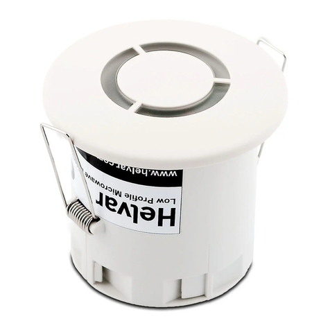
Helvar 314 Tilting Microwave Detector Installation Guide
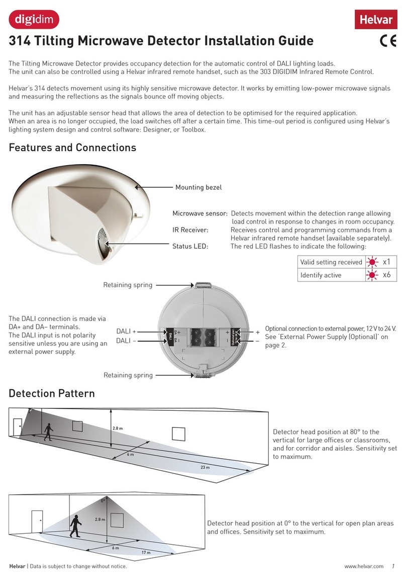
Features and Connections
Microwave sensor
Detects movement within the detection range allowing load
control in response to changes in room occupancy.
IR receiver
Receives control and programming commands from a
303 IR (infrared) handset (available separately).
Status LED
The red LED flashes to indicate the following:
DALI connection
The DALI connection is made via DA+ and DA– terminals.
The DALI input is not polarity sensitive (unless you are using an
external power supply).
External power connection (optional)
– Microwave sensor
– IR receiver
– Status LEDs
Mounting bezel
Retaining spring
Retaining spring
DALI +
DALI -
+
-
The 314 Tilting Microwave Detector provides occupancy detection for the automatic control of DALI lighting loads.
The unit can also be controlled using the Helvar 303 IR (infrared) remote control handset.
The 314 detects movement using its highly sensitive microwave detector. It works by emitting low-power microwave signals
and measuring the reflections as the signals bounce off moving objects.
The 314 has an adjustable sensor head that allows the area of detection to be optimised for each particular purpose.
When an area is no longer occupied, the load will switch off after a certain time. This time-out period is configured using
Helvar’s lighting system design and control software: Designer, or Toolbox.
Valid setting received
Identify active
R
R R R R R R
R
= Red LED
Helvar 314 Tilting Microwave Detector
Installation Guide
1. Install the unit: see ‘Connection and Fixing’ on page 2.
2a. Connect the DALI terminal blocks to the sockets at the rear of the sensor.
2b. If required, connect the optional power supply: see ‘External Power Supply (Optional)’ on page 3.
3. Power the unit up.
4. After the lighting load switches on, by default it will switch off after 20 minutes of no movement detected.
Installation
2Helvar 314 Tilting Microwave Detector: Installation Guide
Head Locking
Connection and Fixing
Mounting hole Surface back box SBB-B
1. 2.
Remove metal
locking clip from
rear of unit
• Adjust head to required
position
• Push clip into position
shown below to lock
head
• To remove clip, lever out
with a small screwdriver
Attach
cable
clamp
External
power cable
optional
Ø 78 mm
WARNING
Take special
care when
bending springs
to install the unit
93
82
85
60
50
Ø5
WARNING
Take special care
when bending
springs to install
the unit
Fixing screw
• Position the sensor so that the occupants of the room are normally inside the detection zone.
• Do not install the sensor within 1 m of any lighting, forced air heating, or ventilation equipment.
• Do not fix the sensor to an unstable or vibrating surface.
• Install the unit as far away as possible from the surface of metal objects.
• The detection pattern illustrated (see ‘Detection Pattern’ on page 3) is based on a mounting height of 2.8 m.
• A lower mounting height will decrease the overall size of the detection zone.
Installation Notes
1. 2.
3. 4.
3
Helvar 314 Tilting Microwave Detector Installation Guide
Ideal for open plan areas and offices
You can use the Helvar 303 IR Remote Control to send
signals to the 313 detector to:
– recall lighting scenes 1–4;
– adjust light levels;
– store current level; and
– install preset levels for scenes 1–4.
Remote Control
Other Functions
Ideal for large office or classroom, and for corridors and aisles
Sensitivity
Adjust the sensitivity using Designer, or Toolbox (Helvar’s lighting system design and control software).
Note: On maximum sensitivity, the detector unit is extremely sensitive to movement and may detect through glass, thin walls or
partitions. If this causes a problem, reduce its sensitivity.
Adjusting On, Exit and Transition time-Outs
The default time-outs for On, Exit and Transition can be altered using Designer, or Toolbox.
Check connection to DALI Network
To check the sensor is correctly connected the DALI network, use the Identify function in Designer, or Toolbox.
Using Designer and Toolbox Software
When using Designer, connect the PC to the lighting network via a Helvar Router.
When using Toolbox, connect the PC to the lighting network via a Helvar serial or USB interface.
For further information about Designer and Toolbox, see the System Software section of www.helvar.com.
Helvar 303 IR Remote Control
See the 303 Remote User Manual
(Helvar Document D004744) for
full details.
Sensitivity set to maximum.
Detector head position: 80°
Sensitivity set
to maximum.
Detector head
position: 0°
Area of
lower
sensitivity
Area
oflower
sensitivity
Area of
higher
sensitivity
Area
ofhigher
sensitivity
2.8 m
22 m 6m
Detection Pattern
External Power Supply (Optional)
Current-limited external power supply unit
If an external power supply is required, use a Helvar 401, 402 or 403 power supply unit.
Contact your Helvar representative if you need any further information.
DALI Helvar DALI PSU
+
+
-
-
Helvar 401
Helvar 402
Helvar 403
AC
DA+ DA
-
SC
iDim Sense
comcom
++
--
++
--
www.helvar.com
www.helvar.com
iDim Solo
Interface Module
iDim Solo
Interface Module
comcom 64 mA
DALI 1
64 mA
DALI 1
SW 1SW 1
SW 2SW 2
32 mA
DALI 2
32 mA
DALI 2
L
N
L
N
tc
40 mA
100 - 240 V50 - 60 Hz
tc: 75°C
ta: 10°C...50°C
9 mm
0,5...1,5
16
4
www.helvar.com
Helvar 314 Tilting Microwave Detector: Installation Guide Data subject to change without notice
Doc. 7860269, issue 03, 2015-02-05
Hole diameter: Ø78 mm Protective cover
Technical Data
Dimensions
3.5 mm
3.5 mm
92 mm
85 mm
78 mm
70 mm
Connections
External power /
DALI:
Removable terminal block
Wire size: 0.5 mm² –1.5mm²
Solid or stranded
Cable rating: All cables must be mains
rated
Power
DALI supply input: 13 V to 22.5 V
DALI consumption: 40 mA
Note: DALI consumption is
less than 2 mA when external
power is supplied to the unit.
If an external power supply is
used, it should be a Helvar 401,
402 or 403 power supply unit.
(Optional) External
Power:
12 V to 24 V; 0.5 W
Remote control functions
Use Helvar 303
remote control to:
– recall lighting scenes 1–4;
– adjust light levels;
– store current level; and
– install preset levels for
scenes 1–4.
Note: Adjust sensitivity using
Designer, or Toolbox (and not
by remote control unit).
Microwave operating frequency
Model Frequency
314 10.687 GHz
UK, China, Hong Kong,
India, Malaysia, Middle East,
Singapore
314/R2 10.525 GHz
Australia, and Europe, except
for: UK, France, Portugal,
Germany, Switzerland,
Austria, Slovak Republic,
Republic of Ireland
314/R3 9.900 GHz
France, Portugal, Switzerland
314/R4 9.350 GHz
Austria, Germany, Slovak
Republic
314/R5 10.41 GHz
Republic of Ireland
Mechanical data
Mounting hole
diameter:
78 mm
Bezel diameter: 85 mm
Recommended
clearancedepth (incl.
50 mm for cabling):
80 mm (without protective
cover);
100 mm (with protective
cover)
Material (casing): Flame retardant ABS andPC/
ABS
Finish / Colour: Matt / White
Weight: 124 g
IP code: IP30
Operating conditions
Ambient
temperature:
+10 °C to +35 °C
Relative humidity: Max. 90 %, noncondensing
Storage temperature: –10 °C to +70 °C
Conformity and standards
EMC immunity: EN 61000–6–1
EMC emission: EN 61000–6–3
Safety: EN 60730–1
Environment: Complies with WEEE
andRoHS directives
Version information
Software version: 6
Hardware version: Rev. 2
Other HELVAR Security Sensor manuals

HELVAR Digidim 311 User manual

HELVAR

HELVAR Digidim 311 User manual

HELVAR digidim 319 User manual

HELVAR

HELVAR digidim 319 User manual

HELVAR digidim 313 User manual

HELVAR

HELVAR digidim 313 User manual

HELVAR 314 Tilting User manual

HELVAR

HELVAR 314 Tilting User manual

HELVAR digidim 317 User manual

HELVAR

HELVAR digidim 317 User manual

HELVAR Digidim 317 User manual

HELVAR

HELVAR Digidim 317 User manual

HELVAR Digidim 313 User manual

HELVAR

HELVAR Digidim 313 User manual

HELVAR 318 User manual

HELVAR

HELVAR 318 User manual

HELVAR OB-1501 User manual

HELVAR

HELVAR OB-1501 User manual

HELVAR 311 User manual

HELVAR

HELVAR 311 User manual

Popular Security Sensor manuals by other brands

SSS Siedle SBMM 611-0 Product information

SSS Siedle

SSS Siedle SBMM 611-0 Product information

Robus R100LEDCCT3E-01 instruction manual

Robus

Robus R100LEDCCT3E-01 instruction manual

Atim Cloud Wireless ACW/LW8-CTS user guide

Atim Cloud Wireless

Atim Cloud Wireless ACW/LW8-CTS user guide

Fieldpiece DR82 user manual

Fieldpiece

Fieldpiece DR82 user manual

Balluff BTL7-C/E509-M Series user guide

Balluff

Balluff BTL7-C/E509-M Series user guide

Mier products Drive-Alert DA-606LK quick start guide

Mier products

Mier products Drive-Alert DA-606LK quick start guide

Visonic SD-304C PG2 installation instructions

Visonic

Visonic SD-304C PG2 installation instructions

SICK GSE6V operating instructions

SICK

SICK GSE6V operating instructions

Atsumi Electric IR36EXA installation manual

Atsumi Electric

Atsumi Electric IR36EXA installation manual

BW Technologies NH3 RESPONDER Quick reference guide

BW Technologies

BW Technologies NH3 RESPONDER Quick reference guide

TPI 720B User m manual

TPI

TPI 720B User m manual

NetVu FireVu Standalone installation manual

NetVu

NetVu FireVu Standalone installation manual

CTI CS-100 Calibration guide

CTI

CTI CS-100 Calibration guide

AGFA DR 10s user manual

AGFA

AGFA DR 10s user manual

Siemens RAR Series quick start guide

Siemens

Siemens RAR Series quick start guide

nologo FIRE-FE quick start guide

nologo

nologo FIRE-FE quick start guide

Siemens DF-30 Installation, Application, And Technical Instructions

Siemens

Siemens DF-30 Installation, Application, And Technical Instructions

resideo Honeywell Home PROOUTMV Installation and setup guide

resideo

resideo Honeywell Home PROOUTMV Installation and setup guide

manuals.online logo
manuals.online logoBrands
  • About & Mission
  • Contact us
  • Privacy Policy
  • Terms and Conditions

Copyright 2025 Manuals.Online. All Rights Reserved.