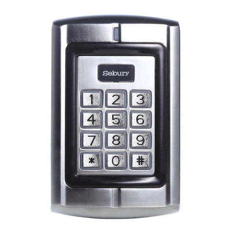
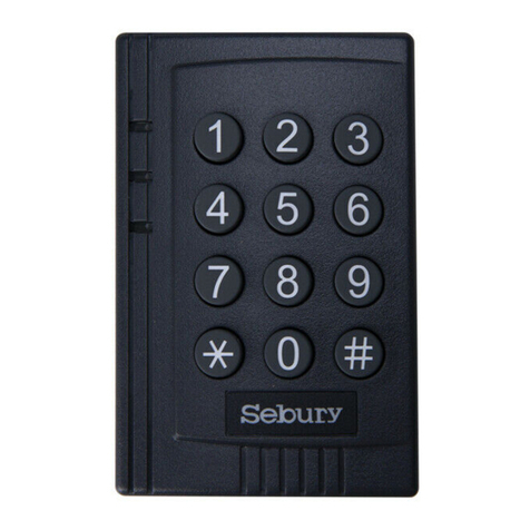
Sebury W1-B User manual

User manual
.9. . 10.
1
2
3
4
5
6
7
8
9
0
#
For a P IN use r
To un lock t he doo r
10.2 Doo r Rel ay, Doo r Open Dete ction, Alarm, F acility c ode S etti ngs
Doo r relay t ime set ting
To disa ble doo r open de tecti on.
(Fa ctory d efaul t setti ng)
6 0 #
To enab le door o pen det ectio n
6 2 #
Key pad Loc kout
Ala rm Outp ut
To rem ove th e alar m
To reset the Door Forced Open warning
Nor mal sta tus: No k eypad l ockou t
or al arm
7 0 # (Fa ctory d efaul t setti ng)
7 1 #
7 2 #
Rea d valid c ard or Ma ster Co de #
To ad d and de lete u sers i n card a nd PIN m ode ( 3 1 # )
.7. . 8.
To exit f rom the p rogra mming m ode
To chan ge the ma ster co de
To add a PI N user
* Mas ter cod e #
888 888 is th e defau lt fact ory mas ter cod e
To ente r the pro gramm ing mod e
*
Not e that to un dert ake the f ollowi ng pro grammi ng the ma ster us er mus t be logg ed in
The m aster c ode is an y 6 digit s
The I D numbe r is any nu mber be tween 1 ~ 2 500.
The P IN is any f our dig its bet ween 00 00 ~ 9999
wit h the exc eptio n of 1234 w hich is r eserv ed.
Use rs can be adde d contin uousl y withou t exitin g
pro gramm ing mod e
W1/W3-B Quick Reference Programming Guide
To add a ca rd use r Car ds can be a dded co ntinu ously w ithou t
exi ting fr om prog rammi ng mode
To dele te a PIN or a c ard us er
Use rs can be d elete d conti nuous ly with out
exi ting fr om prog rammi ng mode
1 Rea d Card #
Pre sent th e card
To Un lock t he doo r
Waterproof
Keypad/Reader/Controller
To Add a card and Pi n user
(Th e PIN is an y four di gits be tween
000 0 ~ 9 999 with the exce ptio n of
123 4 which i s reser ved.)
To chan ge a P IN in card and PIN
mod e (M etho d 1 ) No te t hat this is
don e outs ide pr ogra mmin g mode
so the us er ca n u nder take th is
the msel ves
To chan ge a P IN in card and PIN
mod e (M etho d 2 ) No te t hat this is
don e outs ide pr ogra mmin g mode
so the us er ca n u nder take th is
the msel ves
To del ete a C ard an d PIN us er jus t
del ete the c ard
* Rea d Card Ol d PIN # New P IN # New PI N #
* ID nu mber# O ld PIN # Ne w PIN # New P IN #
2 Use r ID #
To ad d a card u ser in c ard on ly mod e ( 3 0 # )
To Add and D elete a c ard us er The operating is the same as adding and deleting
a car d user in 3 2 #
To de lete Al l user s
To ad d and de lete c ard us ers by M anag er car ds
To de lete AL L use rs. N ote t hat
thi s is a dan gero us o ption so u se
wit h care
To add card user by Manager Add Card
To dele te car d User by Manager
Del ete Car d
2 000 0 #
Man ager add ca rd Read car d Man ager add ca rd
Car ds can be adde d contin uousl y.
Manager delete card Read Card Manager delete card
Cards can be deleted continuously.
Ent er the PI N then pr ess #
For a c ard us er Rea d card
For a c ard and P IN user Rea d card th en ente r PIN #
Doo r relay t ime set ting
4 0~9 9 #
The d oor rel ay time i s betwe en 0~99 s econd s,
the f actor y defau lt sett ing is 5 se conds .
Door Ope n Det ecti on
Doo r Open Too L ong (D OTL) w arni ng. Wh en use d with a n opti onal m agne tic co ntac t
or bu ilt-i n magne tic con tact of t he lock , if the do or is ope ned nor mally, b ut not c lose d
aft er 1 minu te, the i nside b uzzer w ill bee p autom atica lly to re mind pe ople to c lose
the d oor and c ontin ue for 1 mi nute be fore sw itchi ng off au toma tica lly.
Doo r Force d Open w arni ng. Wh en used w ith an o ptio nal ma gneti c conta ct or bu ilt- in
mag netic cont act of the lo ck, if the do or is fo rced o pen, o r if the d oor is o pened afte r
20 seco nds of t he e lectr o-mec hanic al l ock not close d pr operl y, the insid e bu zzer
and a larm ou tput w ill bo th ope rate . The Alar m Outp ut tim e is adj usta ble be twee n 0-3
min utes wi th the de fault b eing 1 mi nute.
Ala rm outp ut time
To set th e alarm o utput t ime (0~ 3
min utes) F actor y defau lt is 1 min ute
9 0~3 #
Key pad Loc kout & Ala rm Outp ut opti ons. If t here ar e 10 inva lid car ds or 10
inc orrec t PI N n umbe rs i n a 10 m inut e p erio d ei ther the keypa d wi ll l ocko ut f or 1 0
min utes or th e ala rm wi ll op erat e for 10 mi nutes , depe nding on th e opt ion s elec ted
bel ow.
To reset the Door Open Too Long warning
To set t he fac ilit y code
Close the door or Read vali d card or Master Code #
To se t the facil ity co de of W1/W 3-
B
(Th is op erat ion migh t be requ ired
wh en W1 /W 3-B i s a ct in g a s
wie gand r eade r and c onne ctin g to
8 Fac ility c ode # Rep eat Fac ility c ode #
Fac ility Co de ca n be a ny num ber be tween
1~2 55 (Def ault: 0 )
11 Inter connecti ng Two D evices
11.1 W1/W 3-B o pera tin g as a Wie gan d Outp ut Re ader
In t his mo de th e W1/W 3-B su pport s a Wie gand 26 bit outpu t so th e Wieg and da ta lin es
can b e conne cted to a ny cont rolle r which s uppor ts a Wieg and 26 bi t input . See fig ure 1.
D0
D1
ALA RM-
OPE N
D_I N
W1/ W3-B
GND
AC& DC
AC& DC
NC
COM
NO
Con trolle r
V+
V+
GND
GND
D0
D1
Pow er
Gre en
Whi te
Gre y
Yello w
Bro wn
Red
Bla ck
Blu e
Pur ple
Ora nge
Pin k
(Wit h Wiega nd 26 inP ut)
Tra nsmi ssio n Form at:
◆ 1: Ke ypad Tra nsmis sion
The R eader w ill tra nsmit t he PIN da ta when i t recei ves the l ast key ( #) pres s after
PIN c ode.
For mat: F acili ty Code + P IN Code
(Fa cilit y code is a ny digi ts betw een 0~2 55, fac tory de fault i s 0; Pin co de is any 1 ~4
dig its bet ween 0~ 9999)
Exa mple : Faci lity co de: 1
PIN c ode: 56 78
Pre ss 5678 # , then th e outpu t forma t will be : 00105 678
◆ 2: Pr oximi ty Card Tr ansmi ssion
The R eader w ill tra nsmit t he card d ata whe n it read s the Car d.
For mat: C ard Num ber (th e last 8 di gits of C ard Num ber)
Rem arks: N o matte r the car d or pin is v alid or i nvali d, the da ta will b e trans mitte d
11.2 W1/W 3-B o pera tin g as a Con tro ller
In this mode the W 1/W3 -B s uppo rts a Wi egan d 26 bit inpu t so an e xtern al Wi egand
dev ice w ith a 26 b it ou tput can b e con necte d to the W iegan d inp ut te rmina ls on the
W1/ W3-B. Eith er an ID c ard read er ( 125K HZ) or a n IC card read er ( 13.5 6MHZ ) ca n
be c onne cted t o the W 1/W3 -B. Ca rds are requ ired t o be add ed at t he ext erna l read er,
exc ept whe re an ex tern al EM re ader i s used, i n this c ase ca rds ca n be add ed at eit her
rea der or co ntrol ler. See f igure 2 .
D0 D0
D1 D1
ALA RM-
OPE N
D_I N
DC /3A12 V
W1/ W3-B
Door dete cting swit ch
--
++
-
+
Spe cial Po wer Sup ply
Ala rm
GND
AC& DC
AC& DC
NC
COM
NO
NC C OM NO +12 V GND
V+
GND
OPEN
Gre en
Whi te
Gre y
Yello w
Bro wn
Red
Bla ck
Blu e
Pur ple
Ora nge
Pin k
Exit b utton
Wie gand re ader
Fail-S ecure l ock
Fail-S ecure l ock
1 Use r ID numb er # PIN #
Add t he card a s for a car d user
Press * to exit from the program ming mode
The n alloc ate the c ard a PIN a s follo ws:
* Rea d Card 12 34 # PIN # PI N #
W1-B W3-B

1. Packing list
Nam e
Dig ital Ke ypad W1 /W3-B
Qua ntit y Remar k
Scr ew driv er
Rub ber bun gs
Sel f Tappi ng Scre ws
Man ager Ca rd
1
4
4
2
6*2 7mm, us ed for fi xing
3.5 *27mm , used fo r fixin g
Man ager Add C ard & Man ager De lete Ca rd
Use r Manua l 1
1
Ple ase ens ure tha t all the a bove co ntent s are cor rect. I f any are m issin g pleas e notif y
the s uppli er of the W 1/W3- B.
2. Description
3. Features
l Wa terp roof , conf orms t o IP68
l S tron g Zinc Al loy El ectr opla ted an ti-v anda l case
l F ull pr ogra mmin g from t he key pad
l 2 500 us ers, s uppo rts Ca rd, PI N, Car d + PIN
l C an be us ed as a st and al one ke ypad
l P rogr amma ble on e rela y outp ut
l B ackl ight k eypa d
l W iega nd 26 in put & ou tput
l A djus tabl e Door O utpu t time , Ala rm tim e, Doo r Open t ime
l B lock e nrol lmen t, can e nrol l maxi mum 25 00 con secu tive c ard wi thin 3 m inut es
l Ve ry low p ower c onsu mpti on (60 Ma)
l F ast op erat ing sp eed, < 20ms w ith 25 00 use rs
l E asy to i nsta ll and p rogr am
l B uilt i n ligh t depe nden t resi stor ( LDR) f or ant i tamp er
4. Spec ifications
12~24V AC/DC
2500
12 keys, 2 x 6 digits(W1-B)
12 keys, 3 x 4 digits(W3-B)
EM 125 KHZ car d/Tag
3~6 cm
<80mA
≤40mA
Max 2A
Max 20A
Ope ratin g Humid ity
Env ironm ent
Adjustable Door Relay time
Adj ustab le Alarm Ti me
Wir ing Con necti ons
Dim ensi ons
Net W eight
Gro ss Weig ht
5%~ 9 5% RH
Con forms t o IP68
0~9 9 secon ds
0~3 m inute s
Electric Lock, Exit Button,
DOTL, External Alarm
550 g
700 g
Ope ratin g Voltag e
Use r Capac ity
Key pad
Car d Type
Card Read ing Distance
Act ive Cur rent
Idl e Curre nt
Loc k Outpu t Load
Ala rm Outp ut Load
5. Installation
l Rem ove the b ack cov er from t he keyp ad usin g the sup plied s ecuri ty scre wdriv er
l Dri ll 4 hole s on the wa ll for th e screw s and I hol e for the c able
l Fix t he back c over fi rmly on t he wall w ith 4 fla t head sc rews
l Thr ead the c able th rough t he cabl e hole
l Att ach the k eypad t o the bac k cover.
6. Wiring
Colour
Gre y
Yello w
Bro wn
Red
Bla ck
Blu e
Pur ple
Function
D0
Ala rm -
OPE N
D-I N
12~ 24V AC&D C
NO
COM
Des crip tion
Wie gand Ou tput D0
Whi te Wie gand Ou tput D1
Req uest to E xit But ton
Doo r Conta ct
12~ 24V Pow er Inpu tAC& DC
12~ 24V AC&D C Power I nput
Connec tio n Diag ram
8. An ti Tamper Alarm
The W1/ W3-B use s a LDR (li ght depen dent resi stor) as an anti tam per alarm . If th e
key pad is re moved f rom the c over th en the ta mper al arm wil l opera te.
9. Soun d and Light in dication
Ope ratio n Statu s
Pow er on
Ope ratio n succe ssful
Ope ratio n faile d
Ent er into p rogra mming m ode
Red L ight
Bri ght
-
-
-
Bri ght
Bri ght
Gre en Ligh t
-
-
-
Bri ght
-
-
Blu e Light
-
-
-
-
-
-
Buz zer
Sho rt Ring
-
Sho rt Ring
Sho rt Ring
3 Sho rt Ring
Sho rt Ring
-
Sho rt Ring
-
Pre ss keyp ad
-
-
-
-
Bri ght
10. W1/ W3-B Detai led Progra mming Guid e
10.1 Use r Set ting s
To exit f rom the p rogra mming m ode
To chan ge the ma ster co de
Set v alid ca rd only u sers
Set v alid ca rd and PI N users
Set v alid ca rd or PIN u sers
*
Master code #
888 888 is th e defau lt fact ory mas ter cod e
To ente r the pro gramm ing mod e
*
Not e that to un dert ake the f ollowi ng prog rammi ng the mas ter us er mus t be logge d in
0 New c ode # New c ode #
The m aster c ode is an y 6 digit s.
To add a PI N user s
1 Use r ID numb er # PIN #
The I D numb er is any n umbe r betwe en 1 ~
250 0. The P IN is a ny fou r digi ts bet ween 0 000
~ 999 9 with th e exce ptio n of 1234 w hich is
res erved . User s can be ad ded co ntin uous ly
wit hout ex itin g from pr ogra mmin g mode a s
fol lows :
1 User ID No 1 # PIN # User ID No 2 # PIN #
Ope ratin g Tempe ratur e - 25~60℃
Ala rm Nega tive
Ora nge NC
Pin k GND
Sta nd by
Set ting th e worki ng mode :
3 0 #
3 1 #
3 2 # Entry is by either Card or PIN (default)
.2.
1
2
3
4
5
6
7
8
9
0
#
In th e progr ammin g mode
Exit from the pro gramming mode
Ope n the doo r
.4. . 6.
.5.
To Dele te a PIN us er
To chan ge the PI N of a PIN us er
(No te:Th is step m ust be do ne out of
pro gramm ing mod e)
* ID number # Old PIN # New PIN # New PIN #
2 Use r ID numb er #
Use rs ca n be de lete d con tinuo usly wi thout
exi ting pr ogram ming mo de
7. To Reset to Fa ctory Defa ult
Bri ght
-
-
Bri ght Al arm
.1.
To add a card use r (Meth od 1)
Thi s is a fast w ay to ent er card s
usi ng ID num ber aut o gener ation .
1 Rea d Card #
Car ds can be adde d contin uousl y withou t exitin g
pro gramm ing mod e
1 ID nu mber # Ca rd #
To add a card use r (Meth od 2)
Th is i s th e se con d wa y to en ter
car ds usin g User ID Al locat ion.
In this metho d a User ID is allocate d
to a ca rd. Onl y one use r ID can be
all ocate d to a sing le card .
l Bui lt in buz zer
l Red , Yell ow and G reen L EDs di spla y the wo rkin g stat us
l 12~ 24V AC/D C
l Two- y ear war ranty
W1/ W3-B is s ingle d oor mul tifun ction a ccess c ontro ller or a W iegan d outpu t keypa d or
car d reade r. It is sui table f or moun ting ei ther in door or o utdoo r in hars h envir onmen ts. It
is ho used in a s trong , sturd y and van dal pro of Zinc Al loy ele ctrop lated c ase.
The e lectr onics a re full y potte d so the W1 /W3-B i s water proof a nd conf orms to I P68.
The W 1/W3- B suppo rts up to 2 500 use rs in eit her a Car d, 4 digi t PIN, or a C ard + PIN
opt ion. Th e inbu ilt ca rd rea der su ppor ts EM, 1 25KH Z freq uenc y card /Tag. Th e W1/W 3-
B has m any extra features including block enrollment, wiegand 26 bits interface, and backlit
key pad.. .etc.
The se feat ures ma ke the W1 /W3-B a n ideal c hoice f or door a ccess n ot only f or smal l
sho ps and do mesti c house holds b ut also f or comm ercia l and ind ustri al appl icati ons
suc h as fact ories , wareh ouses , labor atori es, ban ks and pr isons .
Wie gand In terfa ce
Wiegand 26 input & output
PCB c onnec t diagr am
Anti-dem oliti on alar m
D0
D1
ALARM-
OPEN
D_IN
GND
AC&DC
AC&DC
NC
COM
NO
J1
D0
D1
ALARM-
OPEN
D_IN
GND
AC&DC
AC&DC
NC
COM
NO
J1
Gre en
D1
12~ 24V AC&D C
Rel ay NO
Rel ay COM
Rel ay NC
W1/ W3-B Ne gativ e
D0
D1
ALA RM-
OPE N
D_I N
AC&D C
12~24 V/3A
Exit bu tton
W1 /W3 -B
Door de tecti ng swit ch
-
+
Gre en
Whi te
Gre y
Yello w
Bro wn
Red
Bla ck
Blu e
Pur ple
Ora nge
Pow er
Alar m
GND
AC& DC
AC& DC
NC
COM
NO
Pin k
-
+Loc k
In4004
Power“+”
Electric bolt :NC
Electric strike :NO
Power“+”
Alar m “-”
Com mon Pow er Supp ly
D0
D1
ALAR M-
OPEN
D_IN
DC /3A12 V
W1/W3-B
-
+
Wiega nd D0
Wiega nd D1
GND
AC&D C
AC&D C
NC
COM
NO
NC C OM NO +12 V GND OPEN
Gree n
Whit e
Grey
Yellow
Brow n
Red
Blac k
Blue
Purp le
Oran ge
Pink
Door dete cting s witch
Exit bu tton
Alarm
Powe r
+
-
+
-
Fail -secu re lock
Alarm“-”
Spe cial Po wer Sup ply
Not es:
Con nect th e negat ive pol e of the lo ck to NC is f or Fail s afe loc k.
Con nect th e negat ive pol e of the lo ck to NO is f or Fail -secu re lock .
To r eset to f actor y def ault, pow er o ff, pres s * , hol d it and power on, rele ase it un til
hea r two be eps an d the LE D shin es in ora nge, th en rea d any tw o EM car ds, the L ED wil l
tur n in red , me ans rese t t o f acto ry defa ult setti ng s ucces sfull y. Of t he t wo E M ca rds
rea d, the fi rst on e is Mana ger Add ca rd, th e secon d one is Ma nage r Dele te card .
-
-
-
-
Ala rm
Bri ght
-
-
-
Sho rt Ring
Entry is by Card only
Entry is by Card and PIN together
To ad d and de lete u sers i n eith er car d or PIN m ode ( 3 2 # ) (Def ault se tting )
Car d quant ity is be tween 1 ~2500 .
The 8 d igits c ard numbe r is th e last 8 di gits on
the c ard.
Max imum 25 00 card s can be en rolle d at a stre tch
wit hin 3 min utes.
To add ca rd user (Metho d 3)
Add a se ries ca rds us ers
Block Enrol lment
To dele te card user by c ard
num ber.
Not e Users c an be del eted
con tinuo usly wi thout e xitin g
fro m progr ammin g mode.
2 Rea d Card #
5 ID number # 8 digits Card number # Card quantity #
To d elete a card u ser by user ID.
Thi s opti on can be u sed whe n a
use r has los t their c ard
2 Use r ID #
.3.
Rem arks : Rese t to fact ory def ault, t he user 's info rmati on is sti ll reta ined.
( W1- B&W3- B are in th e same fu nctio n, only d iffer ent in s hape . )
L135 x W58 x H26 mm(W1-B)
L128 x W82 x H28 mm(W3-B)
W1- B W3-B

SELF INSTALL - NEED TECHNICAL
ASSISTANCE?
OPTION 1: DIRECT WITH THE SERVICE DESK – QUICKEST AND MOST EFFECTIVE METHOD
Submit your enquiry direct with the service desk at – service@automaticsolutions.com.au
The service desk has the most experienced staff in Australia to help with your problem but they need your help.
Describe your problem in detail and as clearly as possible. Don’t forget to include a telephone number.
Be certain to detail which model or models of you are working with.
Send photos of the installation – they love photos. The people at the service desk are good but they are
even better when they can see the installation. Send photos of the overall scene so they can see the
entire installation. Also send photos of the wiring to the control board and any other part of the
installation you think is relevant.
Send video if appropriate. Smartphone’s these days take remarkably good video in small file sizes which
can be emailed in a moment. If your problem needs a video to show the issue please feel free to send it.
NOTE: THIS IS BY FAR THE FASTEST AND MOST SUCCESFUL WAY TO SOLVE YOUR PROBLEM
PHOTOS AND VIDEOS ARE THE NEXT BEST THING TO BEING THERE
OPTION 2: LODGE YOUR ENQUIRY LOCALLY - SLOWER BUT CAN STILL BE EFFECTIVE
Make contact with the store of purchase. Branch staffs are typically not technicians and dependent on their length
of service will have varying degrees of technical knowledge. If they cannot help however they will certainly either
source help locally from their technicians or make contact with the service technicians on your behalf.
OPTION 3: SERVICE CALL WITH AUTOMATIC SOLUTIONS TECHNICIAN – SLOWEST METHOD
If you fall within the local branch service area it may be possible to book a local technician to look at your
installation. Wait times will vary dependent on local workloads. The cost is a service fee which includes the first
half hour and the hourly rate thereafter. If any Automatic Solutions provided parts are found to be defective and
within warranty these will be provided free of charge.
(NOTE: If you suspect that any parts are defective and within warranty you may wish to consider option 4)
A note on this option: If you decide on this option you will be asked to sign an “authorisation to proceed” which
will provide legal authority and payment security. This form has three options available of which only the first two
are available to you. The third option is for warranty repairs only for full install customers. Self install customers
requiring warranty only service need to refer to option four below.
IMPORTANT: IN SHORT THIS OPTION WILL INCUR CHARGES
OPTION 4: RETURN THE PRODUCT IF BELIEVED TO BE FAULTY
As a self install customer who has purchased product if you believe the product to be faulty rather than an
installation or site problem you have the option of returning the product for evaluation and to exercise your right
to a replacement, repair or refund as applicable. All returned product is forwarded immediately to the service
technicians for evaluation and response. There are two main methods available to return product –
Direct to the service centre – this is the quickest method as it cuts out the branch delay
Via the branch of purchase – slower because of the delay at the branch
When choosing this option you need to complete a product return form. This form gives you all the information
on procedure involved and where to send to. These are available at the branch of purchase, can be emailed to
you (contact your branch), or available here - http://automaticsolutions.com.au/page/warranty.php
This manual suits for next models
1
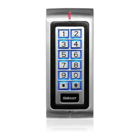
Other Sebury Keypad manuals
Popular Keypad manuals by other brands
DMP Electronics
DMP Electronics 9863 installation guide
GE
GE NX-148E - Security NetworX LCD Keypad user manual
UTC Fire and Security
UTC Fire and Security interlogix QS1500 installation instructions

Dolphin
Dolphin DOLGDO315390 instructions
Genie
Genie Wireless Keypad instructions
CAMDEN
CAMDEN CV-6268W installation instructions
