Euromag MC608 Series User manual

CAREFULLY READ THESE INSTRUCTIONS AND KEEP THEM IN A SAFE PLACE
TD 210-2-ENG
ENGLISH
Translate of the original instruction
Instruction manual
Version 6.0 and later versions - Ed. 10/2018
MC608 Converter
ELECTROMAGNETIC FLOW METERS

EUROMAG | MC608 | Ed. 10/2018
2 / 60
EUROMAG | MC608 | Ed. 10/2018
2 / 60
MC608
READ THE INSTRUCTIONS CAREFULLY AND KEEP THEM IN A SAFE PLACE
This manual can be downloaded from the web site www.euromag.com in the Area Download section.
We want you to save time and money!
We assure you that, having read this manual thoroughly, you will be able to perform correct installation
and fully use the product in total safety.
This document must be delivered to the user before machine installation and commissioning.
Symbols used in this manual
In order to draw the attention of all personnel working with the equipment supplied by EUROMAG
INTERNATIONAL, the points of particular importance described in this manual are highlighted with
graphic signs and different colors that will make them easily identiable.
Legend
CAUTION! This sign indicates a risk of electric shock! All operations marked with this sign must
be performed exclusively by qualied technical personnel.
CAUTION/WARNING. This symbol indicates vital information and points to be observed. Please
refer to the related documents.
NOTE. This symbol indicates information and points of particular importance to be observed.

MC608 SUMMARY 0
EUROMAG | MC608 | Ed. 10/2018
3 / 60
EUROMAG | MC608 | Ed. 10/2018
3 / 60
1 INTRODUCTION 5
1.1 MANUFACTURER’S STATEMENT............................................................................................... 5
1.2 PACKAGING VERIFICATION....................................................................................................... 5
1.3 PRELIMINARY NOTES ................................................................................................................ 6
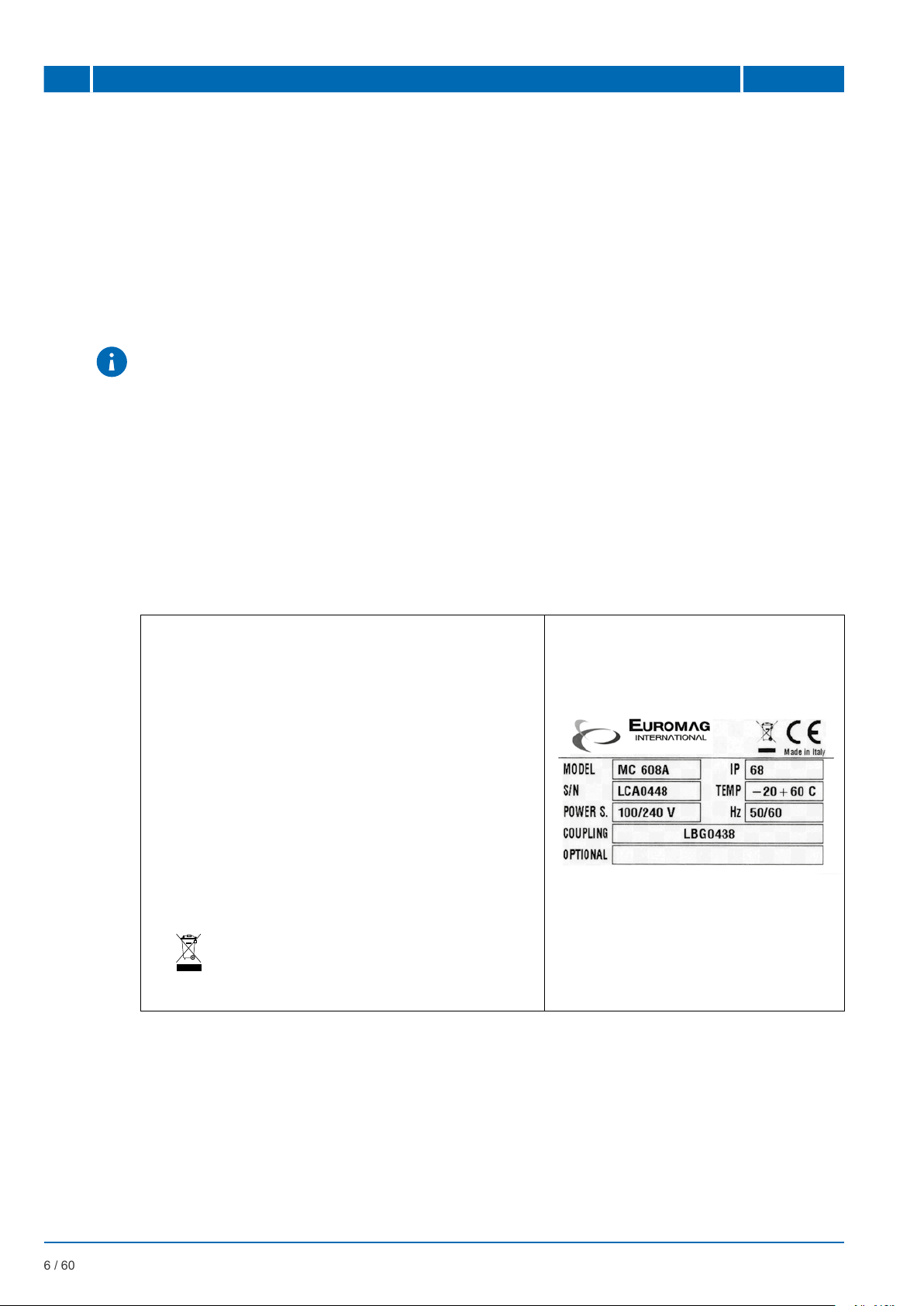
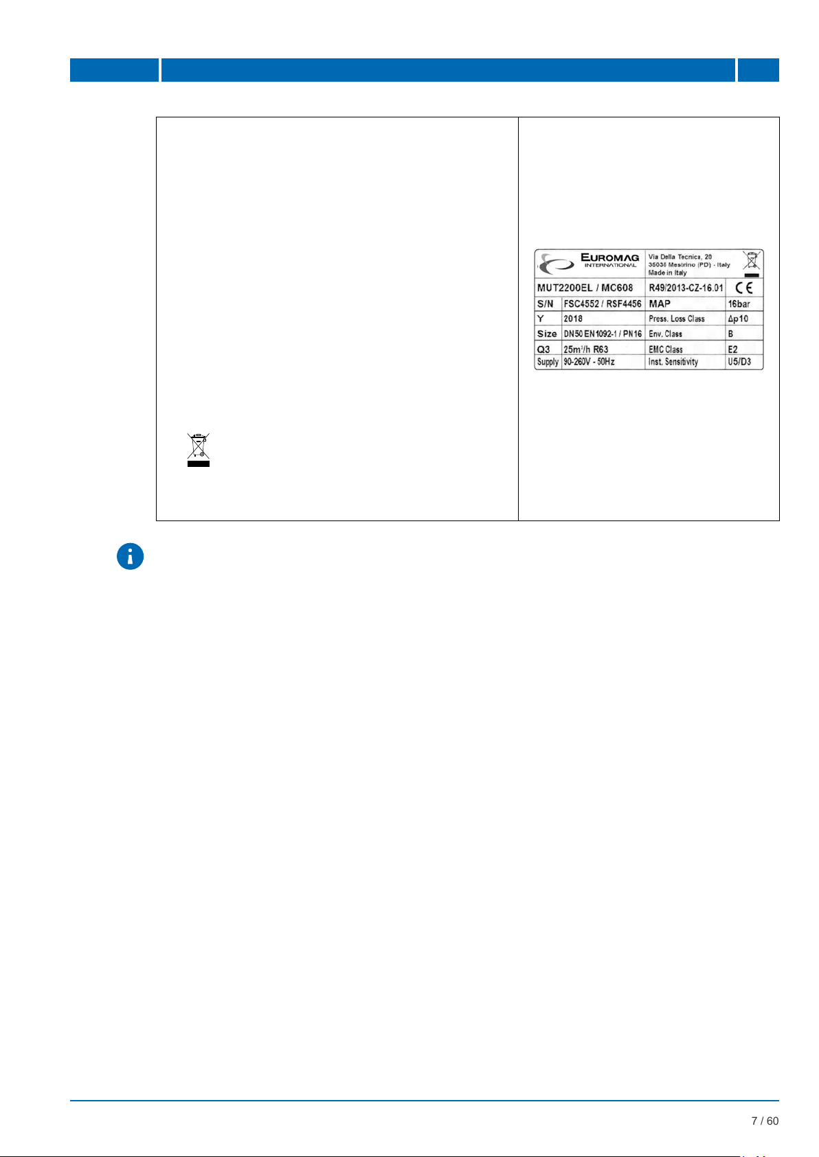
1.4 PRODUCT IDENTIFICATION....................................................................................................... 6
1.5 APPLICATIONS............................................................................................................................ 7
2 PRODUCT DESCRIPTION 8
2.1 OPERATING PRINCIPLE ............................................................................................................. 8
2.2 AVAILABLE VERSIONS ............................................................................................................... 8
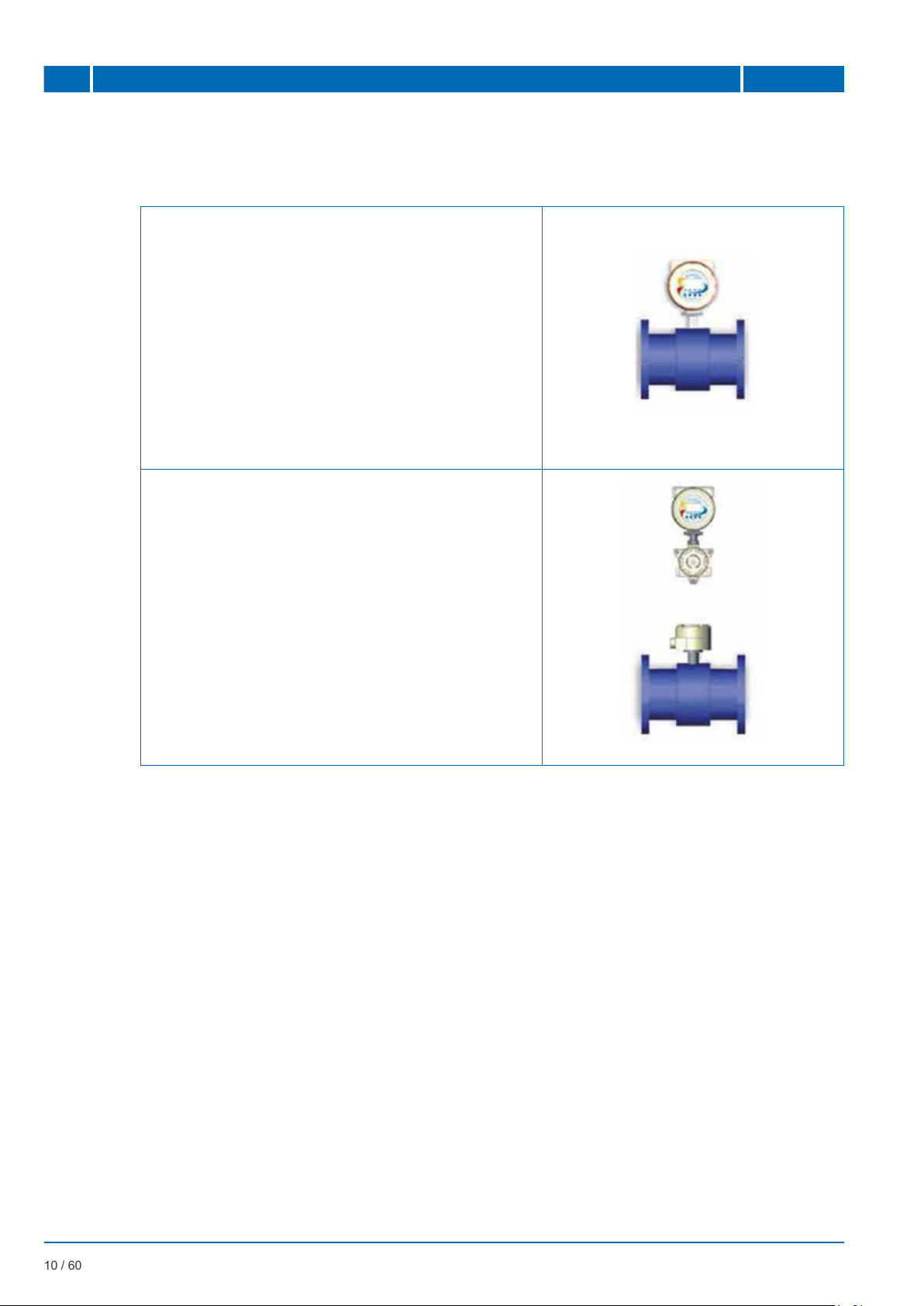
2.3 CONVERTER INSTALLATION TYPES ...................................................................................... 10
2.4 CASING ...................................................................................................................................... 10
2.5 POWER BATTERIES.................................................................................................................. 10
2.6 DATA SAFETY ............................................................................................................................ 11
2.7 REMOTE DATA READING ......................................................................................................... 12
2.8 OPTIONAL MODULES ............................................................................................................... 12
2.8.1 Hart protocol available for MC608A............................................................................................ 12
2.8.2 Optional module Pression/Temperature for MC608A. ................................................................ 12
3 TECHNICAL SPECIFICATIONS 13
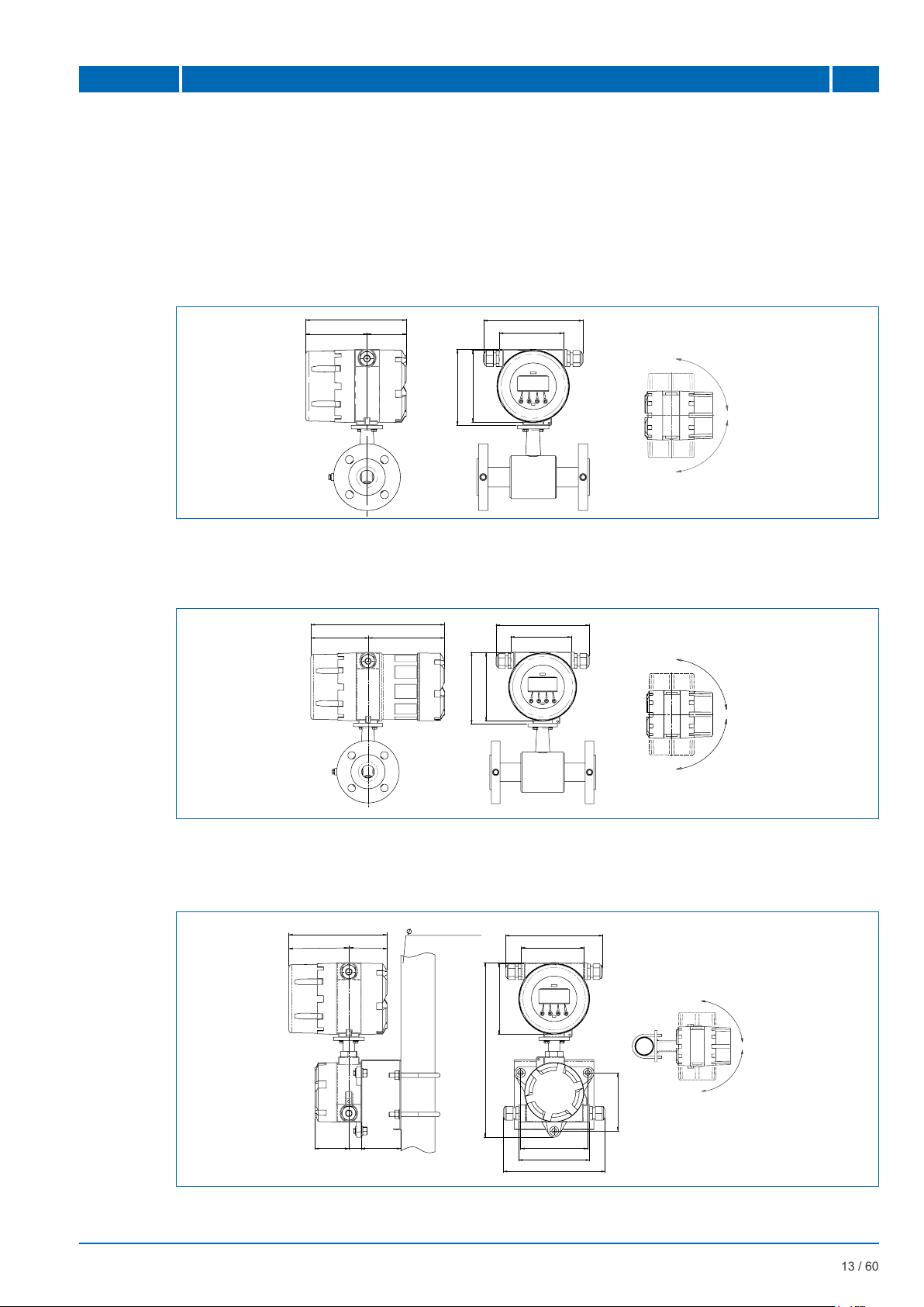
3.1 OVERALL DIMENSION .............................................................................................................. 13
3.1.1 Version MC608A (COMPACT) .................................................................................................... 13
3.1.2 Version MC608B/R (COMPACT) ................................................................................................ 13
3.1.3 Version MC608A (REMOTE) ...................................................................................................... 13
3.1.4 Version MC608B/R (REMOTE)................................................................................................... 14
3.1.5 Version MC608P (REMOTE) ...................................................................................................... 14
3.1.6 Version MC608I (REMOTE)........................................................................................................ 14
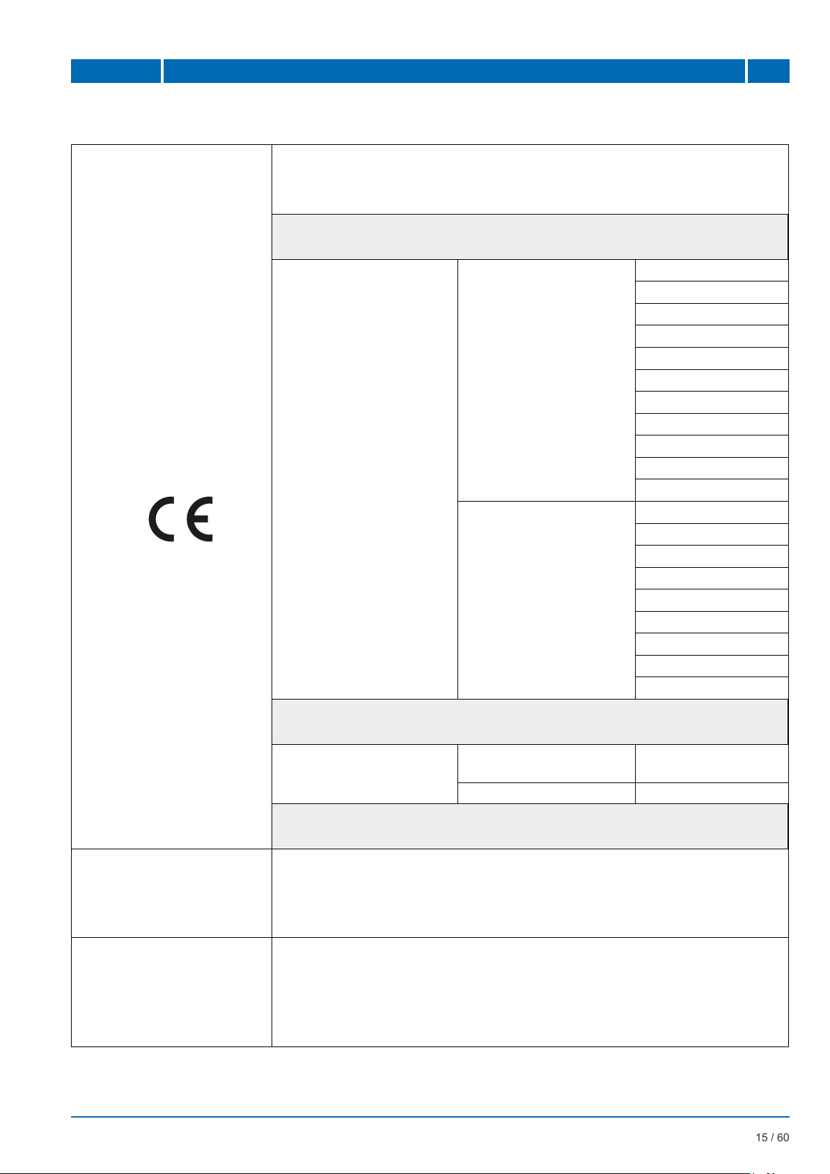
3.2 CERTIFICATES AND APPROVALS............................................................................................ 15
3.3 GENERAL TECHNICAL FEATURES.......................................................................................... 16
3.4 ACCURACY................................................................................................................................ 18
3.4.1 Reference conditions: ................................................................................................................. 18
4 INSTALLATION 20
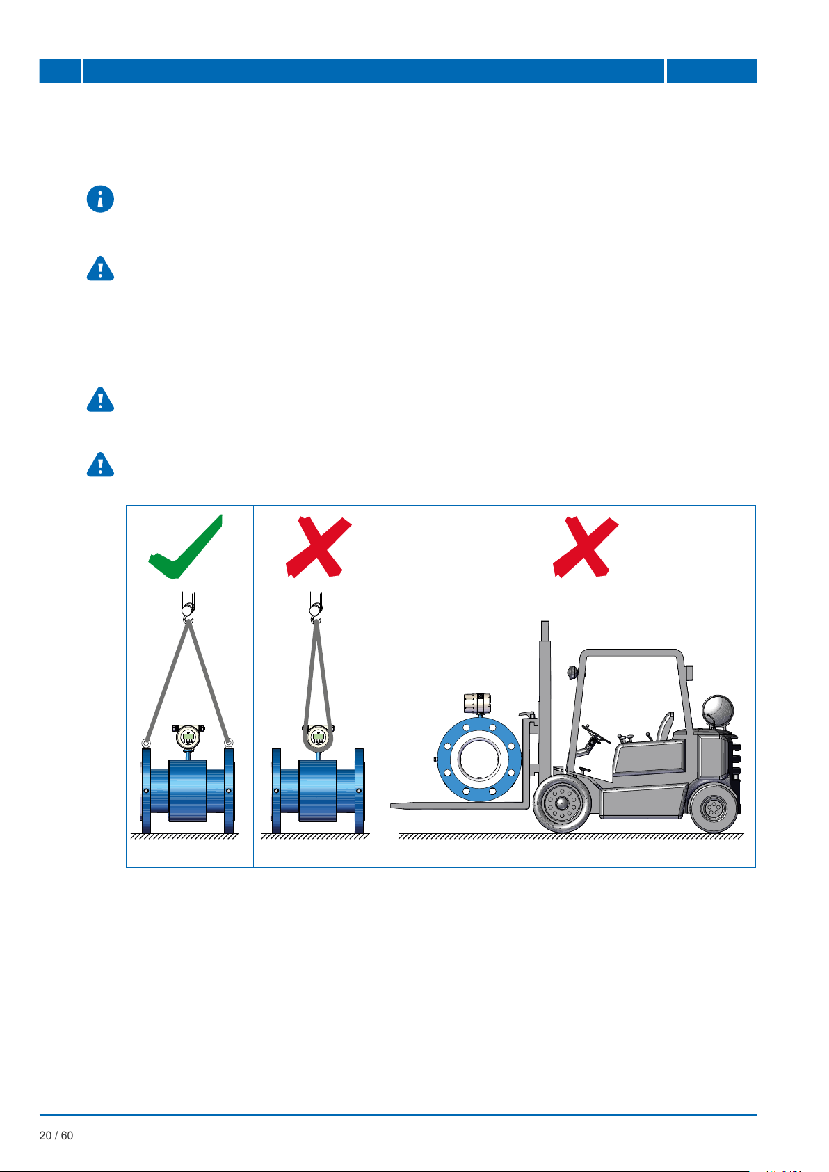
4.1 MOVING ..................................................................................................................................... 20
4.2 CONVERTER POSITIONINIG.................................................................................................... 21
4.2.1 Positioning/installation of the converter in COMPACT version ................................................... 21
4.2.2 Positioning/installation of the converter in REMOTE version...................................................... 22
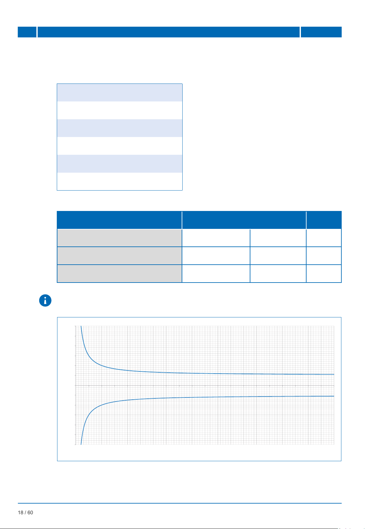
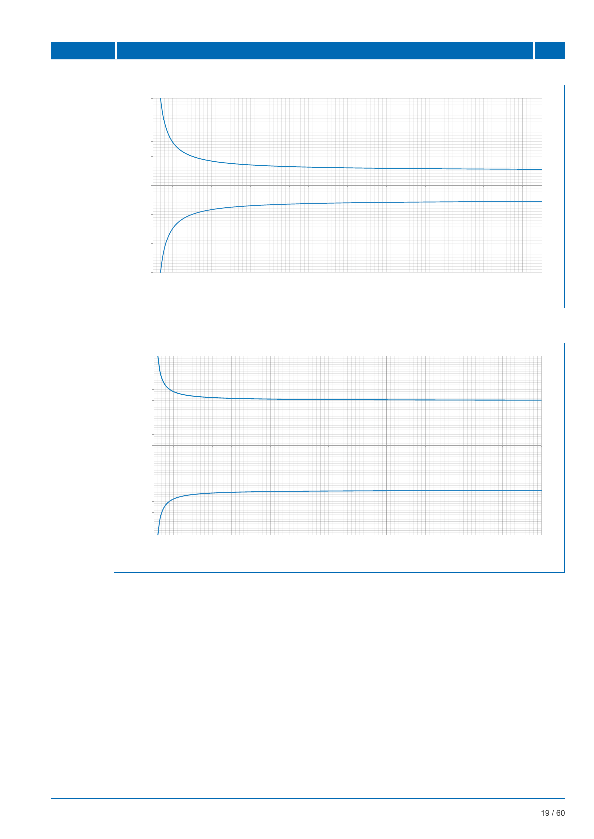
4.2.3 Relation between conductivity and cable length......................................................................... 23
4.2.4 Installation of the solar panel on MC608R in the COMPACT version......................................... 24
4.3 ELECTRICAL CONNECTION..................................................................................................... 25
4.3.1 Wiring diagram............................................................................................................................ 25
4.3.2 Connection to the sensor............................................................................................................ 27
4.3.3 Connection options I/O ............................................................................................................... 27
4.3.3.1 Pulse output................................................................................................................................ 27
4.3.3.2 Programmable output ................................................................................................................. 28
4.3.3.3 Output 4…20mA ......................................................................................................................... 29
4.3.3.4 MODBUS RS485 interface ......................................................................................................... 29
4.3.4 Electrical grounding of the converter .......................................................................................... 30

0 SUMMARY MC608
EUROMAG | MC608 | Ed. 10/2018
4 / 60
EUROMAG | MC608 | Ed. 10/2018
4 / 60
4.3.5 Connection to the power supply.................................................................................................. 31
5 MC608 CONVERTER PROGRAMMING 32
5.1 CONVERTER CONFIGURATION METHODS............................................................................ 32
5.1.1 Software MC608 conguration.................................................................................................... 32
5.1.2 Converter Password .................................................................................................................. 33
5.2 PROGRAMMING........................................................................................................................ 34
5.2.1 Data display description.............................................................................................................. 35
5.2.2 Status icons identication and description.................................................................................. 36
5.2.3 Device programming/conguration menu ................................................................................... 36
5.3 MENU ITEMS DESCRIPTION.................................................................................................... 39
5.3.1 MENU → PREFERENCES......................................................................................................... 39
5.3.2 MENU → COUNTERS................................................................................................................ 41
5.3.3 MENU → PARAMETERS ........................................................................................................... 42
5.3.4 MENU → I/O............................................................................................................................... 44
5.3.5 MENU → OTHER ....................................................................................................................... 46
5.3.6 MENU → MEMORY.................................................................................................................... 47
6 MAINTENANCE 49
6.1 CABLE GLAND CLOSING AND GASKET CONDITION CHECK .............................................. 49
6.2 BATTERY INSTALLATION/REPLACEMENT ON MC608B/R..................................................... 49
7 TROUBLESHOOTING 51
7.1 MALFUNCTIONING AND POSSIBLE SOLUTIONS................................................................... 51
7.2 ALARM MESSAGES SOLUTION............................................................................................... 53
8 SENDING THE CONVERTER (COMPACT VERSION) TO THE MANUFACTURER 54
8.1 REPAIR REQUEST FORM......................................................................................................... 54
9 PRODUCT DISPOSAL 56

EUROMAG | MC608 | Ed. 10/2018
5 / 60
MC608 INTRODUCTION 1
1 INTRODUCTION
IMPORTANT WARNING! It is very important that all personnel working with the equipment have
read and understood the instructions and indications provided in this manual, and that they
follow them prior to using the equipment itself. The manufacturer assumes no responsibility for
the consequences resulting from improper use by the worker.
The suitability of the device for particular purposes shall be worker’s responsibility.
The warranty will be considered void in case of improper installation and use of devices (systems).
• The manufacturer shall bear no responsibility for any damage caused by improper use, improper
installation or tampering of own products. Installation, connection, commissioning and maintenance
must be carried out by personnel who are qualied and authorized for this purpose. The personnel
in charge of the installation must make sure that the measurement system is properly connected as
per the wiring diagram indicated in this document.
• The manufacturer shall bear no responsibility for any damages or injuries resulting from any
misunderstanding of this manual. In order to avoid possible accidents to persons or things caused
by incorrect interpretation of the instructions, the user must not proceed with operations and/or
interventions on the converter if there are uncertainties or doubts regarding the operation(s) to be
performed. We recommend contacting Assistance Service for clarications in this regard for more
precise instructions.
• The manufacturer will be held responsible only if the converter will be used in its original conguration.
For applications that require high working pressures or use of substances that may be dangerous
for people, the environment, equipment or anything else: In case of pipe breakage, EUROMAG
INTERNATIONAL recommends to take the necessary precautions such as adequate positioning,
protection or installation of a guard or safety valve, before installing the CONVERTER in the COMPACT
version.
The device contains live electrical components, therefore installation, checks and maintenance must be
carried out by experienced and qualied personnel who are aware of all necessary precautions to be
taken. Before opening any internal part, please disconnect the power supply.
1.1 MANUFACTURER’S STATEMENT
»Stresses and loads possibly caused by earthquakes, strong winds, re damage, vibrations and
natural disasters were not taken into account in the phase of machine designing.
»Do not install the machine in such a way that it acts as a focus for stresses on the pipes. External
loads were not taken into account in the device conguration.
»While the device is working, the pressure, supply voltage and/or temperature values indicated on
the label or in this Operating Manual must not be exceeded.
1.2 PACKAGING VERIFICATION
At the moment of purchase and/or upon receipt of the product, the buyer is strongly advised to check the
quality of the packaging which must be intact, without visible dents and completely and correctly closed.
When opening the packaging, also check that the product complies with the information on the packing
list in terms of completeness of components/accessories.
NOTE: All EUROMAG INTERNATIONAL software packages are available on the USB ash drive
key that accompanies the product.
The software can also be downloaded from the website www.euromag.com by accessing the
Download Area. A free registration will be required after which you can download the conguration
software for your product.

EUROMAG | MC608 | Ed. 10/2018
6 / 60
1 INTRODUCTION MC608
1.3 PRELIMINARY NOTES
Main parts of the electromagnetic owmeter are:
»Sensor – installed in the tube with the use of anges and other joints;
»Converter – can be installed on the sensor (in compact version) or remotely (in remote version)
connected with two pipes.
Electromagnetic owmeters have many important advantages compared to their mechanical counterparts,
such as: exceptional long-term stability, maximum process reliability and zero maintenance. As a result,
these sensors can provide accurate and reliable long-term measurements.
See the following paragraphs for more detailed information on correct installation.
NOTES:
Electromagnetic owmeters are designed specically to operate under the following basic
conditions:
1. The liquid must be conductive
2. The tube must always be completely full
3. The input and output distances must be on recommended settings
4. The grounding instructions must be followed
1.4 PRODUCT IDENTIFICATION
Each MC608 Converter manufactured by EUROMAG INTERNATIONAL has a STANDARD identication
plate (Fig. 1) or OIML (Fig. 2), that displays the following information:
STANDARD PLATE:
»CE conformity mark.
»MODEL: converter model.
»IP: converter protection class.
»S/N: serial number which identies the device.
»TEMP: minimum/maximum temperature of the
working conditions.
»POWER S.: power supply or battery voltage
(MC608B).
»Hz: power supply frequency.
»COUPLING: serial number which identies the
sensor connected to the converter.
»OPTIONAL: other modules can be added.
»: This symbol means that the product must be
disposed of according to the legal requirements.
Fig. 1 STANDARD Identication Plate

EUROMAG | MC608 | Ed. 10/2018
7 / 60
MC608 INTRODUCTION 1
OIML PLATE:
»CE conformity mark
»MUT2200EL/...: sensor/converter model.
»S/N: sensor/converter serial number.
»Y: production year.
»Size: diameter of the ange.
»Q3: permanent ow rate and ratio.
»Supply: voltage and frequency.
»R49/2013...: reference certicate.
»MAP: maximum allowable pressure.
»Press Loss Class: pressure loss class.
»Env. Class: environmental class.
»EMC Class: EMC class.
»Inst. Sensitivity: installation sensitivity class
»: This symbol means that the product must
be disposed of in accordance with the legal
requirements.
Fig. 2 OIML
The identication plate must never be removed, damaged or changed. It must also be kept
clean from any dirt deposits, as the data contained are the only safe and unambiguous way to
recognize the type of converter and be able to complete the repair request form attached to this
manual.
1.5 APPLICATIONS
MC608 is widely used for purposes in which it is important to measure the ow rate of electrically
conductive liquids. Examples of typical applications for the MC608 converter are:
»Extraction and distribution points
»District-level measures
»Irrigation
»Wastewater treatment systems
»Leak detection systems
»Remote applications without access to electrical grid

EUROMAG | MC608 | Ed. 10/2018
8 / 60
2 PRODUCT DESCRIPTION MC608
2 PRODUCT DESCRIPTION
2.1 OPERATING PRINCIPLE
MC608 converter has been designed with the aim of fulllment of all the requirements of modern water
management systems, through a exible and hybrid electronics which, depending on the model, offers
various power supply solutions.
An electromotive force is induced at the ends of
a conducting uid that moves with velocity v in a
magnetic induction eld B and can be expressed as:
e = kBDv
Where it is:
B is constant by construction;
Dis constant and represents the
distance between the electrodes E1
and E2 (equivalent to the diameter
of the owmeter);
v is the uid velocity;
k is the calibration constant;
1 - Electromotive force (proportional to the velocity);
2 - Electrodes;
3 - Magnetic eld;
4 - Coils;
1
2 4
3
emf «e» is proportional to the velocity «v»
2.2 AVAILABLE VERSIONS
The MC608 converter is available in 5 versions, and can cover all the different types of applications
depending on the category of system to be monitored.
Specically, EUROMAG INTERNATIONAL produces the converter in the following versions:
MC608A
Power 12/24 Vac-dc or 90/264 Vac.
Aluminium casing.

EUROMAG | MC608 | Ed. 10/2018
9 / 60
MC608 PRODUCT DESCRIPTION 2
MC608B
Battery powered with useful life up to 10 years
(maximum diameter DN600 with integrated ow
meters).
Aluminium casing.
MC608R
Rechargeable battery powered, with solar panel
(maximum diameter DN600 with integrated ow
meters).
Aluminium casing.
MC608P
Power at 12/24 Vac-dc.
Version with a panel.
Polycarbonate casing.
MC608I
Power at 12/24 Vac-dc o 90/264 Vac with internal
back-up battery or rechargeable battery with solar
panel.
Stainless steel casing.

EUROMAG | MC608 | Ed. 10/2018
10 / 60
2 PRODUCT DESCRIPTION MC608
2.3 CONVERTER INSTALLATION TYPES
Depending on the version of the MC608 converter, it can be installed in the system in two different ways:
• COMPACT (Fig. 3): The converter is mounted to
the relevant detection sensor.
Fig. 3 Compact Version
• REMOTE (Fig. 4): The converter, if powered from
the mains (MC608A/P/I) can be installed up to
100 meters away from the sensor while battery-
powered converter (MC608B/R) can be installed up
to a maximum of 30 meters away from the sensor.
Fig. 4 Remote version
2.4 CASING
The MC608 converter is protected by suitable casing specically chosen for each product version. In
particular, protective casings can be:
»Solid and reliable casing in aluminium IP68 for MC608A/B/R
»Stainless steel IP54 casing for MC608I for remote installations
»Solid thermoplastic casing for installations in electrical cabinets MC608P
2.5 POWER BATTERIES
The MC608B and MC608R converters are battery-powered via a primary lithium battery as well as a
rechargeable lithium battery. It is therefore necessary to consider the following:
»Lithium batteries are the primary energy source because of their high-energy density, and are
created to meet the highest safety standards. However, they can be potentially hazardous if they
are exposed to electrical or mechanical abuse. In many cases, this is associated with excessive
heat production in which the increased internal pressure could lead to cell rupture.

EUROMAG | MC608 | Ed. 10/2018
11 / 60
MC608 PRODUCT DESCRIPTION 2
These basic precautions need to be followed when handling and using lithium batteries:
IMPORTANT INSTRUCTIONS!
• Do not short-circuit, recharge, overload or reverse-connect the battery
• Do not expose the battery to temperatures higher than those specied, as it will incinerate
• Do not crush, puncture or open the cells or disassemble the battery packs
• Do not weld or braze the battery body or battery packs
• Do not expose the contents to water
The use of lithium batteries is regulated under the United Nations Model Regulations on the Transport
of Dangerous Goods (UN Model Regulations on the Transport of Dangerous Goods), document ST/SG/
AC.10/1 Rev. 20.
These are basic precautions that should be followed during the transport of lithium batteries:
IMPORTANT NOTES!
• Transport only in special packages with labels and special transport documents specic to
current regulations.
• Be careful when handling, transporting and packing the batteries so as to avoid short-
circuiting.
• The batteries comply with the requirements set out in the “UN Manual of Tests and Criteria,
Part III, subsection 38.3” for air transport and with the provisions of the ADR regulations for
transport by truck/ship.
Remove the battery from the transmitter before sending the ow meter to EUROMAG
INTERNATIONAL in case of maintenance or any intervention under warranty.
2.6 DATA SAFETY
All versions of the MC608 converter guarantee safety of the collected and processed data as a
result of the internal memory (EEPROM) on which the data are saved.
The integrated circulating memory allows the storage of data with 200,000 log lines (the data are kept
for more than 6 years with factory settings); when the memory is full, the new data will automatically
overwrite the old data.
In order to prevent the loss of saved data, and to be able to better manage it on its management
systems, the unit is supplied with a specialized software that allows users to communicate with the
electronics of the MC608 via IrCOM or RS485 Modbus serial interfaces, that can be connected to any
PC, laptop and/or tablet with a Windows operating system.
Fast download, data management, easy programming and an advanced self-diagnosis system, that
automatically perform a wide range of essential checks, make the MC608 converter a highly efcient
and irreplaceable tool for uid detection in water management systems.
A multi-level password system also allows controlled access to the data collected and guarantees
condentiality.

EUROMAG | MC608 | Ed. 10/2018
12 / 60
2 PRODUCT DESCRIPTION MC608
2.7 REMOTE DATA READING
The GSM module allows data collection on site and remote monitoring via the GSM/GPRS network and
allows any client to access all the information easily and without any cost. An additional communication
module automatically sends the information via SMS, e-mail (with or without attachment) and to the free
access site www.euromagdata.com, using any browser and entering personal ID and password. This
option is available also on smartphones and tablets.
For more information on the GSM module, refer to document TD 211.
2.8 OPTIONAL MODULES
2.8.1 Hart protocol available for MC608A.
The MC608A/I converter can be equipped with an optional module (installable only by the manufacturer)
which acquires the Hart connectivity on the 4-20mAoutput, granting the access to all quantities measured
by the device as well as to the operating parameters. A MC608 converter equipped with Hart connectivity
has no Modbus connectivity on RS485.
For more information on Hart, refer to the relevant documentation.
2.8.2 Optional module Pression/Temperature for MC608A.
All the versions of the MC608 converter can be equipped with an optional module (installable only by
manufacturer) to which one or two wired probes are connected that allow the device to measure the
pressure and temperature of the process. This information, in addition to being stored in the internal data
logger, can be directly viewed on the display (Para.5.2.1, p.34), is accessible via Modbus / Hart and is
transmitted by the GSM module (if installed) in the manner laid out by the same device.

EUROMAG | MC608 | Ed. 10/2018
13 / 60
MC608 TECHNICAL SPECIFICATIONS 3
3 TECHNICAL SPECIFICATIONS
3.1 OVERALL DIMENSION
The overall dimensions of single versions of the MC608 converters are shown below.
3.1.1 Version MC608A (COMPACT)
170,85173
67,5 111
105,5
90°
90°
Ø 125
131
Fig. 5 Dimensions MC608A (Compact)
3.1.2 Version MC608B/R (COMPACT)
170,85247
141,5 111
105,5
Ø 125
131
90°
90°
Fig. 6 Dimensions MC608B/R (Compact)
3.1.3 Version MC608A (REMOTE)
2" Mounting Pole
173
67,5105,5
170,85
111
Ø 125
307
90°
90°
60 22 70 118
125
178,85
102
Fig. 7 Dimensions MC608A (REMOTE)

EUROMAG | MC608 | Ed. 10/2018
14 / 60
3 TECHNICAL SPECIFICATIONS MC608
3.1.4 Version MC608B/R (REMOTE)
170,85
111
Ø 125
307
90°
90°
118
125
178,85
102
60 22 70
2" Mounting Pole
247
141,5105,5
Fig. 8 Dimensions MC608B/R (Remote)
3.1.5 Version MC608P (REMOTE)
102,45
10,50 91,95
130
120
183,40
127,50
Mounting clamps Panel mounting plate
Fig. 9 Dimensions MC608P (Remote)
3.1.6 Version MC608I (REMOTE)
303
202 201
288
Fig. 10 Dimensions MC608I (Remote)

EUROMAG | MC608 | Ed. 10/2018
15 / 60
MC608 TECHNICAL SPECIFICATIONS 3
3.2 CERTIFICATES AND APPROVALS
MARKING
The device, connected to the relevant sensor, complies with the requirements
of the applicable EU directives. These are listed together with the applied stan-
dards in the relevant EU Declaration of Conformity..
Electromagnetic compatibility
Directive 2014/30/UE
Harmonised standards:
For all the versions:
EN 61326-1
EN 55011
EN 61000-3-3
EN 61000-4-2
EN 61000-4-3
EN 61000-4-4
EN 61000-4-5
EN 61000-4-6
EN 61000-4-8
EN 61000-4-11
For GSM versions
ETSI EN 301 489-1
ETSI EN 301 489-7
ETSI EN 301 489-17
ETSI EN 301 489-24
EN 55022
EN 61000-3-2
ETSI EN 301 511
ETSI EN 301 908-1
ETSI EN 301 908-2
Electrical safety
Directive 2014/35/EU
Harmonised standards:
For the versions without
GSM: EN 61010-1
For GSM versions: EN 60950-1
RoHS
Directive 2011/65/UE
Certicates and
international standards
ISO 20456: Measurement of uid ow in closed conduits
IEC 60529: Degrees of protection provided by enclosures (IP Code)
HART: HART 7 Protocol
OIML R49: Water meters intended for the metering of cold potable water
NMI M 10: Meters Intended for the Metering of Water in Full Flowing Pipes
Sensor certications
Depending on the sensor connected to the MC608 converter, other certications
could be applicable; refer to the documentation on the specic sensor for more
information:
ATEX / IECEx: Directive 2014/34/EU - IEC 60079 - 0, IEC 60079 - 18
Use in potable water: DM 174 6/4/2004, NSF / ANSI61, WRAS, FDA
Coating for aggressive environments: ISO 12944-2

EUROMAG | MC608 | Ed. 10/2018
16 / 60
3 TECHNICAL SPECIFICATIONS MC608
3.3 GENERAL TECHNICAL FEATURES
The table below contains the technical data of the MC608 converter in all versions produced by
EUROMAG INTERNATIONAL.
Features MC608A MC608B MC608R MC608P MC608I
Casing
Aluminium
IP68
Aluminium
IP68
Aluminium
IP68
Technopolymer
IP54
SS
IP54
Power supply
90...264 Vac √ √***
12/24 Vac/dc √ √ √
Battery powered [estimated
useful life: up to 10 years] √
Rechargeable battery +
photovoltaic panel √ √
Installation
Compact √√√
Remote max 100m max 30m max 30m max 100m max 100m
Consumption 5W÷10W
Uscite I/O
Analog output 4-20mA √√
loop powered
loop powered if
in battery mode √ √
Output AUX 24Vdc
max 30mA √ √ ** √ √
Transistor output for pulses
max 1000 Hz duty cycle
max 50% only for positive
instantaneous ow rate,
positive negative (max 500
pulses/ second)
√√√√√
Digital programmable output
for:
• Reverse ow
• Max ow rate threshold
• Min ow rate threshold
• Max/min ow rate
threshold
• Dosing
• Interrupted excitation
• Empty pipe
√ ** √ √
Digital output in active freq.
0-10 kHz √ ** √ √
All the outputs are opto-isolated.
* = Optional | ** = Only in rechargeable version | *** Possibility to have a backup battery

EUROMAG | MC608 | Ed. 10/2018
17 / 60
MC608 TECHNICAL SPECIFICATIONS 3
Features MC608A MC608B MC608R MC608P MC608I
Serial
communications
IrCOM interface √√√√√
RS 485 - MODBUS RTU √ ** √ √
Hart* communication √ √
Integrated GSM/GPRS
module* √ √ √
* = Optional | ** = Only in rechargeable version
Display
Graphic LCD 128x64 px,
viewable area 50x25mm,
white backlight
√√√√√
Programming
Through 4 onboard buttons
Through IRCOM / RS485 in-
terface with relevant softwa-
re
√√√√√
Process memory Memory 4 MB ash,
200.000 data lines √√√√√
Metrological
certicate OIML R49-1: 2013 - Class 2
Optional
(depends on
the connected
sensor)
Temperature elds
• Environment: -20 ÷ 60 °C (-4 ÷ +140 °F)
• Liquid: -25 ÷ 80 °C (-13 ÷ +176 °F)
• Storage: -40 ÷ 70 °C (-40 ÷ +158 °F)
Unit of measurement ml, cl,dl, l, dal, hl, m3, Ml, in3, ft3, gal, bbl, oz, g, hg, kg, q, t, lb, Aft
Optional modules GSM/GPRS
Pressure (1 input) and temperature (1 input)
Totalizers 5 (2 positive, 2 negative, 1 NET)
Alarms and status icons Status icons displayed and alarms recorded in the data logger
Self-check
Available alarms:
• Excitation failure
• Empty pipe with fourth electrode
• Excessive ambient temperature
• Overlapping pulses
• Measurement error
• Insufcient supply voltage
External check Availability of the eld verier for calibration and on-site electronics status check
Software for communication and
programming
Commissioning (same setting of the meters) - Data printing for documentation - Data
export (in CSV format) - Firmware update - Instantaneous ow rate reading - Reading and
writing of non-volatile parameters - Internal data logger download - Display of stored events
Signal cables • EUROMAG INTERNATIONAL cables:
• CA22 – cables for sensors with four electrodes
Pressure sensor 0...20 Bar; 1/8” GAS male, connector with factory installed y coupling
Temperature sensor PT500: includes thermowell of 1/4”, length 50mm, diameter 6mm

EUROMAG | MC608 | Ed. 10/2018
18 / 60
3 TECHNICAL SPECIFICATIONS MC608
3.4 ACCURACY
3.4.1 Reference conditions:
• Measuring liquid: water
• Conductivity: >200 µs/cm
• Temperature: 20°C / 68°F
• Pressure: 1 bar / 14,5 psi
• Upstream diameter: ≥ 5 DN
• Downstream diameter: ≥ 3 DN
Model Accuracy class Graphics
MC608A/P/I Class 02 2 ±0,2 % ± 2mm/s Fig. 10
MC608B/R Class 05 5 ±0,5 % ± 5mm/s Fig. 11
MC608 connected to insertion sensor Class 2 2 ±2 % ± 2mm/s Fig. 12
The following accuracy class refers to the measurement conditions during the calibration at the
EUROMAG INTERNATIONAL test benches:
-1,20
-1,00
-0,80
-0,60
-0,40
-0,20
0,00
0,20
0,40
0,60
0,80
1,00
1,20
0,0 0,5 1,0 1,5 2,0 2,5 3,0 3,5 4,0 4,5 5,0 5,5 6,0 6,5 7,0 7,5 8,0 8,5 9,0 9,5 10,0
Error [%]
Speed [m/s]
CLASS 02 2
Fig. 11

EUROMAG | MC608 | Ed. 10/2018
19 / 60
MC608 TECHNICAL SPECIFICATIONS 3
-3,00
-2,50
-2,00
-1,50
-1,00
-0,50
0,00
0,50
1,00
1,50
2,00
2,50
3,00
0,00,51,01,52,02,53,03,54,04,55,05,56,06,57,07,58,08,59,09,510,0
Error [%]
Speed [m/s]
CLASS 05
Fig. 12
-4,00
-3,50
-3,00
-2,50
-2,00
-1,50
-1,00
-0,50
0,00
0,50
1,00
1,50
2,00
2,50
3,00
3,50
4,00
0,0 0,5 1,0 1,5 2,0 2,5 3,0 3,5 4,0 4,5 5,0 5,5 6,0 6,5 7,0 7,5 8,0 8,5 9,0 9,5 10,0
Error [%]
Speed [m/s]
CLASS 2 2
Fig. 13

EUROMAG | MC608 | Ed. 10/2018
20 / 60
4 INSTALLATION MC608
4 INSTALLATION
4.1 MOVING
Given the small size and the low weight of the REMOTE version of the MC608 converter, there are
no particular precautions/indications that need to be followed in order to carry out its movement
and/or installation at the place of use.
CAUTION! The compact version of the MC608 converter must be carefully moved so as not to
cause damage to the sensor and connection anges. Below you will nd a description of the
correct and incorrect handling of the compact converter.
The proper lifting method (for transport and installation) of the compact converter is shown in Fig. 14.
The ow meter must be lifted and transported by properly harnessing the device on the side parts of the
ow meter, making sure that the slings (ropes, bands, etc.) are xed to the appropriate eyebolts.
WARNING: Do not raise the ow meter harnessing the converter (Fig. 15)!!
Do not move the owmeter with the lifting device if it is not in the original packaging (Fig. 16) or
without an adequate support that ensures the required stability.
Fig. 14 Fig. 15 Fig. 16
Other manuals for MC608 Series
1
This manual suits for next models
5
Table of contents
Other Euromag Media Converter manuals