Secabo C30III User manual

OPERATING INSTRUCTIONS
for vinyl cutters
Secabo C30III, C60III and C120III
Congratulations on purchasing a Secabo vinyl cutter!
Please read these operating instructions thoroughly to ensure that you can start
production with your vinyl cutter without problems.
Reproduction of these operating instructions in any form requires written approval of
Secabo GmbH. e reserve all rights to change technical data and product features
without prior notice. Not liable for printing errors.
Secabo GmbH does not assume any liability for direct or indirect damage or injury
resulting from use of this product.
Version 3.1 (25.05.2010)

Table of Contents
Table of ContentsTable of Contents
Table of Contents
1
11
1
Safety Precautions
Safety PrecautionsSafety Precautions
Safety Precautions ................................
................................................................
................................................................
................................................................
...................................................
......................................
................... 2
22
2
2
22
2
Items Included
Items IncludedItems Included
Items Included ................................
................................................................
................................................................
................................................................
........................................................
................................................
........................ 3
33
3
3
33
3
Layout of Stand
Layout of StandLayout of Stand
Layout of Stand-
--
-Up
UpUp
Up-
--
-Base
BaseBase
Base................................
................................................................
................................................................
................................................................
..........................................
....................
.......... 4
44
4
4
44
4
Unit Description
Unit DescriptionUnit Description
Unit Description ................................
................................................................
................................................................
................................................................
......................................................
............................................
...................... 5
55
5
4.1
Unit Parts and Their Function.................................................................5
4.2
Side Views ...........................................................................................5
4.3
Control Panel.......................................................................................6
5
55
5
Starting Up Appliance and Software
Starting Up Appliance and SoftwareStarting Up Appliance and Software
Starting Up Appliance and Software ................................
................................................................
..........................................................
....................................................
.......................... 7
77
7
5.1
Installation Secabo FlexiStarter ..............................................................7
5.1.1
Version 8.6 with USB-Dongle...........................................................7
5.2
Connection via USB Interface ................................................................7
5.3
Connection via Serial Interface ..............................................................8
5.3.1
Be sure to check .............................................................................8
5.4
Starting Up Appliance...........................................................................9
5.5
Installing and Adjusting the Blade ..........................................................9
5.6
Inserting the Blade Holder...................................................................10
5.7
Inserting cutting vinyl ..........................................................................10
5.8
Cutting Test .......................................................................................11
6
66
6
Settings and Operation
Settings and OperationSettings and Operation
Settings and Operation ................................
................................................................
................................................................
................................................................
..........................................
....................
.......... 12
1212
12
6.1
Online/Offline ...................................................................................12
6.2
Moving the Cutting Head....................................................................12
6.3
Setting the Zero Point .........................................................................12
6.4
Changing ..........................................................................................13
6.5
Repeat Function .................................................................................13
6.6
Other Settings....................................................................................14
6.7
Limit Switches.....................................................................................14
7
77
7
LAPOS (just C60III and C120III as of Model 11/08)
LAPOS (just C60III and C120III as of Model 11/08)LAPOS (just C60III and C120III as of Model 11/08)
LAPOS (just C60III and C120III as of Model 11/08) ................................
................................................................
.................................
..
. 15
1515
15
7.1
One-time Calibration of LAPOS ..........................................................15
7.2
Application of LAPOS .........................................................................21
8
88
8
Drag knifes
Drag knifesDrag knifes
Drag knifes ................................
................................................................
................................................................
................................................................
...........................................................
......................................................
........................... 22
2222
22
9
99
9
Technical Data
Technical DataTechnical Data
Technical Data................................
................................................................
................................................................
................................................................
......................................................
............................................
...................... 23
2323
23
10
1010
10
Troubleshooting
TroubleshootingTroubleshooting
Troubleshooting ................................
................................................................
................................................................
................................................................
....................................................
........................................
.................... 24
2424
24

2
1Safety Precaut ons
Please read these instructions and safety precautions carefully before using your
vinyl cutter for the first time!
•Do not place any magnetic objects in the vicinity of the cutting head;
otherwise uniform contact pressure is not ensured.
•Do not remove the connection cable to the computer while plotting is in
progress.
•Relieve the pressure on the pressure rollers when not in use by moving the
pressure lever up.
•Do not reach into the unit with your hands when the power is connected.
•Never open the housing or attempt to modify the unit yourself.
•In case you are requested by the Secabo customer support to open the
heating plate cover, please make sure you are wearing respiratory protection
and only touch the contained insulation wool with gloves. Any disposal of the
wool must be contained in a closed bag.
•Ensure that liquids and metal objects do not get into the inside of the plotter.
•Ensure that the wall socket used is grounded and protected with a ground
fault switch.
•Ensure that the connected voltage (220V) does not deviate by more than
±10%. Otherwise install a voltage stabilizer.
•Disconnect the power cord when the unit is not used for a longer period of
time.
•Never reach into the unit in the vicinity of the blade holder during the cutting
operation!
•Discontinue any printing jobs in progress before readjusting the blade holder!
•Always ensure that the vinyl cutter is out of reach of children during operation
and never leave the unit or individual parts of it switched on without
supervision.
•Do not touch the tip of the sliding blade to avoid injury.
•Always place the unit on a stable base to prevent it from falling down.
•Do not operate the unit during thunderstorms; it can be damaged or
destroyed by lightning.

3
2Items Included
Before starting work, please check whether the following items are all present:
Item Quant ty
Power cable 1
Serial connection
cable 1
USB connection
cable 1
Bladeholder 1
Penholder 1
45° drag knife 3
Pens 2
Secabo FlexiStarter 1
Stand-up-base
(not with C30III)
1

4
3Layout of Stand-Up-Base
The stand-up base for your Secabo vinyl cutter can be assembled simply using the
parts supplied as shown in the exploded drawing above.

5
4Un t Descr pt on
4.1 Un t Parts and The r Funct on
4.2 S de V ews
USB-port, serial port
Power supply, fuse, switch
Blade Holder
Grid rollers
Control panel
Cutting head
with LAPOS
Laser

6
4.3 Control Panel
a) Online-/Offline button
b) Test button (blade test)
c) LCD display
d) Arrow keys for control of cutting head and for pulling in vinyl
e) Zero point button
f) Pause button (to interrupt plotting operation)
g) Repeat button for repeating a job
h) Menu button for appliance settings
d
c
b
a
h
g
f
e

7
5Start ng Up Appl ance and Software
Attent on! Please note that you need to nstall Flex Starter f rst to ensure a
smooth nstallat on and complete conf gurat on of your Secabo v nyl cutter.
5.1 Installat on Secabo Flex Starter
Version 8.6 of the FlexiStarter cutting software with USB-dongle is supplied with your
Secabo vinyl cutter. To control the vinyl cutter with your PC, install the software as
described below:
5.1.1 Vers on 8.6 w th USB-Dongle
•Plug the USB dongle (copy protection plug) supplied into the USB port
(installation is accomplished automatically).
•Insert the FlexiStarter CD supplied.
•Select the Desired Language in Setup and click Continue.
•Enter your user ident and 32-digit password on the rear of the software
cover.
•Start the installation program and select the desired language again.
•Read the software license agreement and accept.
•Set the check marks for the features Flexi/Production Manager/Samples and
click Continue.
•The copy operation is started = Installation in progress.
•Click finish
5.2 Connect on v a USB Interface
Your Secabo v nyl cutter has a USB nterface for connect on between your
PC and v nyl cutter.
Please note that your Secabo v nyl cutter can be operated only w th
W ndows 2000 or W ndows XP. Use w th W ndows 95 / 98 / Me s not
poss ble.
The unit is equipped with a USB-RS232 adapter to ensure that your Secabo vinyl
cutter also functions with cutting programs which can only control the peripheral
devices over a serial or parallel interface. This installs a virtual serial interface on
your PC under COM1 or COM2.
•Before connecting the vinyl cutter to your PC, first install the appropriate
drivers from the driver CD provided by running the SETUP.EXE file. Click
"Install".

8
•After installing, connect the vinyl cutter to the USB interface on your PC using
the USB cable provided. indows then indicates that new hardware
components have been recognized and shows when the installation is
completed.
•To determine the number assigned to the new interface, it is necessary to call
the Windo s Device Manager. For this purpose, click on Workplace with the
right mouse key and select Properties. Then select the Hard are tab in the
window which opens and click Device Manger. The serial and parallel
interfaces on the computer are listed under the point Connections, including
the USB To Serial connection. The interface number (e.g. COM1) indicated
following the connection is the connection number to be used (e.g. in Artcut).
•If it is necessary to change the connection number, proceed as follows: Click
the connection with the right mouse key and select Properties.
•Then click Advanced on the Connection Settings tab and enter the new
number in the COM connection number field. This is required, for example,
when using cutting programs such as Artcut, because Artcut can control vinyl
cutters only over the COM1 or COM2 interface.
5.3 Connect on v a Ser al Interface
No special installation is required when you connect your Secabo vinyl cutter to the
hardware-side serial interface on your PC; it is only necessary to connect the plotter
to the interface using the cable provided.
5.3.1 Be sure to check
Be sure to check the following settings before starting the first time:
•Open the FlexiStarter cutting software.
•Create your inscription or graphic and click Cut/plot file. In order to use Date
from CorelDra , the graphic must be exported from CorelDra as EPS and
can be opened in FlexiStarter via File / Open.
•Select your Secabo vinyl cutter (C30III, C60III or C120III).
•In the Production Manager go to Settings / Job standard settings / cutting
options, knife offset and enter a value between 0,020cm and 0,033cm.
•Activate the overcut option with a value of 0,0254cm in the File - Cut/Plot -
Advanced menu. If your vinyl cutter is controlled directly, please select local
PC.
•Set the flo control to Xon/Xoff in the properties and set the baud rate to
38400. Set the baud rate both in the software and in the machine‘s menu. In
version 8.5, you can select the baud rate and flow control in the production
manager by clicking the knife symbol in the left area of the window.
9
•In FlexiStarter under Edit / Settings / Tools / Plotting and cutting, remove the
check mark in front of Connect to local Production Manager over TCP/IP
(applies only for users on local PC).
CAUTION! These sett ngs must be made before start ng a plott ng job; they
do not become effect ve for plott ng jobs already act ve!
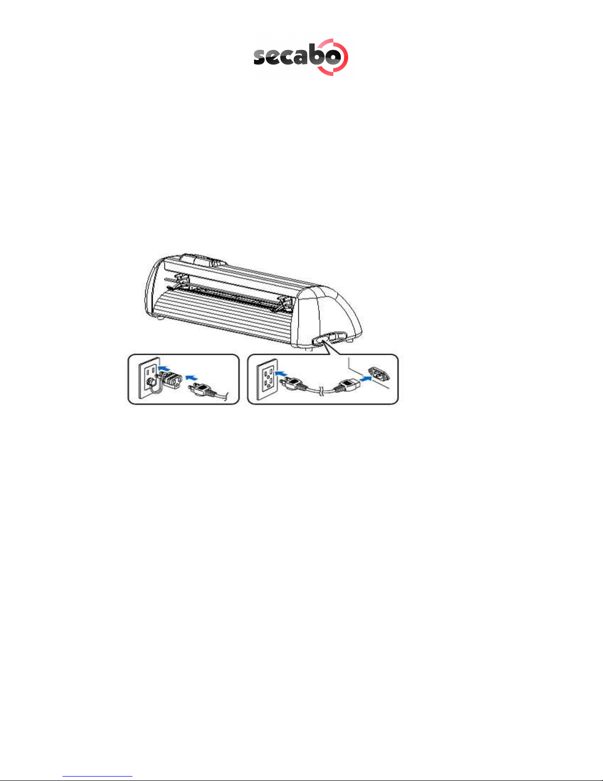
5.4 Start ng Up Appl ance
Ensure that sufficient space is present for the vinyl transport in front of and in back
of the unit. The vinyl cutter should be operated only in clean and dry surroundings.
•Connect the plotter to a 220 V wall socket with the power cable provided.
•Then switch the plotter on. Caution! After switching on, the cutting head
initially moves to the right.
5.5 Install ng and Adjust ng the Blade
•Take one of the cutting blades supplied and place it in the blade holder so
that the sharp side extends at the front. The blade is held by a magnet in the
blade holder.
•Adjust the cutting depths by turning the front cap.
•The depth is initially set correctly when you can carefully move your fingertip
across the blade and feel only a light scratching. Since the depth adjustment
for the blade depends on the material, it may be necessary to change it later
(as a rule 0.05 mm to 0.1 mm).
•Press the pin on the rear of the blade holder to remove and replace the blade
at any time. Caution – Injury hazard!
The various material thicknesses require different blade settings or even special
blades; it may therefore be necessary to repeat the adjustment described above.

10
5.6 Insert ng the Blade Holder
•First turn the clamping screw for the blade holder on the cutting head until it
is open wide enough.
•Then insert the blade holder from the top and press down against the stop in
the hole on the right side and retighten the clamping screw
5.7 Insert ng cutt ng v nyl
•Always insert the material to be printed into the unit from the rear.
•Pull the vinyl up to the cutting bar in order to correctly set the zero point.
Details on setting the zero point are given under Point 6.3 in these
instructions.
•If you use a roll of vinyl instead of vinyl sheets, the vinyl can be rolled off
cleanly with the aid of the roll holder supplied.
•hen inserting, ensure that the vinyl is inserted straight to prevent it from
distorting during transport. hen the vinyl is inserted at an angle of only a
few millimeters, this can lead to the vinyl running highly off center during long
plotting jobs.
•You can insert the vinyl into the plotter at any desired point as long as the
pressure rollers are located in the areas of the yellow arrows on the cross-
member.
Mount the pinch rollers by switching the locking lever. Make sure the pinch rollers
are located on the edges of the vinyl (about 2cm inward) to ensure the vinyl is
tracking correctly and a maximum cutting area is ensured
.
Blade holder
Knurled screw

11
5.8 Cutt ng Test
•To perform the cutting test in the offline mode, press the Test button; the
plotter then cuts a rectangle in the inserted vinyl at the currently stored zero
point.
•You can check the adjustment of the blade holder as well as the contact
pressure with this cutting test. The material inserted should be cut cleanly and
straight during the cutting test; the backing material should not be damaged.
•If the backing material has been cut through, either the contact pressure is set
too high or the blade or blade holder is adjusted incorrectly. Change these
adjustments and perform the cutting test again.
•Also readjust if the vinyl was cut imprecisely or to an insufficient depth.

12
6Sett ngs and Operat on
6.1 Onl ne/Offl ne
After switching on the unit a reset is performed and the unit switches to the online
mode. You can switch back and forth between the online and offline mode by
pressing the Online button on the control panel. During the cutting operation, the
vinyl cutter must generally be in the online mode, to change the configuration
settings, the unit must be offline.
6.2 Mov ng the Cutt ng Head
In the offline mode, the cutting head can be moved to the right and left by pressing
the arrow keys and the vinyl can be moved forwards and backwards. The
corresponding X and Y coordinates are shown on the display.
6.3 Sett ng the Zero Po nt
Move the cutting head and vinyl so that the blade is at the front right corner of the
vinyl to set the correct starting point for plotting. Then confirm this zero point by
pressing the crosshair symbol in the middle of the control panel.
Online
OnlineOnline
Online-Status
Offline
OfflineOffline
Offline-Status
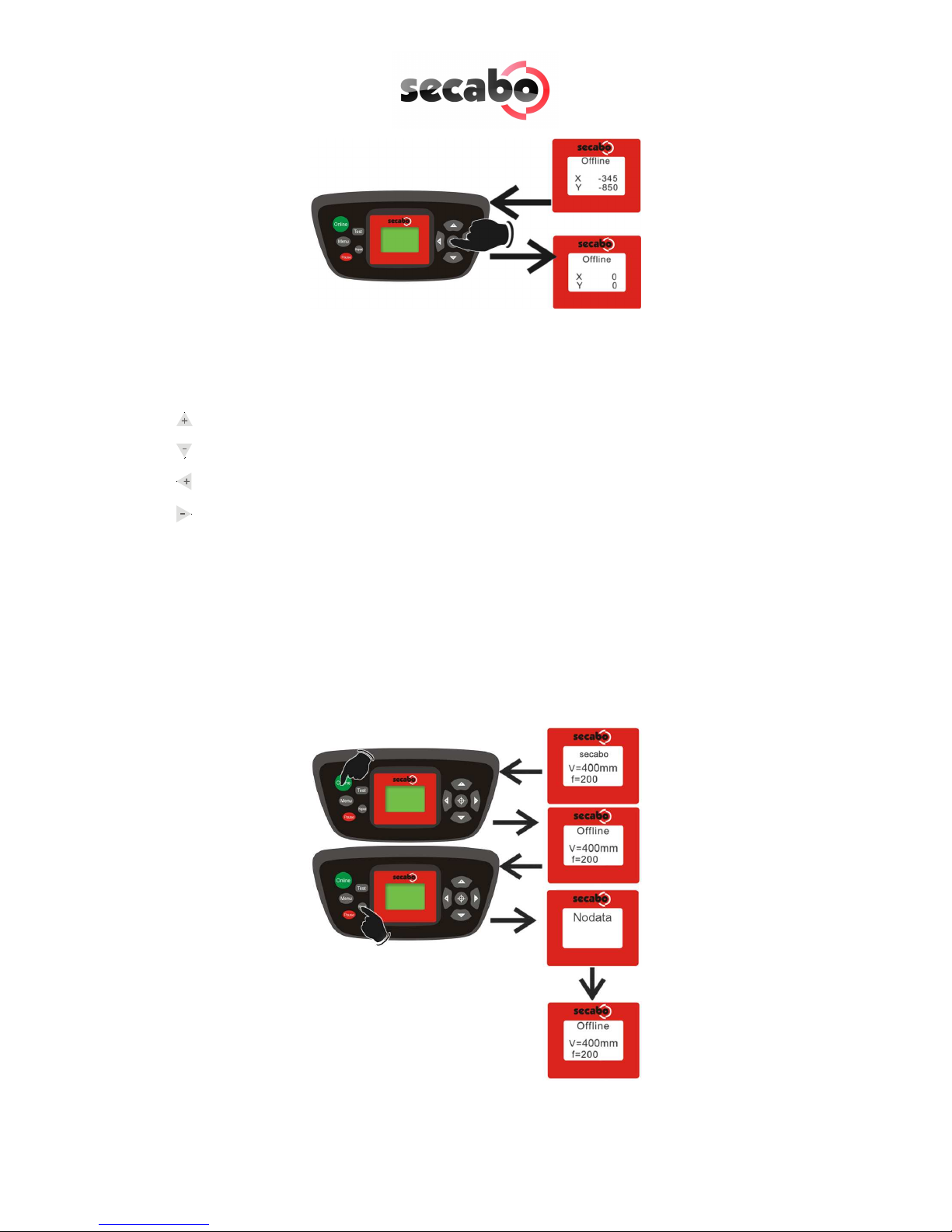
13
6.4 Chang ng
You can make the following changes in the online mode by pressing the
corresponding buttons:
Increase speed
Reduce speed
Increase pressure
Reduce pressure
The cutting speed and contact pressure cannot be changed while a plotting job is in
progress.
6.5 Repeat Funct on
After conclusion of a job it can be repeated without having to transfer the data from
the computer again. For this purpose ensure that the vinyl cutter is in the offline
mode and press the Repeat key.

14
6.6 Other Sett ngs
It is possible to scroll through other configuration menus in the offline mode by
pressing the menu key a number of times.
In the settings menu it is possible to adjust the idle speed of the cutting head (Ur), as
well as the Baud rate (Br). The Baud rate set must be identical with the Baud rate set
on the computer. This value must be set to 38400.
The vinyl cutter can be calibrated correctly in the scaling menu (Set Per). Correction
may be required here due to wear to the mechanical parts. The X and Y scaling of
the data can be changed by changing the Xp and Yp values. If, for example, an
object entered with a length of 100 cm on the computer is cut on the vinyl cutter to
a length of only 98cm, it is necessary to correct the corresponding scaling value on
the plotter.
Otherwise, these values should not be changed.
6.7 L m t Sw tches
If a plotting job is sent to the vinyl cutter accidentally which is larger than the
maximum cutting width of the plotter, the cutting head is stopped automatically by a
sensor at the left and right sides. In this case, the vinyl cutter is reset and it is
necessary to transfer the job to the plotter again.
38400

15
7LAPOS (just C60III and C120III as of Model 11/08)
LAPOS is a system for positioning printable media in your CIII cutting plotter so that
you can cut the printed elements in the designated contour without offset and free
from distortion.
The installation as well as the application of LAPOS is explained in the following
steps.
7.1 One-t me Cal brat on of LAPOS
Before you can do the first contour cut you have to calibrate LAPOS once in
connection with the FlexiStarter. This procedure is only to be repeated if you want to
use your FlexiStarter on a new PC.
For calibrating LAPOS please take the following steps:
•Open up a new document in your FlexiStarter.
•Construct a rectangle, size optional, but the width should not exceed 15 cm.
•hile highlighting the rectangle choose the menu point “Effects“ – “Contour
cutting“.
•In the appearing menu “DesignCentral“ you can now choose the position of
the cutting contour. As a rule you will enter a negative value of , e. g. “-

16
1mm“ so that the cut elements do not receive a white border later on. hile
calibrating it is best to use the value “0 mm“. Please confirm your entry by
clicking the green check mark on the bottom right in the menu.
•Now choose the menu “Effects“ – “Contour cutting mark“.
•Now you can choose whether two cutting marks horizontally or vertically shall
be set. ith small prints two marks are enough as they can be read in faster.
ith larger printed sheets 4 marks should be used to reach a higher
accuracy. Please confirm your entry by clicking the green check mark on the
bottom right of the menu.
Attention! After the setting of the marks the object cannot be scaled
Attention! After the setting of the marks the object cannot be scaled Attention! After the setting of the marks the object cannot be scaled
Attention! After the setting of the marks the object cannot be scaled
anymore!
anymore!anymore!
anymore!

17
•Now please click on the printer symbol in the top menu to print the object
according to the set marks with a printer of your choice. Please be careful
that the print is not scaled by the printer driver.
•Please place the print in the cutting plotter (if using paper its best on a
plotting pad) so that the set marks are located on the left above the cutting
head.
•Now choose the contour cutting function from the top menu.

18
•In the following window click on “Send“.
•Please confirm here with “OK“.
•A laser diode is now going to be activated on your Secabo cutting plotter.
ith help of the arrow keys lead this to the centre of the right cutting mark
(No. “1”). Please note that you must push one of the arrow keys within
several seconds to avoid the cutting plotter leaving the LAPOS modus
automatically.

19
•hen the laser is exactly in the middle of the cutting marks confirm with “Ok”
and continue the procedure with the second cutting mark.
Other manuals for C30III
1
This manual suits for next models
3
Table of contents


