NEW KON 112-905 User manual
O
Op
pe
er
ra
at
ti
in
ng
g
M
Ma
an
nu
ua
al
l
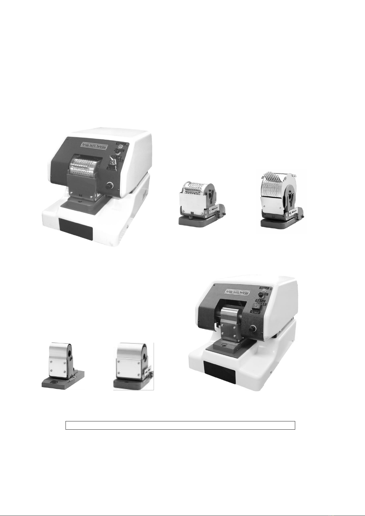
NEW KON ELECTRIC PERFORATORS
Models 112-905・112-905L・112-605・112-705
Final 04.18.2018
Die-Block
Pin Type Lever Type
MODEL:112-905 / 112-905L 905 905L
Die-Block
605 705 MODEL: 112-605 / 112-705
◆Specifications may change without prior notice for ongoing functional improvements.◆

1
N
NE
EW
W
K
KO
ON
N
I
IN
ND
DU
US
ST
TR
RI
IA
AL
L
C
CO
O.
.,
,
L
LT
TD
D.
.
C
Co
on
nt
te
en
nt
ts
s
◆Warning .........................................................2
◆Caution ..........................................................3
1.Appearance ......................................................4
2. Part names and accessories ........................................4/5
3. Operating parts and descriptions ...................................5/6
4.How to operate the die block ......................................6/7
5.Specifications ..................................................7/8
6.Operating methods ...............................................8/9
7.Perforating operation ...........................................9/10
8.Depth adjustments ................................................11
9.How to install and dismount the die block ..........................12/13
10.Troubleshooting ..............................................14/15
11.Maintenance & Cleaning .........................................15
2
Please be sure to read these precautions carefully before use.
Thank you for purchasing the
MODEL 112 Perforator
.For safety reasons, prior to operating
this machine, please read these precautions and operating manual carefully.
C
Ca
au
ut
ti
io
on
n
N
No
ot
ti
ic
ce
e
To use this machine correctly and in a safe manner, we added notifications to the following
sections to further explain important information. Please read the following carefully.
C
Ca
au
ut
ti
io
on
n
This mark indicates that if instructions are not followed, serious injury
and/or equipment damage may result.
C
Ca
au
ut
ti
io
on
n
1. Please be sure to use the electrical plug which is attached. Do not change the plug as it could cause fire
or electric shock.
2. DON’T disassemble or modify the power cord, otherwise, injury or electrical shock may occur.
3. If any abnormal state such as excessive heat, smoke or a bad smell occurs, IMMEDIATELY switch the main unit
OFF and remove the power cord from the outlet. Continuing to use it as is may lead to a fire or electrical shock.
4.
Should any foreign substances (metal, liquid, etc.) get inside the unit, IMMEDIATELY switch the main unit
OFF and remove power cord from the outlet. Continuing to use it as is may lead to fire or electrical shock.
Have the unit inspected/repaired by your authorized servicing dealer.
5. DON’T insert or remove a power supply adapter with wet hands as this may lead to an electrical shock.
6. BE SURE to detach the power cord from the outlet by holding its plug section, NOT the cord itself,
otherwise it might cause damage to the cord which could result in fire or electrical shock.
C
Ca
au
ut
ti
io
on
n
3
1. NEVER put your hands inside the machine as it may lead to bodily injury.
2. DON’T perforate materials other than paper as this might damage internal parts.
3. DON’T disassemble or modify the unit, otherwise injury or electrical shock may occur.
4. BE SURE to detach the power cord from the outlet before relocating the machine.
5. KEEP the unit out of children’s reach and do not let them operate it, otherwise injury may occur.
6. ALWAYS detach the power cord from the outlet if the unit is not to be used for extended periods.
C
Ca
au
ut
ti
io
on
n
S
Sa
af
fe
et
ty
y
P
Pr
re
ec
ca
au
ut
ti
io
on
ns
s
To ensure safe use of the machine and avoid damage to it,
please be sure to observe the following precautions.
Keep your fingers and hands away from the die block when perforating, otherwise injury may occur.
Don’t touch moving parts when perforating, otherwise injury may occur.
Don’t pull the paper out while perforating. Wait until perforation cycle is completed.
DON’T disassemble or modify the unit as it might cause a machine malfunction, possible injury,
fire or electric shock etc.
DON’T perforate materials other than paper such as metals: iron, copper, aluminum, stainless
steel, etc. This may result in damage to the die block and void manufacturer warranty.
DON’T perforate materials which adhere to the paper such as staples, paper clips, adhesive tape, etc.
This may result in damage to the die block and void manufacturer warranty.
DON’T perforate items such as wet paper, adhesion stickers, vinyl, etc. as these could cause
paper chips to clog the die block.
Perforated paper chips will accumulate in waste receptacle with frequent use of the perforator. Empty
it at regular intervals. Not emptying the waste will cause the paper particles to build up in the die block.
Please be sure to remove the plug from the outlet when removing the paper waste.
DON’T install the machine on an uneven or unstable surface as it could become susceptible
to falling off.
If you must move the machine, please carry it by the bottom of the main body with both hands.

4
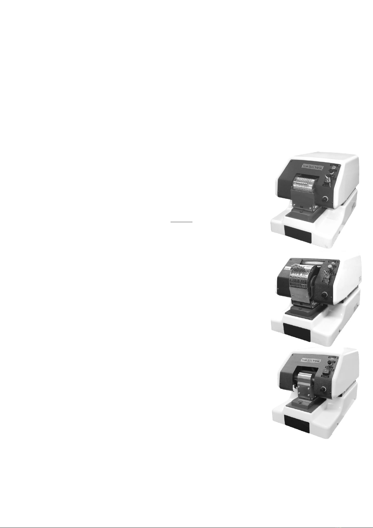
1
1.
.A
Ap
pp
pe
ea
ar
ra
an
nc
ce
e
2
2.
.P
Pa
ar
rt
t
n
na
am
me
es
s
a
an
nd
d
a
ac
cc
ce
es
ss
so
or
ri
ie
es
s
N
No
o.
.
P
Pa
ar
rt
t
N
Na
am
me
e
D
De
es
sc
cr
ri
ip
pt
ti
io
on
n
➀
Main Switch
The key switch turns on/off the power supply.
➁
Electric cord with plug
Plug unit into a suitable wall outlet.
➂
Power lamp
When the key switch is on, the power lamp will illuminate.
➃
Lock release button
Button to release die when the paper is jammed and machine has stopped.
➄
Fuse box
Turns off the power when an excessive electric load is applied to the product.
⑥
Waste Drawer
Drawer for paper chip storage. Must check and empty it frequently. It is
advisable to check and empty drawer daily.
⑦
Die block
This is the perforation die block.
⑧
Feed opening
Paper insertion area.
⑨
Top cover
Please remove the cover when you replace the die block.
⑩
Truss head screw
Screws for attaching the top cover.
⑪
Screws for fixing die block
Screws for attaching the die block.
Accessory
bag list
1 each Operating manual
1 each 6mm L shape
hexagonal wrench
2 keys
2 fuses; one is for power
(15A) and the other is for
PCB (1A)
5
3
3.
.O
Op
pe
er
ra
at
ti
in
ng
g
p
pa
ar
rt
ts
s
a
an
nd
d
d
de
es
sc
cr
ri
ip
pt
ti
io
on
ns
s
N
No
o.
.
P
Pa
ar
rt
t
N
Na
am
me
e
D
De
es
sc
cr
ri
ip
pt
ti
io
on
n
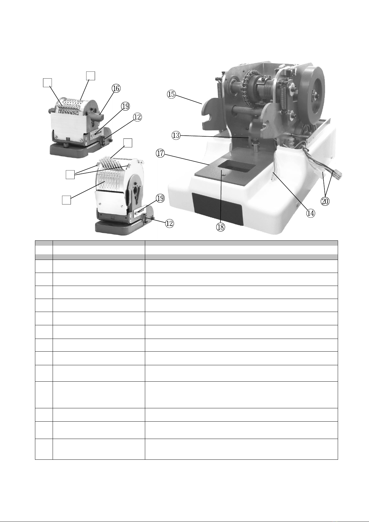
⑫
Micro switch
When switch is engaged by the edge of the paper, the machine will activate.
⑬
Bolt for fixing the stand.
Used for setting the die block on the main body.
⑭
Micro switch connector cables
Connectors for attaching micro switch.
⑮
Arm
Holds the die block shaft pin.
⑯
Shaft pin
For inserting into the die block.
⑰
Base
The base for installing the die block.
⑱
Alignment hole for die block
It is the screw hole for aligning the die block.
⑲
Depth gauge
Screw for adjusting the perforation depth.
⑳
Connector for main body cover
Connector to connect with the electrical operation section of the main
unit cover.
➊
Wheel
Numbers, letters and/or symbols are engraved.
※Character contents, except the standard date 8 digits and 10 digits,
(Varies depending on the customers’ requests.)
➋
Pin Select version
Pins that are used to select numbers, letters or logos.
➌
Lever Select version
Levers that are used to select numbers, letters or logos.
➍
Indicator
Used in Lever Select version to note correct position for proper
placement of perforation.
6
4
4.
.H
Ho
ow
w
t
to
o
o
op
pe
er
ra
at
te
e
t
th
he
e
d
di
ie
e
b
bl
lo
oc
ck
k
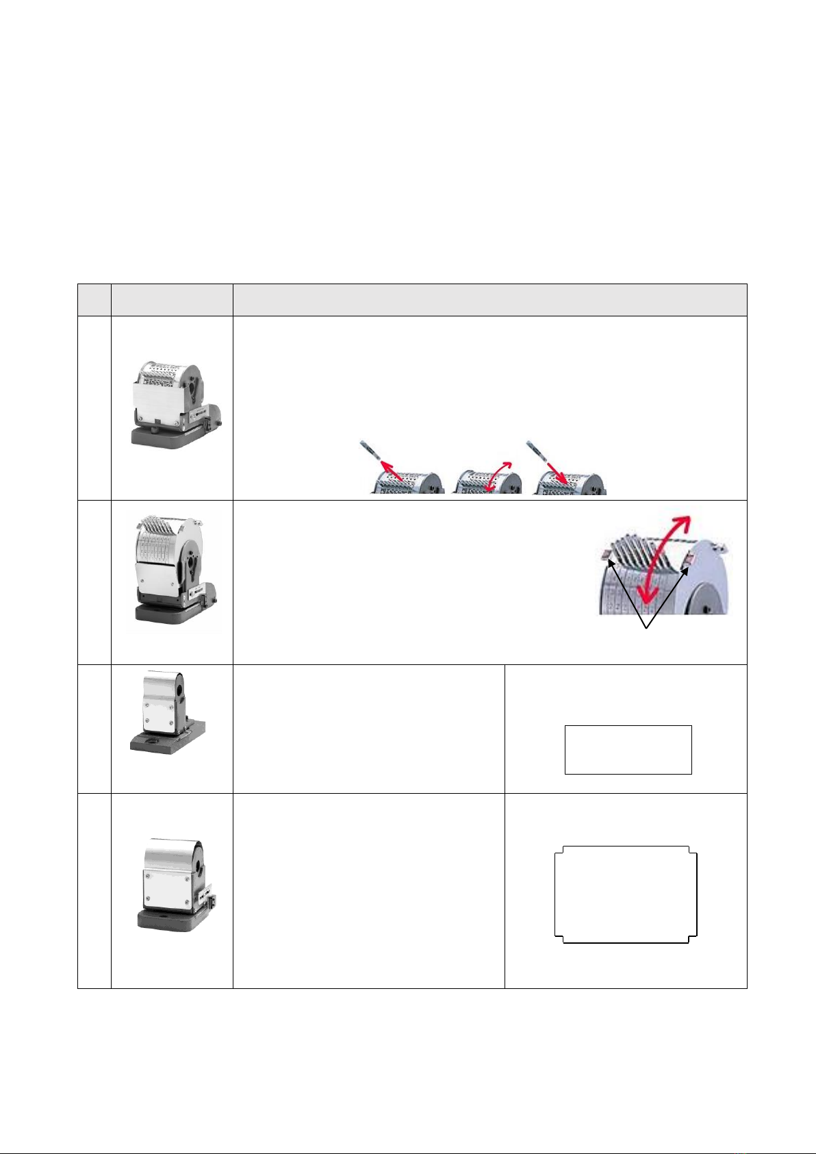
※There are 4 types of die blocks….905, 905L, 605 and 705.
※The maximum capacity is based on 64gs/㎡paper. Based upon paper thickness, number and diameter
of the needles, the specifications may vary. e.g: the capacity may be less than the specified maximum.
※All die blocks are equipped with a micro switch gauge for detecting the paper automatically.
The depth position can be changed by adjusting the depth gauge.
※Inserting the paper: when the edge of the paper engages the micro switch, the machine will start perforating.
N
No
o
N
Na
am
me
e
D
Di
ie
e
B
Bl
lo
oc
ck
k
O
Op
pe
er
ra
at
ti
io
on
n
①
【905】
PIN TYPE
■This is a pin style die block.
※Remove the pin, turn the wheel until you reach the desired position letter and insert the pin.
Note: please insert the pin securely and check that the wheel is not cycling.
If the wheel pin is not inserted securely, it will cause the needle to bend and the
corresponding hole in the base plate will be damaged.
Take out the pin → turn the wheel → check the wheel pin is inserted surely.
(Choose the letter-insert the pin )
②
【905L】
LEVER TYPE
■This is a lever type die block.
※Move the lever up or down to choose the desired letter or number
※The letters should match the indicator (red ▼).
If the indicator position and lever are matched, the position is correct.
Note: If the lever is not matched up with the indicator properly,
it will cause the needles to bend and the corresponding hole
in the base plate will be damaged.
【Indicator】
③
【605】
FIXED LETTER
■This is the die block for fixed letters.
※Designed at the customer
’
s request.
※It is a fixed die without the function for changing
letters or the design.
※If additional design or letters are requested,
another die block must be purchased.
【The dimension of the perforating range】
length 20mm × width 52mm
④
【705】
FIXED LETTER
■This is the die block for fixed letters.
※Designed at the customer
’
s request.
※It is a fixed die without the function for changing
letters or the design.
※If additional design or letters are requested,
another die block must be purchased.
【The dimension of the perforating range】
length 50mm × width 72mm
Note: not including 4corners(6mm×6mm)

7
5
5.
.S
Sp
pe
ec
ci
if
fi
ic
ca
at
ti
io
on
ns
s
Perforator Model
Model 112 Series Electric Perforator
Die Block Model
905
905L
605
705
Type of Selection Letter
PIN TYPE
LEVER TYPE
FIXED LETTER TYPE
Types of Perforations
Dating or numbering・1st line PAID・Custom
Fixed letters or marks
(including designed letters, logos, mark)
Perforating Range
8 digits・10 digits
(needle structure:4x6 holes)
20 x 52 mm.
50 x 72 mm.
Diameter of Needles
1.0 mm or 1.4 mm
Perforation Examples
Perforating Ability
30 sheets
※Dependent upon voltage, paper weight,
needle diameter & needle configuration
5-30 sheets.
※Dependent upon voltage, paper weight,
needle diameter & needle configuration
Perforating standard paper
Usual PPC paper (64 g/㎡)
Perforating Time
0.5 seconds/perforation (50Hz/ 60Hz)
Max Insertion Depth
※from edge of paper
Maximum insertion depth: 40 mm
Power Source
120V AC
Power Consumption
280W
Rated Frequency
50/60 Hz
Current Rating
6A
Rated Time
30 minutes
Fuse
15A
Dimensions (W×D×H)
277mm x 436 mm x 316mm
Weight
(including die block)
40.5 kg
42.5 kg
37.7 kg
38.7 kg

8
6
6.
.O
Op
pe
er
ra
at
ti
in
ng
g
m
me
et
th
ho
od
ds
s
■Please read the following precautions carefully before using.
1. Be sure to check and confirm that the power supply and voltage is correct as outlined in specifications.
2. When carrying the product, disconnect from the wall and please be sure to hold the bottom of the machine securely
with two or more people (more than one person) and move.
3. Since the perforator is very heavy (more than 30kg), be sure to place it on a solid surface.
4. Perforating capacity is based upon PPC paper (64 g /m2).
a. The perforating capacity of Die Block No.905 & No.905Lis approximately 30 sheets.
b. Depending upon voltage, paper weight, needle diameter & needle configuration, it is possible that the
maximum of 30 sheets per perforation will not be realized.
c. The capacity for Model No.605 and No.705 will be 5-30 sheets depending upon voltage, paper
weight, needle diameter & configuration.
5.Die Block Model No.905 (Pin Type)
To change the number or characters, please pull out the select pin and rotate the wheel freely with your
finger. When the engraved letter of each numeral, character or mark you wish to perforate is located,
insert the select pin into the number or character which is on the wheel. Please be sure that the select pin
is inserted into the wheel hole securely, otherwise it may cause the needles to bend and the wheel to
possibly sustain damage.
6. Die Block No.905L (Lever Type)
To change the number or character of the wheel, rotate the levers on the wheel up or down to the number
or character you wish to perforate. Please be sure to place the lever pin on the fixed position, otherwise it
may cause the it may cause the needles to bend and the wheel to possibly sustain damage. Once the lever
reaches the fixed position, you will feel it you will feel it lock into place.
7. Please don’t perforate any material except for paper.
Examples are as follows: metals (paper clips and staples), cloth products, leather products, seals, resins, etc.
8. Please empty the paper chip storage container on a regular basis as over-accumulation can cause problems
by compacting paper chips into the die block.
9. The machine is designed to start the perforation upon paper insertion. If the unit continues to activate on its’
own, please disconnect and contact your local servicing dealer for assistance.
10. If paper is jammed in the die block, please disconnect and contact your local servicing dealer for assistance.
11. Please don’t perforate in a previously perforated area. Change paper position for each new perforation.
12. Over time and based upon types of materials being perforated, some wear is to be expected. If the paper is
not being perforated thoroughly, please contact your local servicing dealer for assistance.
13. If you will not be using the perforator for an extended period, please remove the power plug from the wall.
9
7
7.
.P
Pe
er
rf
fo
or
ra
at
ti
in
ng
g
o
op
pe
er
ra
at
ti
io
on
n
■Precautions before use
※Please be sure to install the perforator on a solid surface.
※Perforators are very heavy. Please take caution while moving and setting up the unit with 2
or more persons.
※Please don’t insert the key into the power switch ➀until you are ready to perforate.
●For how to operate the die block, please refer to Page 6.
■
P
Pr
re
ep
pa
ar
ra
at
ti
io
on
n
f
fo
or
r
u
us
se
e
(
(P
Pi
in
n
S
St
ty
yl
le
e:
:
9
90
05
5)
)
1. Insert the power plug ②into an AC outlet.
2. Select the date or number that you wish to perforate.
※Remove the “select”pin ➋and rotate the wheel ➊
to the required number. Insert the “select”pin securely.
3. The perforation depth can be manipulated by adjusting the depth gauge ⑫.
※Please loosen the screw ⑬on the depth gauge ⑫and adjust to required position.
■
P
Pr
re
ep
pa
ar
ra
at
ti
io
on
n
f
fo
or
r
u
us
se
e
(
(L
Le
ev
ve
er
r
S
St
ty
yl
le
e:
:
9
90
05
5L
L)
)
1. Insert the power plug ②into the AC outlet.
2. Select the date or number that you wish to perforate.
※Move the “lever”pin ➌up or down the wheel ➊will turn and choose the
desired character. Select the number to match the right and left indicator ➍
In the desired position you can feel it lock into place.
3. The perforation depth can be manipulated by adjusting the depth gauge ⑫
※Please loosen the screw ⑬on the depth gauge ⑫and adjust to required position.
■
P
Pr
re
ep
pa
ar
ra
at
ti
io
on
n
f
fo
or
r
u
us
se
e
(
(F
Fi
ix
xe
ed
d
D
Di
ie
e:
:
6
60
05
5/
/7
70
05
5)
)
1. Insert the power plug ②into the AC outlet.
2. These dies are for fixed characters. There are no characters or dates to select.
3. The perforation depth can be manipulated by adjusting the depth gauge ⑫
※Please loosen the screw on the depth gauge and adjust to required position.
■There is a micro switch to auto activate the perforation cycle located
on the depth gauge.(Upon paper insertion, the machine will activate automatically.)
10
■Basic operation method of perforating (common to all series)
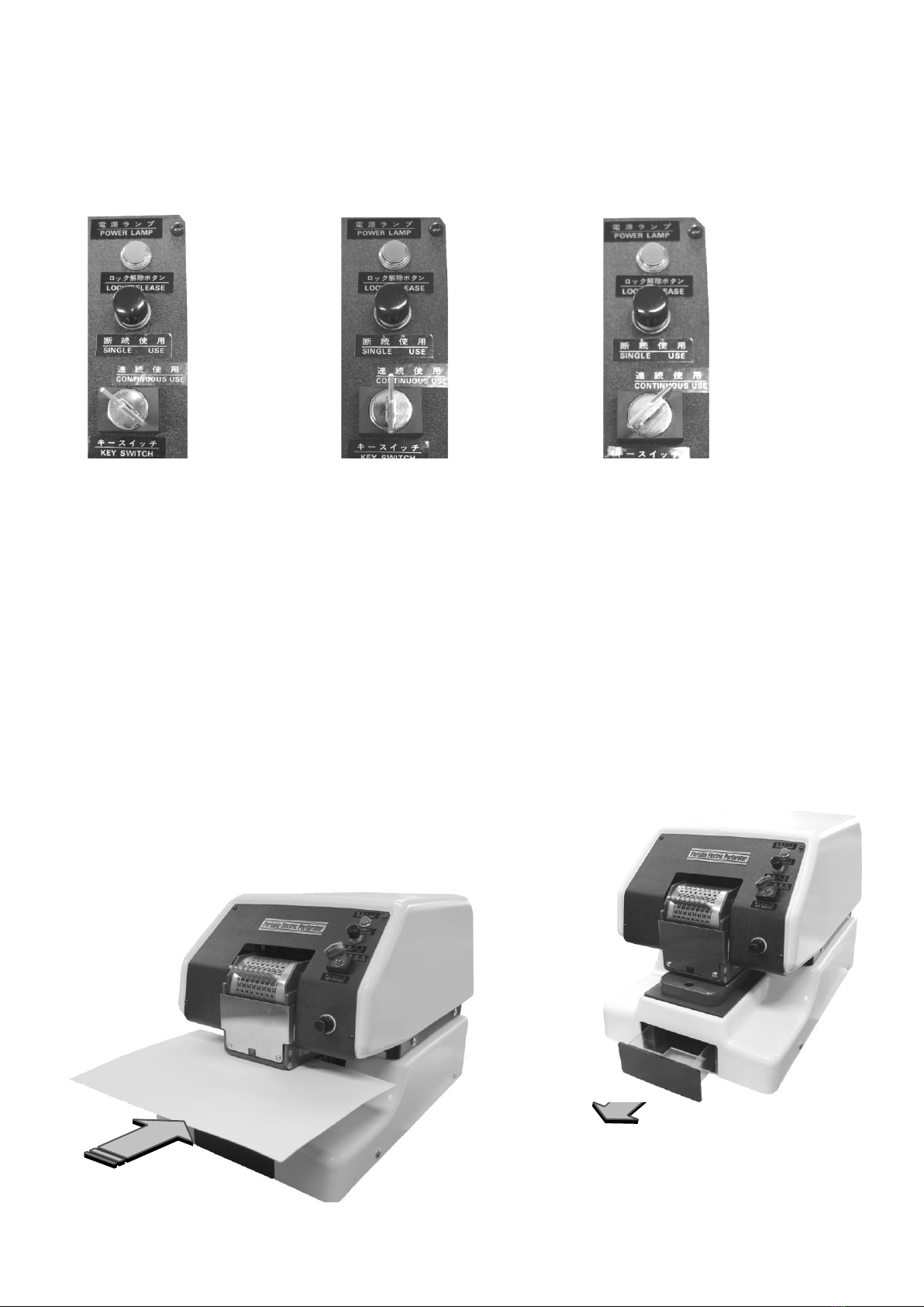
※This product has no power switch. Turn the key switch for turning on the power.
(Status of power lamp and key switch when operating the unit)
※The key of the power key switch ①can be plugged in or removed when it is in the left side position.
In the single use mode, the paper is inserted into the paper feed opening ⑧, when the depth switch ⑫
is pressed, the motor is activated, the perforating operation is started. When the perforating
operation is completed, the motor stops.
※Under continuous use mode, the motor will work continuously.
1. Turn the key switch ①to right side. (key in the middle:single use) (key in the right side:continuous use)
※Please refer to the above pictures.
Lamp ③lights green, the machine can perforate.
2. When inserting the paper into the feed opening ⑧, the edge of the paper will activate the depth micro switch and
the perforation process will begin.
3. Please pull out the paper after perforating.
4. The perforating is completed.
5. After every cycle, paper chips will accumulate in the paper chip storage container.
※Please clean the paper chip storage container on a regular basis. Accumulated
paper waste can clog the die if the container is not emptied regularly.
Light is off
Key is on the left side.
It is possible to insert
or remove the key
Light is on
Key is in the middle.
The machine is on
single use mode.
Light is on
Key is on the right
side. The machine is
set on continuous mode.
Please discard the paper waste frequently,
otherwise it will cause damage.
11
8
8.
.
D
De
ep
pt
th
h
A
Ad
dj
ju
us
st
tm
me
en
nt
ts
s
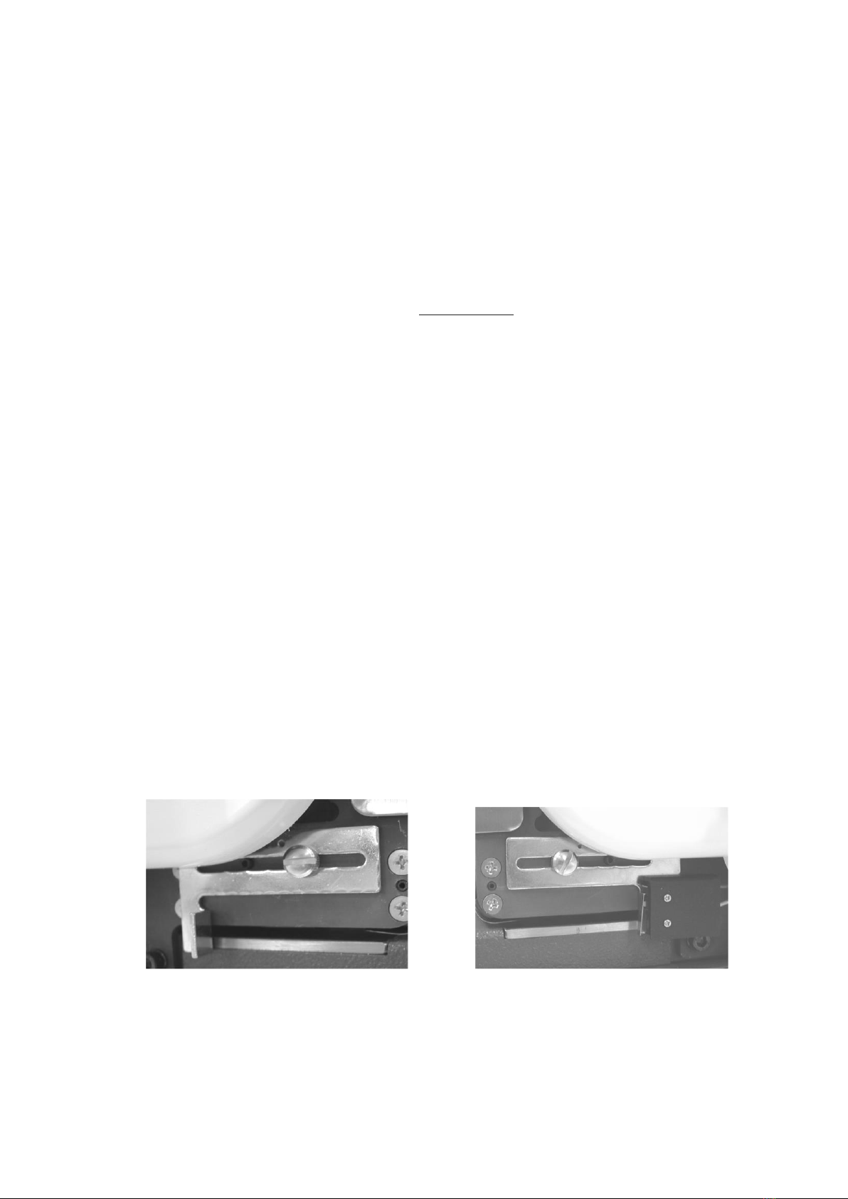
■There is a microswitch to auto-activate the perforation cycle located on the depth gauge.
(Upon paper insertion, the machine will activate automatically)
※The position of the micro switch is set at the point of maximum depth when shipped from the factory.
■If you need to change the depth, please adjust according to the following procedure.
※The microswitch is located on the depth gauge located on the right side of the die block.
Note: Please turn off the power when you adjust the depth.
Do not attempt to adjust the depth switch gauge on the left side of the die block if the power is on.
1. To adjust the depth position, please loosen the screw ⑫and change the depth position by sliding the gauge
either forward or backward.
2. First adjust the right side depth gauge and then adjust the left side depth gauge.
Key points of the adjustment: To check whether the position of the depth gauge is equal on both the
left and right side, insert one piece of paper and check the squareness of the paper.
3. After the adjustments are made, please turn on the power switch ①and make a perforating test.
Check the positioning of the perforation and make final adjustments as necessary.
Left depth gauge Right depth gauge

12
9
9.
.H
Ho
ow
w
t
to
o
r
re
em
mo
ov
ve
e
a
an
nd
d
i
in
ns
st
ta
al
ll
l
a
a
d
di
ie
e
b
bl
lo
oc
ck
k
■Following is the procedure to remove and install a die block.
※Note: Be sure to turn off the power and unplug the power plug from the outlet before attempting repairs.
TOOLS NEEDED:Phillips screwdriver.
6 mm L shape hexagonal wrench (Allen wrench) located in the accessory bag.
1. Remove the right and left side 4pcs screw ⑩of top cover ③of main unit.
2. Please pull it up and remove the top cover ③and put it aside as the following picture.
※It is better not to remove the top cover’s connector of the main body.
3. Remove the die block fixing screw ⑪with the enclosed Allen wrench.
4. Slowly pull on the die block and remove it.
※When the shaft pin ⑯is disengaged from the arm ⑮of the main body the die block punching part will go down.
5. Disconnect the 2 positions of the connector ⑭of the depth gauge switch ⑫.
6. Pull the shaft pin ⑯out of the die block.
7. Prepare the new die block ⑦for replacement.
8 . Insert the shaft pin ⑯into the new die block.
9. Place the die block ⑦on the die base ⑰and connect the depth gauge switch ⑭firmly.
10. Pull up the shaft pin ⑯, insert it into the arm, push the die block ⑦all the way in.
※The groove on the back of the die block is inserted into the stud bolt ⑬on the main body side.
11. Attach the die block with the screw ⑪and firmly tighten.
12. Insert the top cover ⑨into the body from the upward direction.
※Please push the connector downward so that the connector will not protrude.
13. Tighten the top cover screws firmly.
14. The die block replacement is now completed.

13
【1】Remove the 4 screws of top cover (left and right side). 【2】Lift up the top cover and put it aside
Note: please don’t remove the bottom screws. as picture. (Don’t remove the top
cover from connectors).
【3】Remove the fixing screw of die block. 【4】Pull the die block 【5】Remove the connector
out partially. of the depth switch.
【6】【 7】
Remove the shaft pin 【8】Place the die block on the die ※The groove on the back
and insert it into the base and connect the depth of the die block is inserted
new die block. gauge switch firmly. into the stud bolt on the
main body side.
【11】【 12】Cover the top cover into the body
from the upward direction.
【9】Pull up the shaft pin , 【10】tighten the die block Tighten the 4 screws.
insert it into the arm, screw firmly.
push the die block all the
way in.
※Please push the connector
downward

14
1
10
0.
.T
Tr
ro
ou
ub
bl
le
es
sh
ho
oo
ot
ti
in
ng
g…
….
..
.
N
No
o.
.
M
Ma
al
lf
fu
un
nc
ct
ti
io
on
n
D
De
es
sc
cr
ri
ip
pt
ti
io
on
n
I
In
ns
sp
pe
ec
ct
ti
io
on
n
a
an
nd
d
p
po
ot
te
en
nt
ti
ia
al
l
s
so
ol
lu
ut
ti
io
on
ns
s
1
a. No power.
(the power lamp is not lit)
b. Cannot perforate.
c. Even though turned the key switch,
there is not operating sound.
d. Turned the key switch but the
operating sound will not stop.
a: Is the power plug inserted into the AC outlet?
Please insert the power plug into the AC outlet.
a: Is the fuse blown?
Please inspect and replace with the spare fuse.
b: Is the paper touching the depth switch?
If the paper is not touching the depth switch, the micro
switch cannot activate.
Please adjust the depth gauge and test.
Still will not activate? Please push the lock release button.
c: The key switch is on the single use.
Push the depth switch; the machine will perforate.
d: The key switch is set for continuous use.
In case of continuous use, the motor is running continuously.
2
a. The perforated holes are
not normal.
b. Cannot perforate the holes
according to selection.
c. Perforate extra holes.
d. Some holes cannot perforate.
(in case of fixed letters)
a: The tip of needle or the hole of die plate is worn out.
Please replace the needles or the die plate.
b: The needles are bent or the needles are damaged.
Contact your local authorized servicing dealer.
c: Pin Style: the selector pins were not inserted securely.
Lever Style: the lever is not positioned securely.
Select the number or letters correctly and check if the
position is accurate.
d: The needles are possibly bent or the needles are damaged.
Contact your local authorized servicing dealer.
3
a. Strange sound occurred.
b. Working continuously.
c. The machine has power
but is not perforating.
d. Cannot remove the paper
chip storage container to empty it.
a: The tip of needle or the hole in the die plate is worn out.
Please replace the needles and/or the die plate.
a: Lack of maintenance and lubrication.
Please lubricate all moving parts.
b: The needles are bent or the needles are damaged.
Contact your local authorized servicing dealer.
c: The belt is slipping.
Contact your local authorized servicing dealer.
d: The paper chip waste container is overloaded.
Don’t forcibly remove the container.
Contact your local authorized servicing dealer.
■If you experience problems/symptoms other than outlined above, please turn off the power ①and
remove the power plug ②from the AC outlet. Also don’t remove the top cover ⑨inadvertently.
■If you went through the troubleshooting procedures listed above, and the symptoms remain, turn off the power and
remove the power plug from the AC outlet. ※Contact your local authorized servicing dealer.
15
1
11
1.
.C
Cl
le
ea
an
ni
in
ng
g
a
an
nd
d
m
ma
ai
in
nt
te
en
na
an
nc
ce
e
1. Please check & empty the paper waste storage container prior to/during operation or on a regular schedule.
Not emptying the waste regularly may cause needles to malfunction and the waste drawer not to be opened.
Continuing to use the perforator may cause damage to the die block. Please be sure to empty the paper chip
storage container before it becomes full.
2. If you would like to clean the top cover or the bottom cover of the perforator, please wipe it with dry cloth.
(Caution: Never use solvents such as alcohol or thinner.)
Lubricating Points
※Periodically lubricate parts with a light machine oil where indicated by arrows
Please lubricate the same position on the left front side
■
■
Please empty the paper chip
storage on a regular basis.
N
NE
EW
W
K
KO
ON
N
I
IN
ND
DU
US
ST
TR
RI
IA
AL
L
C
CO
O.
.,
,
L
LT
TD
D.
.
No. 8 Chuo 1-Chome, Edogawa-ku, Tokyo 132 - 0021, Japan
TEL:+81-3-3655-6151 FAX:+81-3-3655-6201
E-mail:newkon@newkon.co.jp
URL:http://www.newkon.co.jp
NK112-20180123Ver1.0
ADG04182017V.3
This manual suits for next models
3
Table of contents
Popular Office Equipment manuals by other brands

hushoffice
hushoffice hushtwin HUS-BX-019 Maintenance and safety manual

silen
silen Space 2 Assembly manual

Middle Atlantic Products
Middle Atlantic Products LD Series instruction sheet

SHFL
SHFL DECK MATE BLACKJACK Service manual

VITRA
VITRA Stefan Hürlemann Dancing Wall Assembly instructions

BISLEY
BISLEY Glide V2 Assembly instructions


