manuals.online logo
Brands
  1. Home
  2. •
  3. Brands
  4. •
  5. OCEE DESIGN
  6. •
  7. Office Equipment
  8. •
  9. OCEE DESIGN DEN.Curve 2 Person User manual

OCEE DESIGN DEN.Curve 2 Person User manual

Assembly Instructions
DEN.Curve
2 erson
SASS-0033 B
850w Side anel
D x1
Extended 3-way Junction Curve (RH)
Bottom Connector Link
A x1 C x1
Z x3
Den.Curve Worksurface
E x2 M6x20 Button Head Bolts
W x20
Shell Components
Worksurface Components
Curve (LH)
B x1
Tools
4mm Allen Key/ hillips Screwdriver Cushioned Mallet 13mm Spanner
YSmall Worksurface Fixing Bracket x10
DEN.Curve Assembly Instructions DWG No: SASS-0033
Revision: B (27/10/15)
Drawn by: JB
Drawn date: 05/12/14
(
%
$
&
'
(
$
([WHQGHGZD\-XQFWLRQ
'
Z6LGH3DQHO
=
%RWWRP&RQQHFWRU
/LQN[
<
6PDOO:RUNVXUIDFH
)L[LQJ%UDFNHW
(
'HQ&XUYH:RUNVXUIDFH
%
&XUYHG3DQHO
/+
&
&XUYHG3DQHO
5+
(
'HQ&XUYH:RUNVXUIDFH
<
<
<
<
<<
<
<
<
Assembled Configuration Illustration (for Reference)
DEN.Curve Assembly Instructions DWG No: SASS-0033
Revision: B (27/10/15)
Drawn by: JB
Drawn date: 05/12/14
Before Starting
20mm min
Before assembling make sure that the
levellers on all components are set at a
20mm height minimum.
1.
Insert the modular screws in the extended 3-way junction (A) into the keyholes in the
curved panel (C), making sure that all of the screws have engaged into the keyholes.
2.
After making sure all of the screws are engaged in the keyholes, tap the top of the
extended 3-way junction (A)with a cushioned mallet to fully engage. Tie the extended
3-way junction (A) and the curved panel (C) together using a bottom connector link
(Z). Insert this over one of the levellers (between the nut and the bottom of the
panel/junction) in the hooked slot and pivot around to insert the other leveller into the
straight slot. Fully tighten both nuts using a 13mm spanner to trap the connector (Z).
3.
Repeat steps 1 and 2 (above) to attach the extended 3-way junction (A) to the curved
panel (B) on the opposite side of the assembly.
Make sure to tap the top of the extended 3-way junction (A) with a cushioned mallet
to fully engage & tie the extended 3-way junction (A) to the curved panel (B) using a
bottom connector link (Z) (see step 2 for method).
4.
Attach the 850w side panel (D) into the keyholes in the extended 3-way junction (A),
making sure that all of the screws have engaged into the keyholes.
anel
Connector
M8 nut
Leveller
Junction
DEN.Curve Assembly Instructions DWG No: SASS-0033
Revision: B (27/10/15)
Drawn by: JB
Drawn date: 05/12/14
Z
Bottom Connector Link
A
Extended 3-Way Junction
C
Curved anel (RH)
B
Curved anel (LH)
D
850w Side anel
5.
Tap the top of the 850w side panel (D) with a cushioned mallet to fully engage.
Tie the extended 3-way junction (A) to the 850w side panel (D) using a bottom
connector link (Z) as shown above (see step 2 for method).
150
25
100
100
462.50
150
25
100
100
462.50
6.
Attach the worksurface fixing brackets (Y) to the Den structure using 1x M6x20mm
socket button head machine screw (W) per bracket (Y) in the positions shown above.
Using the top holes for a 730mm worksurface height and the bottom holes for a
750mm worksurface height (see above). When fixing the brackets to the structure,
make sure to pass the machine screws through the 7mm hole and not the slot.
7.
Lower the worksurfaces (E-1) onto the brackets (Y) attached to the structure in step
6. Attach the worksurface fixing brackets (Y) to the underside of the worksurfaces
(E-1) using 1x M6x20mm socket button head machine screw (W) per bracket (Y).
Repeat this step for the opposite worksurface (E-2) .
8.
When the Den unit is in its final position, re-adjust the levellers as necessary to ensure
the unit is balanced. If adjusting levellers with a bottom connector link attached (Z),
make sure the nut is fully tightened up to the link (Z) after adjustment of the leveller
height.
DEN.Curve Assembly Instructions
7mm
hole
DWG No: SASS-0033
Revision: B (27/10/15)
Drawn by: JB
Drawn date: 05/12/14
Z
Bottom Connector Link
Y
Small Worksurface
Fixing Bracket
(x10)
750mm Worksurface height
Y
730mm Worksurface height
W
M6x20 Button
Head Bolts
(x10)
E-1
Den.Curve
Worksurface
4mm Allen Key
W
W
W
WW
W
M6x20 Button
Head Bolts
(x5)

Other OCEE DESIGN Office Equipment manuals

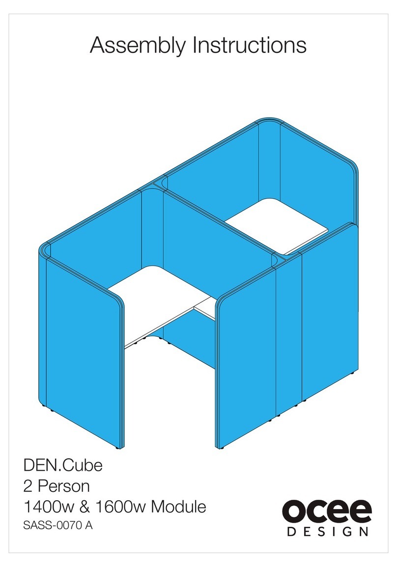
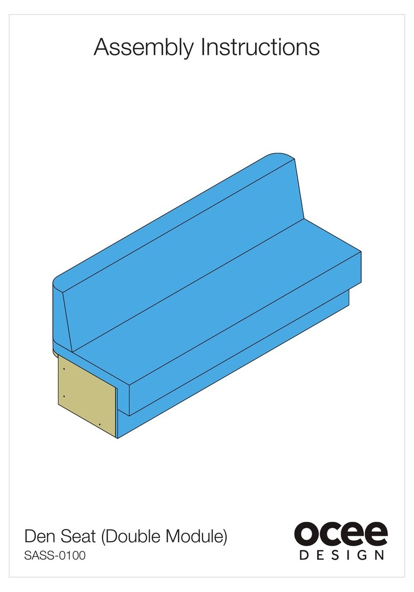
OCEE DESIGN Den Seat SASS-0079 A User manual

OCEE DESIGN

OCEE DESIGN Den Seat SASS-0079 A User manual

OCEE DESIGN SASS-0102 User manual

OCEE DESIGN

OCEE DESIGN SASS-0102 User manual

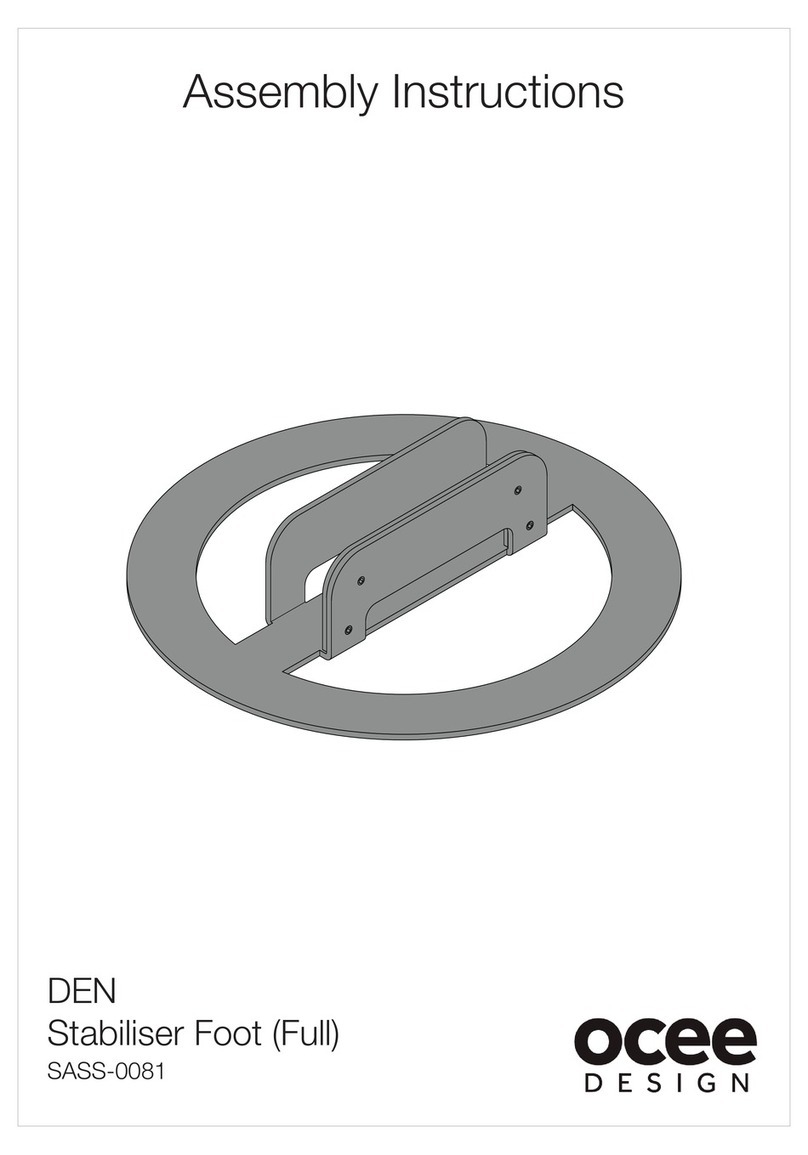
OCEE DESIGN DEN SASS-0081 User manual

OCEE DESIGN

OCEE DESIGN DEN SASS-0081 User manual

OCEE DESIGN DEN.Booth SASS-0040 B User manual

OCEE DESIGN

OCEE DESIGN DEN.Booth SASS-0040 B User manual

OCEE DESIGN SASS-0090 User manual

OCEE DESIGN

OCEE DESIGN SASS-0090 User manual

OCEE DESIGN DEN.Curve User manual

OCEE DESIGN

OCEE DESIGN DEN.Curve User manual

OCEE DESIGN DEN.Panel Triple SASS-0068 A User manual

OCEE DESIGN

OCEE DESIGN DEN.Panel Triple SASS-0068 A User manual

OCEE DESIGN DEN 675d Module User manual

OCEE DESIGN

OCEE DESIGN DEN 675d Module User manual

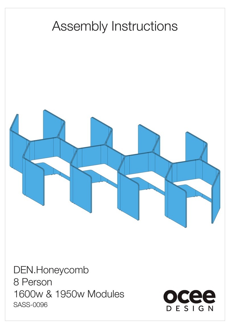
OCEE DESIGN SASS-0096 User manual

OCEE DESIGN

OCEE DESIGN SASS-0096 User manual

OCEE DESIGN DEN SASS-0082 User manual

OCEE DESIGN

OCEE DESIGN DEN SASS-0082 User manual

OCEE DESIGN SASS-0100 User manual

OCEE DESIGN

OCEE DESIGN SASS-0100 User manual

OCEE DESIGN DEN.Cube User manual

OCEE DESIGN

OCEE DESIGN DEN.Cube User manual

Popular Office Equipment manuals by other brands

LDI Safco 5350 Assembly instructions

LDI

LDI Safco 5350 Assembly instructions

SnapCab Meet 6 manual

SnapCab

SnapCab Meet 6 manual

Mo Systeme modulbox manual

Mo Systeme

Mo Systeme modulbox manual

Neopost IM 30 Operator's manual

Neopost

Neopost IM 30 Operator's manual

Casio EXILIM Exilim EX S 880 Catalog

Casio

Casio EXILIM Exilim EX S 880 Catalog

Panasonic Panafax UF-550 Service manual

Panasonic

Panasonic Panafax UF-550 Service manual

Woodworker's Hardware KV5710 quick start guide

Woodworker's Hardware

Woodworker's Hardware KV5710 quick start guide

Ergotron Anthro-DNA Steve's Station Essential Assembly instructions

Ergotron

Ergotron Anthro-DNA Steve's Station Essential Assembly instructions

Kodak X-Omat 270 RA PROCESSOR Service manual

Kodak

Kodak X-Omat 270 RA PROCESSOR Service manual

Phoenix FS2250 Series operating instructions

Phoenix

Phoenix FS2250 Series operating instructions

Lassco Wizer LASSCOJOG LJ-8 user manual

Lassco Wizer

Lassco Wizer LASSCOJOG LJ-8 user manual

Duplo DC-6 Mini Maintenance manual

Duplo

Duplo DC-6 Mini Maintenance manual

Kimball Definition Keyhole Top Assembly instructions

Kimball

Kimball Definition Keyhole Top Assembly instructions

Plustek OPTICFILM 7400 - brochure

Plustek

Plustek OPTICFILM 7400 - brochure

KI WireWorks Assembly instructions

KI

KI WireWorks Assembly instructions

Crestron SSW-100 installation guide

Crestron

Crestron SSW-100 installation guide

GRAPHTEC F-Mark Setup manual

GRAPHTEC

GRAPHTEC F-Mark Setup manual

Steelcase Avenir Panel manual

Steelcase

Steelcase Avenir Panel manual

manuals.online logo
manuals.online logoBrands
  • About & Mission
  • Contact us
  • Privacy Policy
  • Terms and Conditions

Copyright 2025 Manuals.Online. All Rights Reserved.