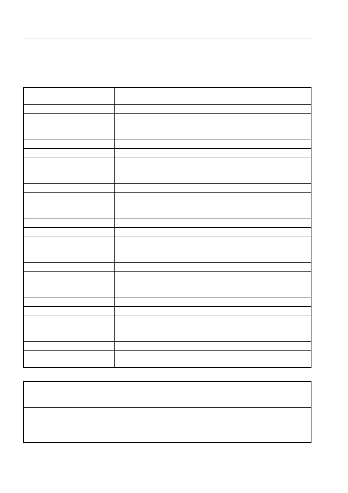
Plus M-5 User manual

COPY BOARD
M-5
SERVICE MANUAL

1. COMPLIANCE OF SAFE REPAIR ............................... 1
1-1. Cautions during Product Movement .......................... 1
1-2. Cautions during disassembling and assembling ........ 1
2.SPECIFICATIONS ......................................................... 2
2-1. Product Specifications ............................................... 2
2-2. Location of Main Set .................................................. 3
2-3. Control Panel of Main Unit, Location of Terminal ....... 4
2-4. Scanning area ............................................................ 5
2-5. Movements state indicators ....................................... 5
3.TROUBLE SHOOTING.................................................. 7
3-1. Trouble Shooting ........................................................ 7
3-2. Error Log List ............................................................. 8
4. DISASSEMBLY AND ASSEMBLY ............................... 9
4-1. Tools Required ........................................................... 9
4-2. Caution ...................................................................... 9
4-3. Disassembly and Assembly Procedures .................... 9
4-4. Disassembly and Assembly ....................................... 9
CONTENTS
5.ADJUSTMENT ............................................................... 10
5-1. CCD Unit Adjustment ................................................. 14
5-2. Calibration .................................................................. 20
5-3. Quick Calibration ....................................................... 22
5-4. Tension Adjustment of Timing Belt ............................. 23
6.CABLE AND CABLE CONNECTION ........................... 24
7.PARTS LIST .................................................................. 25
7-1. FRAME COVER SECTION........................................ 25
7-2. BOARD FRAME SECTION........................................ 27
7-3. SHEET FRAME SECTION ........................................ 28
7-4. ACCESSORIES SECTION ........................................ 29
7-5. CARTON PACKING SECTION .................................. 31
7-6. SCREWS AND WASHERS SECTION....................... 33
7-7. M-5-T (OS) ................................................................. 34
8.REVISION HISTORY ..................................................... 36

1
1. COMPLIANCE OF SAFE REPAIR
Be sure to read this Service Manual before providing services. In the PLUS Copyboard, full consideration is
taken to ensure the safety for a fire, electric shock, injury, harmful radiation, and substance. Therefore, observe
the notice described in this Service Manual so that the safety is kept when providing services. Moreover, be sure
to observe the notice described in the Instruction Manual.
Pay attention to the following during service inspection.
1-1. Cautions during Product Movement
• It is necessary to remove the products when making the service of products put on the wall. At that time, hold
the products by two or more persons to prevent the products from dropping or a person from falling down.
1-2. Cautions during disassembling and assembling
1. This equipment contains parts under high voltage. When doing repairs, make sure that power plug is pulled
out to insure safety.
2. Make sure that parts and screws and wiring, etc. are returned to their original positions. Tube, tape and
other insulation materials have been used for safety reasons. The internal wiring has been designed to
avoid direct contact with hot parts or parts under high voltage when using clamps or other tools.
3. The parts used in this device have special safety features such as flame-resistance and anti-voltage proper-
ties. When replacing parts, always use parts supplied from the factory.
4. After finishing operations make sure that all parts and wires have been returned to their original position and
that there has been no deterioration of the area around the location that was worked on.
5. Be sure to use an earth band (wrist band) during repair and inspection.

2
2. SPECIFICATIONS
MODEL NAME
Installation system
DIMENSIONS
Dimensions (Main set only)
Weight (Main set)
Panel Size
Copy Area
Number of Pages
BOARD Paglng
Drive system
Read system
Read resolution
Read time
Built-in memory
MEMORY External memory
Compatible FAT format
File Format
CONTROL PANEL
Buttons
Indicators
Interface
PC Connection Port
PC connection
Driver software
POWER SUPPLY
AC Power Adapter
ENVIRONMENTAL
Temperature
CONDITION
Humidity
THE OTHERS Grid Line
ACCESSORIES
2-1. Product Specifications
M-5
Wall type (Horizontally installed as standard.)
Option: Stand installed vertically and horizontally, and partition installed horizontally
W1175 ✕ H708 ✕ D93mm (not including protrusion)
12.5Kg
W1018 ✕ H625mm
W978 ✕ H578mm
2
One-way endless (Horizontal or vertical scroll)
Sheet movement type (Horizontal type: Left scroll, Vertical type: Upper scroll)
Optical system of monochromatic CCD sensor reduction
2.7 dots/mm (66 dpi or the equivalent)
Approximately 12 seconds
Internal flash memory, effective capacity: Approximately 1.8 MB
Compact flash card (CF card) TYPE I, ATYPE II *1
FAT12, 16, 32
TIFF Format (Pack bits Compressed)(A PNG format can be specified optionally.)
Power, Memory, Clear, Feed/Stop, Position
Power LED (Green), Memory LED (Orange)
Conforms to USB2.0 Full Speed 12Mbps
USB B Type
Personal computer in which a USB terminal is provided as standard
and in which Windows 98SE/Me/2000/XP is installed
Windows 98SE: Provides a dedicated driver.
(Windows Me/200/XP provides an OS standard driver.)
Input: AC100-240, 50/60Hz
Output: DC19V, 3.42A
Power consumption: about 40W
10°C ~ 35°C
30% ~ 85% (non-condensing)
34 ✕ 34mm
Marker (Red, Black), Eraser, AC power adapter, Power cord (3m), USB cable
(3m), Driver setup CD-ROM, Operation manual
*1: A CompactFlash Card is not included in the package.

3
SPECIFICATIONS
2-2. Location of Main Set
12
1
2
2
3
5
12
6
11
11
8,10
7,9
1. Copyboard
2. Sheet
3. Control panel (see page 20)
4. DC Input jack (see page 20)
5. USB connector (type B) (see page 20)
6. Screw holes for mounting the marker tray
7.
Screw holes for mounting the wall mount fittings
(for upper brackets)
8.
Screw holes for mounting the wall mount fittings
(for brackets)
9.
Screw holes for installing the stand horizontaly
(for upper brackets)
10.
Screw holes for installing the stand horizontaly
(for lower brackets)
11.
Screw holes for installing the stand vertically
(for upper brackets)
12.
Screw holes for installing the stand vertically
(for lower brackets)
FRONT AND TOP
BACK AND BOTTOM
The diagram shows the copyboard set with the front
side facing down.

4
SPECIFICATIONS
4
7
9
3
2
1
10
8
6
5
M-5
CF
MEMORY
FEED
/STOP
POWER
CLEAR
POSITION
M-5
CF
MEMORY
FEED
/STOP
POWER
CLEAR
POSITION
M-5
M-5
When set vertically
The connectors are located
on the bottom side of the
copyboard.
The connectors are
located on the left side
of the copyboard.
1 POWER button
Turns on and off the power.
2 POWER indicator (Green)
The Power lamp lights when the power is
turned on. It goes off when the power is
turned off. This lamp indicates an error or
the operation state when it blinks.
3 MEMORY button
The Memory button is used to save the figures
or characters, drawn on the sheet surface,
in memory.
4 MEMORY indicator (Amber)
The Memory lamp blinks while figures or
characters are saved in memory. It notifies
the error state according to the blinking speed.
5 FEED/STOP button
The Feed/Stop button is used to feed one
sheet surface automatically and stop it fo-
rcibly.
6 CLEAR button
The Clear button is used to delete all image
files of internal memory. (Press this button
for more than three seconds in this case.)
7 Card slot
The card slot is exclusively used for a CF
memory card.
8 POSITION button
(
Pinhole: The button exists
in
the inner part of a hole.)
The Position button is used for vertical and
horizontal switching of the image saved in
memory.
9 DC Power jack
Connect the DC side of an AC power adapter
to the DC input terminal. (Connect only the
AC power adapter exclusively used for this
set to this terminal.)
10 USB connector (Type B)
Connect the USB terminal to the USB terminal
(type A) of a personal computer.
2-3. Operation Panel of Main Unit, Location of Terminal

5
SPECIFICATIONS
2-4. Scanning area
2-5. Movements state indicators
M-5
23.5mm
23.5mm
20mm 20mm
978mm
578mm
Area not scannable
Effective scanning area
* The effective vertical scanning area is
with in the ruled lines.
Effective scanning area
Scanning is not possible on the edges of
sheet. Write or draw with in the effective
scanning area.
Notation in this manual
Blinking period
Low-speed blink Lights for 0.5 sec/Goes off for 0.5 sec.
High-speed blink Lights for 0.18 sec/Goes off for 0.18 sec.
Intermittent blink Lights for 0.25 sec/Goes off for 0.25 sec/Lights for 0.25 sec/Goes off for 1.25 sec.
Error blink
The Memory indicator (Amber) and Power indicator (green) alternately blink at high speed.
Blinking period of Power and Memory indicator and notation in this manual
LED display
State
Blinking period
Situation of occurrence
Error blink The internal Flash write of an image file fails. Continued During file storage
The CF write of an image file fails. 5 seconds During file storage
The whole erasure of internal Flash fails. Continued
When the Position key is pressed and during AC ON
An SRAM test fails. Continued During AC ON
An internal Flash format fails. Continued During AC ON and during non-Format detection
Abnormality is detected in the light quantity of CCFL OFF.
Continued When the Power key is pressed
The no-lighting of CCFL is detected. Continued When the Power key is pressed
The detection of a CCD output peak value fails. Continued When the Memory key is pressed
The internal flash write of scan data fails. Continued When SRAM capacity is full
The access to an Ini/inf file fails. Continued During scan start
The access to an Ini/inf file fails. 5 seconds During CCFL ON
The access to an Ini/inf file fails. 5 seconds During Feed start
CF configuration fails. 5 seconds During USB/CF insertion
The empty capacity check of CF fails. 5 seconds When the Memory key is pressed
The empty capacity check of internal Flash fails. Continued When the Memory key is pressed
An error occurs in calibration. Continued During calibration
The creation of an Ini file fails. Continued
During AC ON and during nonexistence/destruction of Ini file
The creation of an Inf file fails. Continued
During AC ON and during nonexistence/destruction of Inf file
The erasure of an image file in internal Flash fails. Continued When the Clear key is pressed
LED display
Go to next page.

6
SPECIFICATIONS
LED display
Power indicator
blinks at low speed
Memory indicator
blinks at low speed
Power indicator lights
Memory indicator
blinks intermittently
Power indicator lights
Memory indicator
blinks at high speed
Memory indicator
lights
Power indicator lights
Memory indicator
lights dimly
Power indicator lights
Power indicator goes off
Memory indicator goes off
State
During check of CCFL-ON light quantity.
JOB execution is terminated normally.
The whole erasure of internal Flash is termi-
nated normally.
During setting of installation in the horizontal
position.
The upgrading of firmware is terminated nor-
mally.
During scan/image file storage.
During period of stabilized CCFL light quan-
tity queue by quick calibration.
During period of stabilized CCFL light quan-
tity queue by quick calibration.
During setting of installation in the vertical
position.
During erasure/movement of image file in
internal Flash.
Insufficient empty capacity in internal Flash
and CF.
Media memory full detection.
The upgrading of firmware is terminated ab-
normally.
During calibration (except during stabilized
CCFL quantity period).
During upgrading of firmware (during flash
erasure and write of CPU).
Normal state (Power ON/standby state).
During upgrading of firmware (during expan-
sion of MOT file).
Power OFF state.
Blinking period
Until the quantity of
light is stabilized
Until the quantity of
light is stabilized
5 seconds
5 seconds
5 seconds
Continued
-
5 minutes
Till the specified time
5 seconds (The Power
lamp goes off.)
Till completion
Continued
Continued
Continued
Till completion
Till completion
-
Till completion
-
Situation of occurrence
When the Power key is pressed
When the Memory key is pressed
in the Standby state
When a JOB exists and during
CF insertion
When the Position key is pressed
and during AC ON
When the Position key is pressed
During upgrading
When the Memory key is pressed
During quick calibration
During calibration
When the Position key is pressed
When the Clear key is pressed
When the Memory key is pressed
During storage of image file
During upgrading
During calibration
During upgrading
-
During upgrading
-

7
By checking operations normal usage time, it is possible to carry out judgments on malfunction to a certain extent. Carry out the following
checks before disassembling the equipment.
1. Press the POWER button and turn on the power.
The Power Lamp blinks. The Power Lamp lights. (Is the power turned on?)
No •The AC Adapter is not connected.
•The Power Cable is not connected.
•The AC Adapter is defective.
•The power cable is disconnected.
•The Main Board Assy is defective.
Yes
Does the error display appear?
Yes The Power and Memory lamps alternately blink at high speed.
•The Main Board Assy is defective.
•The CCFL Unit is defective.
•The CF is defective.
•The CCD Unit is defective.
The Memory indicator blink at high speed and the Power lamp ON.
•The connector is disconnected.
Main Board Assy : CN4, 6
CCD Unit : CN1
CCFL Inverter Unit : CN1, 2
•The CCD harness is disconnected.
•The CCFL harness is disconnected.
•The Main Board Assy is defective.
•The CCD Unit is defective.
•The CCFL Unit is defective.
No
2. Press the FEED/STOP button.
Does the sheet operate normally?
No No operation sound or abnormal sound is generated.
•The connector is disconnected.
Main Board Assy : CN1
Connector between Sheet Motor Assy and Motor Harness
•The Sheet Motor Assy is defective.
•The Main Board Assy is defective.
Only the operation sound of the Sheet Motor Assy is generated.
•The Timing Belt is disconnected.
An abnormal sound is generated..
•The Sheet Motor Assy is defective.
•The Sheet Assy is attached to the plate surface.
•Out-of-adjustment of Timing Belt.
Yes
3. Press the MEMORY button.
Does the error display appear?
Yes The Power and Memory indicator alternately blink at high speed.
•The Main Board Assy is defective.
•The CF is defective.
•The CCD Unit is defective.
No
Does the Memory indicator blink intermittently? (The Power lamp lights.)
Yes The empty capacity of internal flash and CF is insufficient.
No
4. Confirm the read image.
Does abnormality (such as a dark line or character rubbing) exist?
Yes •Out-of-adjustment of CCD Unit.
•Dust adheres to the mirror of the CCFL Unit.
•The brightness adjustment of M-5 setup utility is too thick or thin.
•The written character is too thin.
•Markers other than black and red markers are used.
•The installation surface for a wall type is distorted.
•The joint of the Sheet Assy is dirty.
•The CCD Unit is defective.
•The CCFL Unit is defective.
No
Normal operation
3. TROUBLE SHOOTING
3-1. Trouble Shooting

8
TROUBLE SHOOTING
3-2. Error Log List
When an error occurs during normal processing, an “M5.ERR”file is created and the contents of an error are left based on
the additional write system. The “M5.ERR”file is created in CF during CF insertion. It is created in internal flash during CF
non-insertion.
The contents of log and the corresponding contents of an error are shown in the table below.
No Contents of log Contents of error
1 Initial Flash Erase Error The erasure of internal Flash fails during AC ON.
2 Initial SRAM Test Error An error occurs in R/W of SRAM during AC ON.
3 Initial Flash Format Error The format of internal Flash fails during AC ON.
4 CCFL Off Over Error The CCD output is too high just before CCFL lights.
5 Scan CCFL Can’t ON Error CCFL lights, but the CCD output is too low.
6 Scan Peak Detect Error The peak value of CCD output cannot be detected during scan start.
7 Image Buff Write Error The write of special compression data in a buffer fails during scan.
8 Image Buff Overflow Error
The amount of special compression data exceeded the capacity of a buffer during scan.
9 User Cal. Flash Access Error An ini/inf file cannot be accessed by simplified calibration.
10
User Cal. White Level Store Error
The White Level write in an inf file by simplified calibration fails.
11 Scan Start Flash Access Error An ini/inf file cannot be accessed during scan start.
12 CCFL ON Flash Access Error
An ini/inf file cannot be accessed during start of stabilized CCFL light quantity operation.
13 Feed Flash Access Error An ini/inf file cannot be accessed during feed start.
14 Conf. Load Flash Access Error An ini file cannot be loaded.
15 CF Write (Image) Error The write of image data in CF fails. (CF access error)
16 Flash Write (Image) Error The write of image data in flash fails. (Flash access error)
17 Position Set Conf. Load Error The loading of an ini file fails during position setting.
18 Position Set Conf. Scan Error The search of an ini file fails during position setting.
19 Position Set Write Cal. Error The write of an ini file fails during position setting.
20 USB_in CF Config Error The configuration execution of CF fails during USB insertion. (CF access)
21 CF_in CF Config Error The configuration execution of CF fails during CF insertion. (CF access)
22 CF_in JOB ck Error The JOB file check of CF fails during CF insertion.
23 CF Free Byte ck Error The empty capacity check of CF fails. (CF access)
24 Flash Free Byte ck Error The empty capacity check of Flash fails. (Flash access)
25 Ini_file_ck Write Cal. Error The write of a default ini file fails during AC ON.
26 Ini_file_ck Change Conf. Error The modified write of the illegal data in an ini file fails during AC ON.
27 Inf_file_ck Write Cal. Error The write of a default inf file fails during AC ON.
28 Inf_file_ck Change Conf. Error The modified write of the illegal data in an inf file fails during AC ON.
29 Image File Move Error The movement of image data from Flash to CF fails.
30 Image Move Flash Delete Error The image deletion of flash fails during movement of image data from Flash to CF.
31 Image Erase Flash Delete Error The image deletion of flash fails during erasure of the whole Flash image data.
The following parts may be defective when the error log described above is generated.
Defective parts Contents of error log (Nos.1 to 31 in the table above)
Main Board Assy 1, 2, 3, 4, 5, 6, 7, 9, 10, 11, 12, 13, 14, 15, 16, 17, 18, 19, 20, 21, 22, 23, 24, 25, 26, 27,
28, 29, 30, 31
CCD Unit 4, 5, 6
CF 15, 20, 21, 22, 23, 29
No part defects 8 (Adjustment patterns are excessively written in the plate surface. For example, the
patterns are written so that they were painted out black.)

9
4. DISASSEMBLY AND ASSEMBLY
4-1. Tools Required
•Phillips screwdriver No. 2
•Cutting pliers
•Electrostatic elimination wrist band
4-2.Caution
•See “1. Compliance of Safety Repair and Safety Inspection”before disassembling and assembling.
•Put on gloves so that you do not cut your hand at the sharp edge of a frame during disassembly and assem-
bly.
•See “6. Wiring Diagram”and “7. Parts List”for the parts name or wiring.
•The point especially requiring attention when handling parts or performing disassembly and assembly con-
tains a caution. Be sure to follow this caution.
4-3. Disassembly and Assembly Procedures
Frame Cap Side Frame R
Side Frame L Section
Mounting Button
CCFL Unit
Main Board Assy
Switch Box Unit
Back Panel CCD Unit
Sheet Frame Section
CCFL Inverter Unit
Sheet Motor Assy

10
DISASSEMBLY AND ASSEMBLY
2) Remove the Side Frame R. (See Figure 2.)
1. Loosen the screw shown in portion A of Figure 2.
(Tightening torque: 10.0kgfcm)
2. Remove the “S-1”screw shown in Figure 2 and
then remove the Side Frame R. (Tightening torque:
10.0kgfcm)
4-4.Disassembly and Assembly
The disassembly and assembly procedures described
here are one example. During actual operation, disas-
semble and assemble the required parts referring to
“4-3. Disassembly and Assembly Procedures”.
Fig. 1
Fig. 3
Fig. 2
Frame Cap A
Frame Cap C
Frame Cap C
Frame Cap B
Portion
A
Side Frame R
S-1
S-1
Back Panel
1) Remove the Frame Cap. (See Figure 1.)
1. Remove Frame Caps A, B, and C as shown in Fig-
ure 1.
Notes:
•Put the hooks of the Frame Caps in the main set as
shown in the expanded section of Figure 1 when
installing the Frame Caps.
•Double-sided adhesive tape is attached to the Frame
Caps.
3) Remove the Back Panel. (See Figure 3.)
1. Remove the Mounting Button shown in Figure 3.
2. Slide the Back Panel and remove it.

11
DISASSEMBLY AND ASSEMBLY
Fig. 6
Fig. 4
Fig. 5
4) Remove the Side Frame L Section. (See Figure 4.)
1. Remove the “S-1”screw shown in Figure 4.
(Tightening torque: 10.0kgfcm)
6) Remove the CCFL Unit. (See Figure 6.)
1. Disconnect the harness of the CCFL Unit from the
CCFL Inverter Unit.
2. Remove the “S-1”screw shown in Figure 6 and
then remove the Side Frame Plate. (Tightening
torque: 10.0kgfcm)
3. Remove the “S-5”screw shown in Figure 6 and
then remove the CCFL Unit. (Tightening torque:
4.5kgfcm)
Notes:
•Be careful not to damage the mirror surface of the
CCFL Unit.
Side Frame L Section
S-1
S-1
Main Board Cover A
Main Board Cover Unit
Main Board Assy
Hexagonal Spacer M3-5
Switch Sheet
Switch Box Unit
S-4
S-2
S-2
S-3
Side Frame Plate
Side Frame Plate
CCFL Unit
S-1
S-1
S-5
S-5
5) Remove the Main Board Assy and Switch Box Unit.
(See Figure 5.)
1. Remove Main Board Cover A shown in Figure 5.
2. Remove the “S-2”screw fixing the Main Board
Cover Unit and then remove the Main Board Cover
Unit.(Tightening torque: 4.5kgfcm)
3. Remove the “S-2”screw fixing the Main Board Assy
and then remove the Main Board Assy. (Tighten-
ing torque: 4.5kgfcm)
4. Remove the Switch Sheet.
5. Remove the “S-3”and “S-4”screws shown in Fig-
ure 5 and then remove the Switch Box Unit. (Tight-
ening torque: 4.5kgfcm)
Notes:
•Main Board Cover A is attached to the Main Board
Cover Unit. Main Board Cover A can be reused if
you can peel it well.
•The Switch Sheet cannot be reused. Therefore,
prepare a new one when removing the Switch Box
Unit.
2. Disconnect the harness connected to the Main
Board Assy.
3. Remove the Side Frame L Section.

12
DISASSEMBLY AND ASSEMBLY
Fig. 9
Fig. 8
Fig. 7
7) Remove the Sheet Frame Section.
(See Figures 7 and 8.)
1. Disconnect the Motor Harness from the Sheet Motor
Assy. (See Figure 8.)
2. Remove the “S-5”screw shown in Figure 7. (Tight-
ening torque: 4.5kgfcm)
3. Remove the “S-6”screw shown in Figure 7. (Tight-
ening torque: 10.0kgfcm)
4. Slide the Sheet Frame Section from the Board
Frame Section in the direction indicated by the ar-
row shown in Figure 7 and remove it.
Notes:
•Be careful not to damage the Sheet during installa-
tion and removal.
8) Remove the Sheet Motor Assy. (See Figure 8.)
1. Remove the “S-7”screw shown in Figure 8 and
then remove the Sheet Motor Assy. (Tightening
torque: 4.5kgfcm)
Notes:
•Be careful not to forget the Vibration Proof Rubber
during assembling.
9) Remove the Sheet Assy.
(See Figures 9, 10, and 11.)
1. Push the sheet roller section toward the inside as
shown in Figures 9 and 10.
2. Remove the Sheet Assy as shown in Figure 11.
Notes:
•Be careful not to do damage or make a fold when
handling the Sheet Assy.
Motor Harness
Sheet Motor Assy
Vibration Proof Rubber
S-7
Sheet Assy
Sheet Assy
Sheet Frame Section
Board Frame Section
S-6
S-6
S-5
Fig. 10 Fig. 11

13
DISASSEMBLY AND ASSEMBLY
Fig. 12
Fig. 13
10) Remove the CCD Unit. (See Figure 12.)
1. Disconnect the CCD Harness from the CCD Unit.
2. Remove the “S-7”screw shown in Figure 12 and
then remove the CCD Unit. (Tightening torque:
4.5kgfcm)
Notes:
•Adjustment is required when replacing and removing
the CCD Unit. (See 5. Adjustment method.)
11) Remove the CCFL Inverter Unit. (See Figure 13.)
1. Disconnect the CCFL Harness from the CCFL In-
verter Unit.
2. Remove the “S-8”screw shown in Figure 13 and
then remove the CCFL Inverter Unit. (Tightening
torque: 4.5kgfcm)
CCD Unit
CCD Harness
S-7
S-7
CCFL Inverter Unit
CCFL Harness
S-8

14
5. ADJUSTMENT
5-1. CCD Unit Adjustment
Adjustment is required in the following case. (Calibration is also required. See 5-2. Calibration method.)
•When a CCD Unit is replaced
•When adjustment gets out of order due to the failure during shipping (shock during transportation such as
vibration)
•Severest deterioration in picture quality (The picture quality may not be improved.)
Preparation
•Oscilloscope
•Phillips screwdriver No. 2
•Screwdriver for ceramic adjustment (2mm wide)
•Allen wrench (Across flat has 1.5 mm)
Turn ON the power to an oscilloscope. Clean the plate surface sufficiently.
* Insufficient cleaning may influence the subsequent calibration and cause sometimes irregular color.
CCD Unit adjustment procedure
1) Remove the Back Panel.
2) Connect an oscilloscope to the CCD Unit (CCD board).
(See the figure on the right.)
•Connect GND in Ch2 (Ext TRG) to J4.
•Connect the measurement pin in Ch2 to J3 (TRG).
•Connect GND in Ch1 to J1.
•Connect the measurement pin in Ch1 to J2.
3) Setting of oscilloscope
•Set the Ch1 mode to 2 V/DIV AC.
•Set the Ch2 (Ext TRG) mode to 1 V/DIV DC.
•Set the sweep to 500 Ésec/DIV.
•Set the trigger to EXT or Ch2.
•Only Ch1 is displayed.
J4
J3
J2
J1
VR
CCD Unit
CCD Unit

15
ADJUSTMENT
4) Focus adjustment screw of lens unit (See Figure 1.)
Fix screw A temporarily so that the distance between the lens unit and holder is 1.7 mm.
5) Write test patterns on the sheet surface. (See Figures 2 and 3.)
(Clean the plate surface sufficiently. If not, the subsequent calibration cannot be performed correctly.)
As shown in Figure 2, write test patterns on the plate surface using a black marker.
•Write horizontal lines of 68 mm (two ruled lines) in the upper, middle, and lower positions according to the
ruled line.
•Write vertical lines in the upper, middle, and lower positions, 68 mm (two ruled lines) away from the
horizontal lines, according to the ruled line.
(In only the middle position, the vertical line is 68 mm (two ruled lines). In the upper and lower positions,
the vertical lines are 34 mm (one ruled line).
Notes: Write them so that the horizontal lines in the upper and lower positions are put in the ruled lines as
shown in Figure 3.
E
1.7
Fig. 1
Fig. 2 Fig. 3

16
ADJUSTMENT
6) Put the set into the adjustment mode.
•Turn ON the power.
•Insert CF in which a command in the adjustment mode was put.
The set is put into the CCD adjustment mode, so confirm that CCFL lights.
7) Adjustment of oscilloscope (See Figures 4 and 5.)
•Adjust the trigger level, CH1 vertical position, Ch1 horizontal position, luminance, and focus so that a CCD
waveform appears on the oscilloscope. Also, adjust the trigger level in Ch2 (Ext TRG) and fix the wave-
form.
•Adjust VR on the CCD board so that the waveform is set to 4 Vp-p using a ceramic adjustment screwdriver.
Perform the adjustment described above.The adjustment is satisfactory if the waveform shown in Figure 4
or 5 appears.
4V 4V
Fig. 4 Fig. 5

17
ADJUSTMENT
8) Right and left swing adjustment of CCD Unit (See Figures 6 to 9.)
•As shown in Figures 6 and 7, insert a scale of 19 mm from the external and center positions of a CCFL unit.
•Loosen screw B shown in Figure 8, move sheet metal C, and fix screw B when the waveform falls to the
intermediate level as shown in Figure 9.
19
19
Sheet Roller
Sheet Assy
CCPL
Mirror
CCFL Unit
Reed Position
B
C
Fig. 8 Fig. 9
Fig. 6
Fig. 7

18
ADJUSTMENT
9) Torsion adjustment of CCD Unit (See Figures 10 and 11.)
•Move a sheet so that the test patterns (vertical lines) written in step 5) are displayed on an oscilloscope.
•Loosen screws D shown in Figure 10, move the CCD board, and fix screws D when the upper and lower
vertical lines equally go down as shown in Figure 11.
10) Focus adjustment (See Figures 12 and 13.)
•Loosen screw E shown in Figure 12, monitor the waveform on the oscilloscope displayed during adjust-
ment in step 9), and move the lens unit for focus adjustment so that the waveform becomes sharp as far as
possible.
•Fix screw E when the waveform becomes sharp as shown in Figure 13.
Notes: If the focus is insufficiently adjusted, an error may occur during calibration offset correction de-
scribed later.
D
3
Tek Run Trig'd
0
9 Jan 2004
11:34:54
E
Fig. 10
Fig. 11
Fig. 12
Fig. 13
Other manuals for M-5
3
Table of contents
Other Plus Office Equipment manuals
Popular Office Equipment manuals by other brands

Konica Minolta
Konica Minolta bizhub press c1060 Shortcut manual

Xerox
Xerox WORKCENTRE 7425 Quick use guide

OCEE DESIGN
OCEE DESIGN DEN.Panel Triple SASS-0068 A Assembly instructions

Steelcase
Steelcase Power Panel Supply System Assembly instructions

BuzziSpace
BuzziSpace BuzziNest Pod installation manual

Paitec
Paitec ES-2000 user manual