ENFORCER Stand-Alone / Wiegand Proximity Reader
SECO-LARM U.S.A., Inc. 3
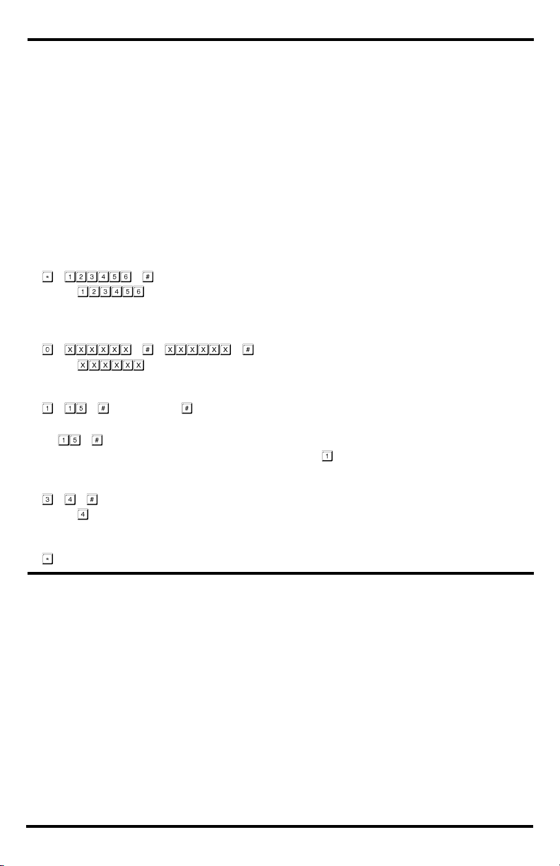
Quick Programming Guide:
Table of Contents:
All programming is done using the included infrared programmer or Master Add/Delete Cards.
Master programming code (6 digits) should be programmed before any other programming.
A steady red LED indicates that reader is powered on and ready. The LED will change to orange and a
single beep will sound to indicate the device has entered programming mode.
Programming Instructions:
Follow the instructions below if the following covers your needs:
A new master programming code
Setting a user card
A door-unlocked time of 4 seconds after the output is activated
Access mode / security level set to "single card" (default)
1. Enter base programming mode:
NOTE: is the factory default master programming code. A new master programming code
(6 digits) should be set the first time you enter programming mode.
2. Set the master programming code (6 digits):
NOTE: is the new master programming code and must be entered twice.
3. Set a user card to operate the output (unlock the door):
Read Card
NOTES:
chooses user ID #15 of 998 possible user IDs (0~997).
To add other users do not repeat the initial function code .
4. Set the output time (skip this step if the default value of 5 seconds is acceptable):
NOTE: sets the output delay time for 4 seconds.
5. Exit programming mode:
One short beep will sound to indicated that the reader has exited programming mode.
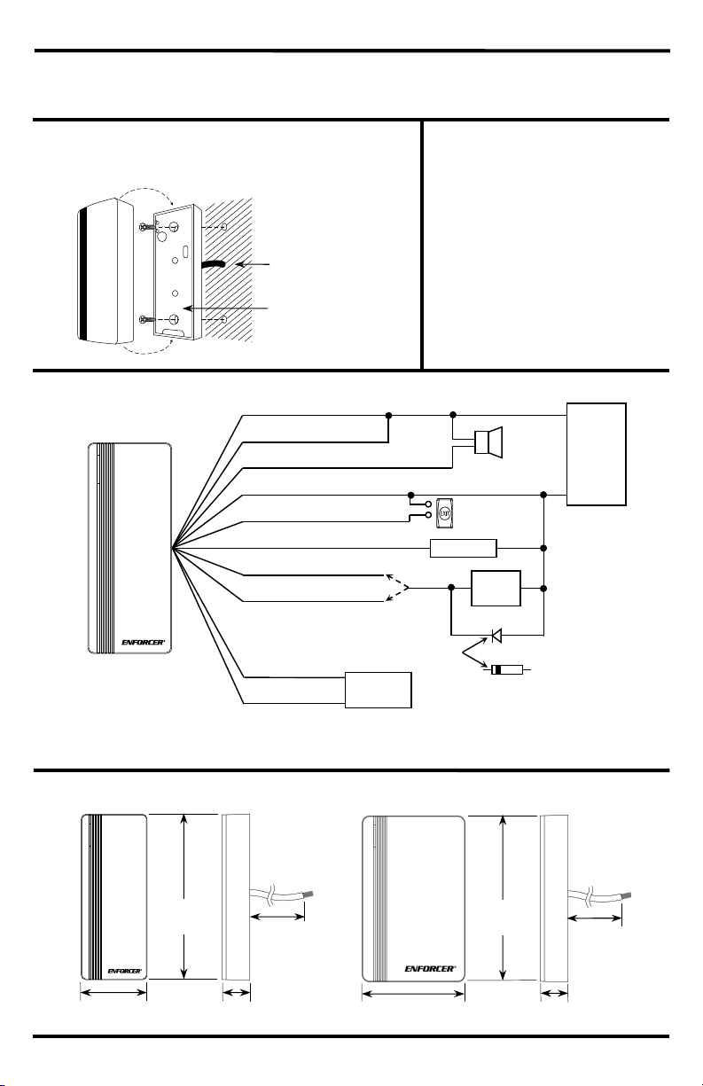
Quick Installation Guide: .................................................... 2
Mounting Diagram: ............................................................ 2
Parts List: ........................................................................... 2
Quick Wiring Diagram: ....................................................... 2
Overview: ........................................................................... 2
Quick Programming Guide: ............................................... 3
Table of Contents: ............................................................. 3
Specifications: .................................................................... 4
Important Notes: ................................................................ 4
LED Indicators and Device Sounds: .................................. 4
Wiring Chart: ...................................................................... 5
Installation: ......................................................................... 5
Getting Ready to Program: ............................................ 5~6
Programming Format and Default Values: .................... 6~7
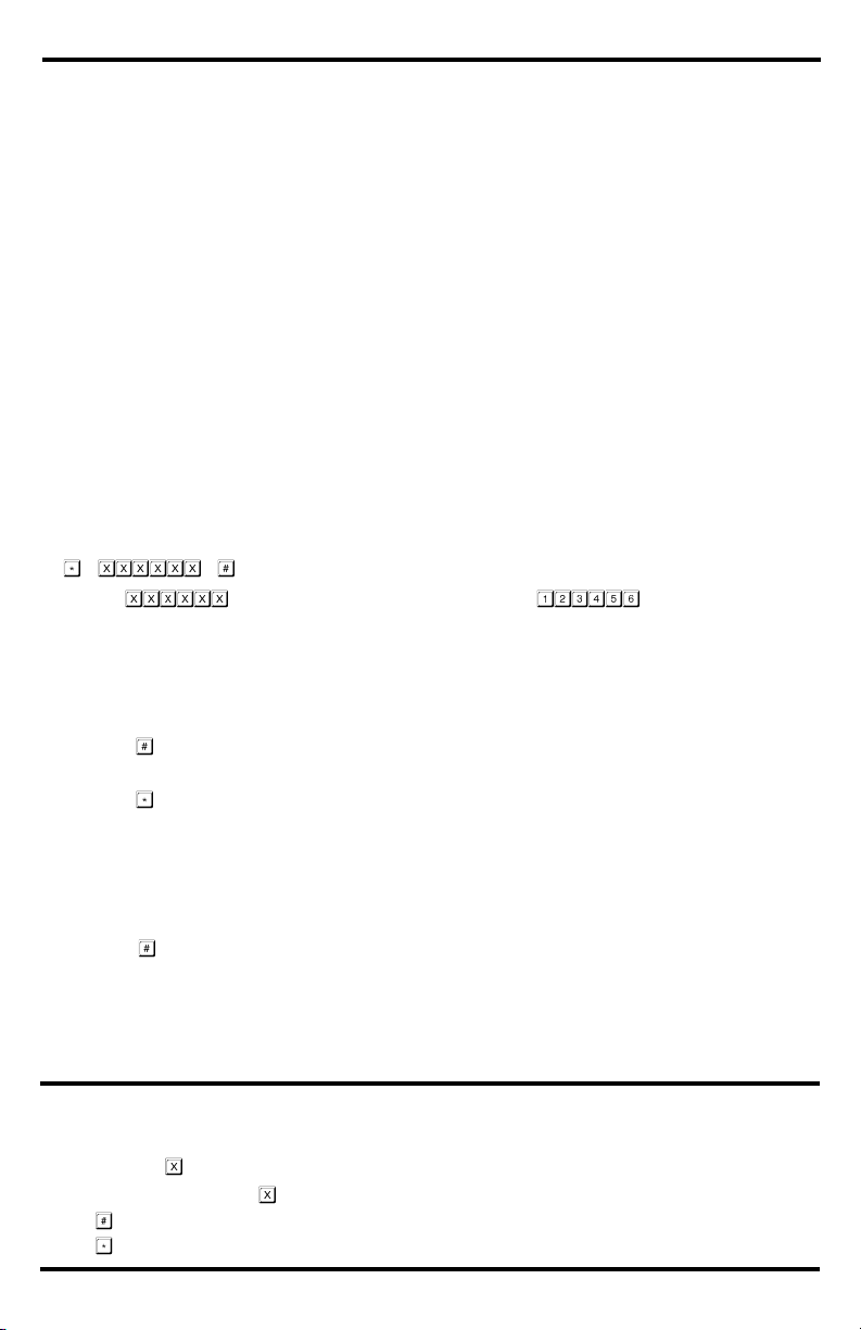
Programming the Master Programming Code:.................. 7
Setting the Reader Operation Mode: ................................. 7
Programming the Access Mode / Security Level: ......... 7~8
Programming User Proximity Cards:..............................8~9
Programming Duress Cards: .............................................. 9
Deleting Users: ................................................................. 10
Programming Output Mode and Time: ...................... 10~11
Programming Notification Sounds and LED: ................... 11
Programming the External Alarm Output: ................. 11~12
Programming the Wrong-Card Lockout/Alarm: ......... 12~13
User Operation of the Reader .......................................... 13
Setting up a Two-Door Interlock System: ................. 13~14
Wiegand Controller Mode:......................................... 14~15
Wiegand Reader Mode: ................................................... 15
Duplicating Users to Other Reader: ................................. 15
Resetting to Factory Default and Programming
Add/Delete Cards: ...................................................... 16
Troubleshooting: ............................................................... 16
Additional Accessories from SECO-LARM: ..................... 16
Warranty: .......................................................................... 16