Seco SBC-A62-J User manual

SBC-A62-J
Single Board Computer
with NXP i.MX6 Processor
SBC-A62-J
SBC-A62-J User Manual - Rev. First Edition: 1.0 - Last Edition: 2.3 - Author: S.B. - Reviewed by N.P. Copyright © 2016 SECO S.r.l.
2
All rights reserved. All information contained in this manual is proprietary and confidential material of SECO S.r.l.
Unauthorized use, duplication, modification or disclosure of the information to a third-party by any means without prior consent of SECO S.r.l. is prohibited.
Every effort has been made to ensure the accuracy of this manual. However, SECO S.r.l. accepts no responsibility for any inaccuracies, errors or omissions herein.
SECO S.r.l. reserves the right to change precise specifications without prior notice to supply the best product possible.
For further information on this module or other SECO products, but also to get the required assistance for any and possible issues, please contact us using the
dedicated web form available at http://www.seco.com (registration required).
Our team is ready to assist.
Revision
Date
Note
Ref
1.0
18th May 2015
First Official Release.
SB
1.1
11th June 2015
J29 connector pinout corrected
SB
1.2
9th September 2015
J27 jumper description added. Minor corrections.
SB
2.0
17th February 2016
Product name change. Power rail names updated.
SB
2.1
28th July 2016
description updated.
SB
2.2
10th May 2017
Specifications updated (i.MX6Dual Plus added)
Typo corrected in paragraph 3.3.17
SB
2.3
4th August 2017
Typo corrected in paragraph 3.3.2 (wrong mating connector s part number)
SB
REVISION HISTORY

SBC-A62-J
SBC-A62-J User Manual - Rev. First Edition: 1.0 - Last Edition: 2.3 - Author: S.B. - Reviewed by N.P. Copyright © 2016 SECO S.r.l.
3
INDEX
INTRODUCTION.......................................................................................................................................................................... 5Chapter 1.
1.1 Warranty........................................................................................................................................................................................................................................ 6
1.2 Information and assistance............................................................................................................................................................................................................. 7
1.3 RMA number request..................................................................................................................................................................................................................... 7
1.4 Safety............................................................................................................................................................................................................................................ 8
1.5 Electrostatic discharges ................................................................................................................................................................................................................. 8
1.6 RoHS compliance.......................................................................................................................................................................................................................... 8
1.7 Terminology and definitions ............................................................................................................................................................................................................9
1.8 Reference specifications ..............................................................................................................................................................................................................11
OVERVIEW ............................................................................................................................................................................... 12Chapter 2.
2.1 Introduction..................................................................................................................................................................................................................................13
2.2 Technical specifications ...............................................................................................................................................................................................................14
2.3 Electrical specifications ................................................................................................................................................................................................................15
2.3.1 RTC Battery.........................................................................................................................................................................................................................15
2.3.2 Power rails...........................................................................................................................................................................................................................16
2.4 Mechanical specifications............................................................................................................................................................................................................. 17
2.5 Block diagram..............................................................................................................................................................................................................................18
CONNECTORS......................................................................................................................................................................... 19Chapter 3.
3.1 Introduction..................................................................................................................................................................................................................................20
3.2 Connectors overview ...................................................................................................................................................................................................................21
3.3 Connectors description................................................................................................................................................................................................................22
3.3.1 LVDS + backlight connector................................................................................................................................................................................................. 22
3.3.2 I2C Touch Screen Connector...............................................................................................................................................................................................23
3.3.3 Optional HDMI connector.....................................................................................................................................................................................................24
3.3.4 Optional Camera connector .................................................................................................................................................................................................25
3.3.5 Ethernet connector ..............................................................................................................................................................................................................26
3.3.6 USB ports............................................................................................................................................................................................................................27
3.3.7 S-ATA connectors (i.MX6DP and i.MX6Q versions only)........................................................................................................................................................28
3.3.8 μSD card slot ......................................................................................................................................................................................................................29
3.3.9 Optional Audio Jacks ...........................................................................................................................................................................................................30

SBC-A62-J
SBC-A62-J User Manual - Rev. First Edition: 1.0 - Last Edition: 2.3 - Author: S.B. - Reviewed by N.P. Copyright © 2016 SECO S.r.l.
4
3.3.10 CAN Bus connector.............................................................................................................................................................................................................30
3.3.11 Optional FAN/GPIO connector..............................................................................................................................................................................................30
3.3.12 Recovery jumper JP1...........................................................................................................................................................................................................31
3.3.13 Boot Selection jumper J27...................................................................................................................................................................................................31
3.3.14 Power and Reset buttons.....................................................................................................................................................................................................31
3.3.15 Expansion connector ...........................................................................................................................................................................................................32
3.3.16 Optional JTAG connector.....................................................................................................................................................................................................34
3.3.17 Debug UART connector....................................................................................................................................................................................................... 34
APPENDICES............................................................................................................................................................................ 35Chapter 4.
4.1 Thermal Design............................................................................................................................................................................................................................36
4.2 Accessories.................................................................................................................................................................................................................................37
4.2.1 RS-232 programming kit......................................................................................................................................................................................................37
4.2.2 WiFi Modules.......................................................................................................................................................................................................................37
4.2.3 Cabled RTC battery. ............................................................................................................................................................................................................38
4.2.4 CSI Dongle Camera VA09....................................................................................................................................................................................................38

SBC-A62-J
SBC-A62-J User Manual - Rev. First Edition: 1.0 - Last Edition: 2.3 - Author: S.B. - Reviewed by N.P. Copyright © 2016 SECO S.r.l.
5
Chapter 1.
Warranty
Information and assistance
RMA number request
Safety
Electrostatic discharges
RoHS compliance
Terminology and definitions
Reference specifications

SBC-A62-J
SBC-A62-J User Manual - Rev. First Edition: 1.0 - Last Edition: 2.3 - Author: S.B. - Reviewed by N.P. Copyright © 2016 SECO S.r.l.
6
1.1Warranty
This product is subject to the Italian Law Decree 24/2002, acting European Directive 1999/44/CE on matters of sale and warranties to consumers.
The warranty on this product lasts for 1 year.
Under the warranty period, the Supplier guarantees the buyer assistance and service for repairing, replacing or credit of the item, at the Supplier’s own discretion.
Shipping costs that apply to non-conforming items or items that need replacement are to be paid by the customer.
Items cannot be returned unless previously authorized by the supplier.
The authorization is released after completing the specific form available on the web-site http://www.seco.com/en/prerma (RMA Online). The RMA authorization
number must be put both on the packaging and on the documents shipped with the items, which must include all the accessories in their original packaging, with
no signs of damage to, or tampering with, any returned item.
The error analysis form identifying the fault type must be completed by the customer and has must accompany the returned item.
If any of the above mentioned requirements for RMA is not satisfied, the item will be shipped back and the customer will have to pay any and all shipping costs.
Following a technical analysis, the supplier will verify if all the requirements, for which a warranty service applies, are met. If the warranty cannot be applied, the
Supplier will calculate the minimum cost of this initial analysis on the item and the repair costs. Costs for replaced components will be calculated separately.
Warning!
All changes or modifications to the equipment not explicitly approved by SECO S.r.l. could impair the equipment’
s functionalities and could void
the warranty

SBC-A62-J
SBC-A62-J User Manual - Rev. First Edition: 1.0 - Last Edition: 2.3 - Author: S.B. - Reviewed by N.P. Copyright © 2016 SECO S.r.l.
7
1.2Information and assistance
What do I have to do if the product is faulty?
SECO S.r.l. offers the following services:
SECO website: visit http://www.seco.com to receive the latest information on the product. In most of the cases it is possible to find useful information to
solve the problem.
SECO Sales Representative: the Sales Rep can help to determine the exact cause of the problem and search for the best solution.
SECO Help-Desk: contact SECO Technical Assistance. A technician is at disposal to understand the exact origin of the problem and suggest the correct
solution. E-mail: technical.servic[email protected]
Fax (+39) 0575 340434
Repair center: it is possible to send the faulty product to the SECO Repair Centre. In this case, follow this procedure:
oReturned items must be accompanied by a RMA Number. Items sent without the RMA number will be not accepted.
oReturned items must be shipped in an appropriate package. SECO is not responsible for damages caused by accidental drop, improper usage, or
customer neglect.
Note: Please have the following information before asking for technical assistance:
Name and serial number of the product;
Description of Customer’s peripheral connections;
Description of Customer’s software (operative system, version, application software, etc.);
A complete description of the problem;
The exact words of every kind of error message encountered.
1.3RMA number request
To request a RMA number, please visit SECO’s web-site. On the home page, please select “RMA Online”and follow the procedure described.
A RMA Number will be sent within 1 working day (only for on-line RMA requests).

SBC-A62-J
SBC-A62-J User Manual - Rev. First Edition: 1.0 - Last Edition: 2.3 - Author: S.B. - Reviewed by N.P. Copyright © 2016 SECO S.r.l.
8
Whenever handling a SBC-A62-J board, ground yourself through an anti-static wrist strap. Placement of the board on an anti-static
surface is also highly recommended.
1.4Safety
The SBC-A62-J board uses only extremely-low voltages.
While handling the board, please use extreme caution to avoid any kind of risk or damages to electronic components.
1.5 Electrostatic discharges
The SBC-A62-J board, like any other electronic product, is an electrostatic sensitive device: high voltages caused by static electricity could damage some or all
the devices and/or components on-board.
1.6 RoHS compliance
The SBC-A62-J board is designed using RoHS compliant components and is manufactured on a lead-free production line. It is therefore fully RoHS compliant.
Always switch the power off, and unplug the power supply unit, before handling the board and/or connecting cables or other
boards.
Avoid using metallic components - like paper clips, screws and similar - near the board when connected to a power supply, to avoid
short circuits due to unwanted contacts with other board components.
If the board has become wet, never connect it to any external power supply unit or battery.
Check carefully that all cables are correctly connected and that they are not damaged.

SBC-A62-J
SBC-A62-J User Manual - Rev. First Edition: 1.0 - Last Edition: 2.3 - Author: S.B. - Reviewed by N.P. Copyright © 2016 SECO S.r.l.
9
1.7 Terminology and definitions
AC’97 Audio Codec’97, a standard for audio hardware codecs developed by Intel®in 1997
AHCI Advanced Host Controller Interface, a standard which defines the operation modes of SATA interface
API Application Program Interface, a set of commands and functions that can be used by programmers for writing software for specific Operating
Systems
CAN Bus Controller Area network, a protocol designed for in-vehicle communication
CEC Consumer Electronics Control, an HDMI feature which allows controlling more devices connected together by using only one remote control
CSI2 MIPI Camera Serial Interface, 2nd generation standard regulating communication between a peripheral device (camera) and a host processor
DDC Display Data Channel, a kind of I2C interface for digital communication between displays and graphics processing units (GPU)
DDR Double Data Rate, a typology of memory devices which transfer data both on the rising and on the falling edge of the clock
DDR3 DDR, 3rd generation
FFC/FPC Flexible Flat Cable / Flat Panel Cable
GBE Gigabit Ethernet
Gbps Gigabits per second
GND Ground
GPI/O General purpose Input/Output
HDMI High Definition Multimedia Interface, a digital audio and video interface
I2C Bus Inter-Integrated Circuit Bus, a simple serial bus consisting only of data and clock line, with multi-master capability
LVDS Low Voltage Differential Signaling, a standard for transferring data at very high speed using inexpensive twisted pairs copper cables, usually used
for video applications
MAC Medium Access Controller, the hardware implementing the Data Link Layer of ISO/OSI-7 model for communication systems
Mbps Megabits per second
MIPI Mobile Industry Processor Interface Alliance
MMC/eMMC MultiMedia Card / embedded MMC, a type of memory card, having the same interface of SD. The eMMC are the embedded version of the
MMC. They are devices that incorporate both the memory controller and the flash memories on a single BGA chip
N.A. Not Applicable
N.C. Not Connected
OpenCL Open Computing Language, a software library based on C99 programming language, conceived explicitly to realise parallel computing using
Graphics Processing Units (GPU)

SBC-A62-J
SBC-A62-J User Manual - Rev. First Edition: 1.0 - Last Edition: 2.3 - Author: S.B. - Reviewed by N.P. Copyright © 2016 SECO S.r.l.
10
OpenGL Open Graphics Library, an Open Source API dedicated to 2D and 3D graphics
OpenVG Open Vector Graphics, an Open Source API dedicated to hardware accelerated 2D vector graphics
OS Operating System
OTG On-the-Go, a specification that allows to USB devices to act indifferently as Host or as a Client, depending on the device connected to the port
PHY Abbreviation of Physical, it is the device implementing the Physical Layer of ISO/OSI-7 model for communication systems
PSU Power Supply Unit
PWM Pulse Width Modulation
PWR Power
RGMII Reduced Gigabit Media Independent Interface, a particular interface defining the communication between an Ethernet MAC and a PHY
SATA Serial Advance Technology Attachment, a differential half duplex serial interface for Hard Disks
SD Secure Digital, a memory card type
SM Bus System Management Bus, a subset of the I2C bus dedicated to communication with devices for system management, like a smart battery and
other power supply-related devices
SPI Serial Peripheral Interface, a 4-Wire synchronous full-duplex serial interface which contemplates a master and one or more slaves, individually
enabled through a Chip Select line
TBM To be measured
TMDS Transition-Minimized Differential Signaling, a method for transmitting high speed serial data, normally used on DVI and HDMI interfaces
TTL Transistor-transistor Logic
USB Universal Serial Bus
uSDHC Ultra Secure Digital Host Controller
V_REF Voltage reference Pin
SBC-A62-J
SBC-A62-J User Manual - Rev. First Edition: 1.0 - Last Edition: 2.3 - Author: S.B. - Reviewed by N.P. Copyright © 2016 SECO S.r.l.
11
1.8 Reference specifications
Here below it is a list of applicable industry specifications and reference documents.
Reference
Link
AC’97
http://download.intel.com/support/motherboards/desktop/sb/ac97_r23.pdf
AHCI
http://www.intel.com/content/www/us/en/io/serial-ata/ahci.html
CAN Bus
http://www.bosch-semiconductors.de/en/ubk_semiconductors/safe/ip_modules/can_literature/can_literature.html
CSI
http://www.mipi.org/specifications/camera-interface
Gigabit Ethernet
http://standards.ieee.org/about/get/802/802.3.html
HDMI
http://www.hdmi.org/index.aspx
I2C
http://www.nxp.com/documents/other/UM10204_v5.pdf
LVDS
http://www.ti.com/ww/en/analog/interface/lvds.shtml
http://www.ti.com/lit/ml/snla187/snla187.pdf
MIPI
http://www.mipi.org
MMC/eMMC
http://www.jedec.org/committees/jc-649
OpenCL
http://www.khronos.org/opencl
OpenGL
http://www.opengl.org
OpenVG
http://www.khronos.org/openvg
SATA
https://www.sata-io.org
SD Card Association
https://www.sdcard.org/home
SM Bus
http://www.smbus.org/specs
TMDS
http://www.siliconimage.com/technologies/tmds
USB 2.0 and USB OTG
http://www.usb.org/developers/docs/usb_20_070113.zip
NXP i.MX6 processor
http://www.nxp.com/products/microcontrollers-and-processors/arm-processors/i.mx-applications-processors-based-on-arm-
cores/i.mx-6-processors:IMX6X_SERIES?cof=0&am=0


SBC-A62-J
SBC-A62-J User Manual - Rev. First Edition: 1.0 - Last Edition: 2.3 - Author: S.B. - Reviewed by N.P. Copyright © 2016 SECO S.r.l.
13
2.1Introduction
SBC-A62-J is a Single Board Computer, measuring just 110 x 86.5 mm (4.5”x 3.7”) based on embedded NXP i.MX6 processors, an ARM®Cortex®-A9
processor, Single-, Dual- and Quad-Core, with frequencies up to 1GHz, which is ideal for applications requiring multimedia capabilities and/or high levels of parallel
computing maintaining advantages offered by low-power consuming ARM architecture in an extremely reduced space.
Graphics features of the board are managed directly by NXP i.MX6 processors, which integrate up to three separated accelerators for 2D, OpenGL®ES2.0 3D
and OpenVG , giving the processor incredible graphical performances (OpenVG accelerator is not available with i.MX6 Solo and Dual Lite processors).
The board is able to support up to 3 independent displays (with i.MX6DP Dual Core and i.MX6Q Quad core processor), which can be driven through the HDMI
connector and/or the LVDS connector. LVDS interface is also able to drive one 18/24 bit Single / Dual Channel display as well as two independent 18/24 bit
Single Channel displays. Using i.MX6 Dual Lite and Solo processors, support is limited to 2 independent displays.
The board is completed with up to 1GB DDR3L (up to 512MB with i.MX6 Solo) directly soldered on board, and one eMMC Flash Disk, directly accessible like any
standard Hard Disk, with up to 16GB of capacity. Mass storage capabilities are completed by the SATA connector (with i.MX6DP and i.MX6Q processors only),
which can be used to connect any external SATA disk, and a microSD Card slot.
RGMII i.MX6 native interface is internally carried to a Micrel KSZ9031RN Ethernet Transceiver, allowing the implementation of a Gigabit Ethernet interface.
USB native port is carried to an USB2.0 USB Hub controller, which allows implementing two standard USB 2-0 Type A ports, an internal USB port on dedicated
connector, and another USB port on a 6-pin or 7-pin female header, intended for the connection of optional WiFi modules.
The i.MX6 OTG port, instead, is carried to a USB micro-B connector, thus supporting the client mode only functionality.
An embedded AC’97 Audio Codec, then, manages two audio jacks for LineOut and Mic in.
The standard functionalities of this board are then completed by a 32-pin expansion connector, which carries out directly 28 signals coming from the i.MX6
processor. These signals can all be used as Generic Purpose Input/Outputs (GPIOs). Due to the pin multiplexing possibilities offered by the i.MX6 processor,
however, it is possible to use some groups of these pins to implement other functionalities, like 3 x UARTs (which can also be offered with RS-232 or RS-485
interface), SPI, 2 x CAN interfaces and more.
It is possible to have the board in EXTREME version, where all the components mounted onboard are certified to work in industrial range, therefore the board is
specifically developed to work in range -40°C ÷ +85°C..
Please refer to following chapter for a complete list of all peripherals integrated and characteristics. Not all combinations of these features are offered
simultaneously; please visit SECO’s website for a description of standard configuration modules offered. Configurations different from the standard offered must be
evaluated singularly; please contact a SECO’s sales representative / distributor for this.

2.2 Technical specifications
Processors
NXP i.MX6 Family, based on ARM®CORTEX-A9 processors
-i.MX6S Solo - Single core up to 1GHz
-i.MX6DL Dual Lite - Dual core up to 1GHz per core
-i.MX6DP Dual Plus - Dual core up to 1GHz per core
-i.MX6Q Quad - Quad core up to 1GHz per core
Memory
Soldered down DDR3L memory
i.MX6DP: 2GB 64-bit interface
i.MX6Q, i.MX6DL: 1GB 64-bit interface
i.MX6S: up to 512MB 32-bit
Graphics
Dedicated 2D Hardware accelerator
Dedicated 3D Hardware accelerator, supports OpenGL®ES2.0 3D
Dedicated Vector Graphics accelerator, supports OpenVG™(only i.MX6DP and
i.MX6Q)
Supports up to 3 independent displays with i.MX6DP and i.MX6Q
Supports 2 independent displays with i.MX6DL and i.MX6S
Video Interfaces
1 x LVDS Dual Channel or 2 x LVDS Single Channel 18/24 bit interface
HDMI Interface
MIPI-CSI Camera connector
Video Resolution
LVDS, up to 1920x1200
HDMI, resolution up to 1080p
Mass Storage
Optional on-board eMMC Disk, up to 16GB *
SATA connector (only i.MX6DP and i.MX6Q)
microSD card slot
SPI Flash soldered onboard
* Please consider that for HDD and Flash Disk manufacturers, 1GB = 10^9 Byte.
Some OS (like, for example, Windows) intends 1GB = 1024^3 byte, so global
capacity shown for Disk Properties will be less than expected. Please also consider
that a portion of disk capacity will be used by internal Flash Controller for Disk
management, so final capacity will be lower
Networking
Gigabit Ethernet connector
USB
2 x standard USB 2.0 Type A
Internal USB 2.0 connector
1 x USB micro-B client connector
Audio
AC’97 Audio Codec Realtek ALC655
Mic In, Line out Audio jacks
Serial Ports
Optional CAN Bus connector
Other interfaces
I2C touch Connector
32-pin expansion connector, configurable to offer:
Up to 28 GPIO
SPI interface
SPDIF Audio interface
2 x CAN interface (TTL level)
SDIO interface
3 x PWM
2 x I2C
3 x UARTs (TTL, RS-232, RS-485 modes)
Debug UART on dedicated connector
Power and reset buttons
Power supply voltage: +12VDC ± 10%
Embedded additional RTC circuitry for lowest power consumption
Operating temperature: 0°C ÷ +60°C** (commercial version)
-40°C ÷ +85°C** (industrial version)
Dimensions: 110 x 86.5 mm (4.5”x 3.7”).
Supported Operating Systems:
Linux
Android
** is to be considered at any point of the heatspreader/heatsink. Actual
temperature will widely depend on application, enclosure and/or
environment. p to the customer to consider specific cooling solutions
for the final system.
Please also check paragraph 4.1
CAUTION: handling batteries incorrectly or replacing with not-approved devices may present a risk of fire or explosion.
2.3Electrical specifications
SBC-A62-J needs to be supplied only with an external 12VDC ± 10% power supply, with a minimal 35W power rating.
This voltage can be supplied through an optional standard 6.3mm (internal pin, diameter 2.0 mm) Power Jack. Internal pin is VIN power line.
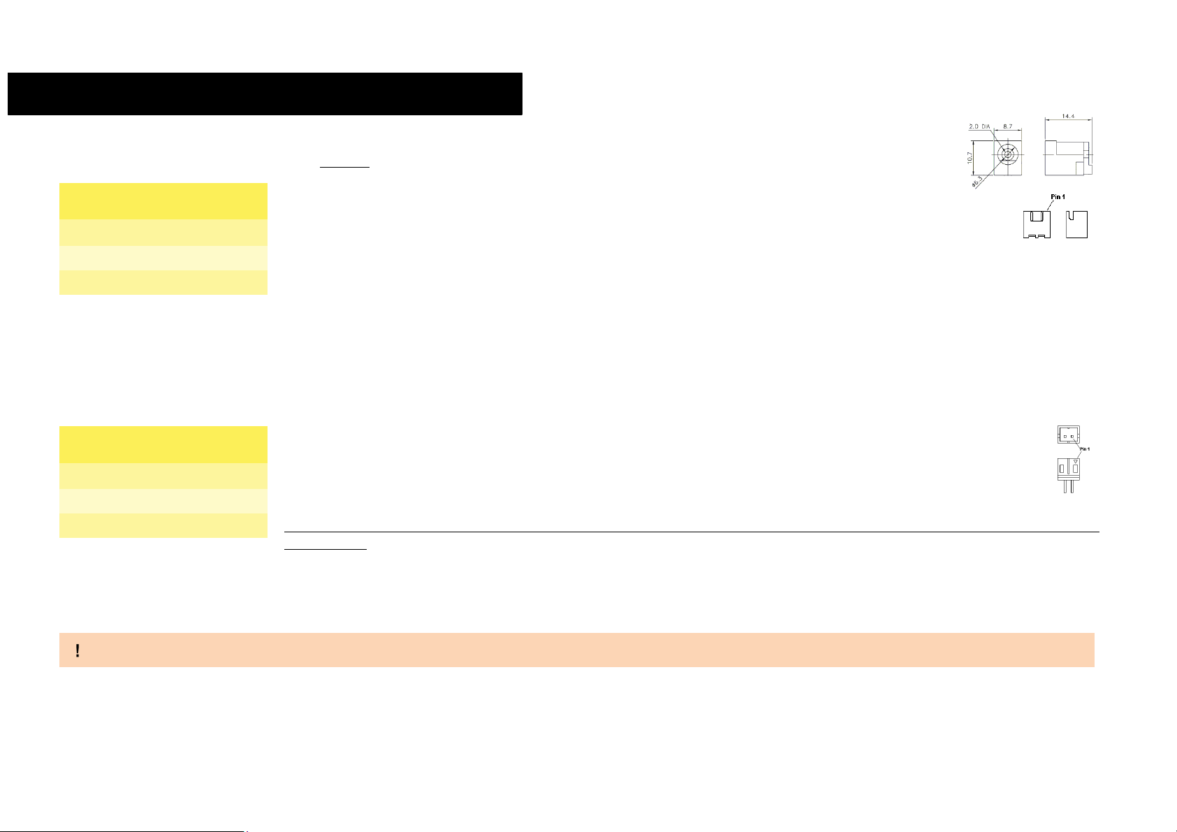
As an alternative, +12VDC can also be supplied using dedicated internal connector J26, which is a JST
XH series connector or equivalent, p/n B2B-XH-A(LF)(SN), 3A max current per contact, with pinout shown in the
table on the left.
Mating connector: JST XHP-2 receptacle with JST SXH-001T-P0.6 series of female crimp terminals.
2.3.1 RTC Battery
The SBC-A62-J board can be equipped with an optional low-power Real Time Clock embedded on the module (which is a NXP PCF2123). In this case, the board
also mounts a soldered horizontal 3V coin cell lithium battery to supply such a RTC.
The battery used is a not-rechargeable Panasonic BR-1225HCN Lithium coin-cell battery, with a nominal capacity of 48mAh.
As a factory alternative, it is possible to connect external cabled RTC batteries to supply the RTC clock embedded on the i.MX6 processor.
The battery used for this purpose must be not rechargeable, and can be connected to the board using dedicated
connector, J1, which is a 2-pin p1.27 mm type MOLEX p/n 89400-0220 or equivalent, with pinout shown in the table
on the left.
Mating connector: MOLEX 87369-0200 receptacle with MOLEX 50212-8000 female crimp terminals.
Please be aware that such a connector is optional, it will be present only in case that there isn’t the additional low-power
external RTC
In case of exhaustion, the battery should only be replaced with devices of the same type. Always check the orientation before inserting and make sure that they are
aligned correctly and are not damaged or leaking.
Never allow the batteries to become short-circuited during handling.
Batteries supplied with SBC-A62-J are compliant to requirements of European Directive 2006/66/EC regarding batteries and accumulators. When putting out of
order SBC-A62-J, remove the batteries from the board in order to collect and dispose them according to the requirement of the same European Directive above
mentioned. Even when replacing the batteries, the disposal has to be made according to these requirements.
Power In Connector - J26
Pin
Signal
1
VIN
2
GND
Battery connector - J1
Pin
Signal
1
VRTC
2
GND

SBC-A62-J
SBC-A62-J User Manual - Rev. First Edition: 1.0 - Last Edition: 2.3 - Author: S.B. - Reviewed by N.P. Copyright © 2016 SECO S.r.l.
16
2.3.2 Power rails
In all the tables contained in this manual, Power rails are named with the following meaning:
VIN: +12VDC voltage directly coming from the Power Supply connectors CN22 or J26
VRTC: +3V external voltage for supplying the RTC clock embedded on the i.MX6.
+5V_SB: +5V stand-by voltage directly derived from VIN voltage
+3P3V_SB: +3.3V stand-by voltage derived from VIN voltage after that +5V_SB Power Good has been asserted.
3P3V: +3.3V voltage derived from VIN voltage after that +3P3V_SB Power Good has been asserted.

SBC-A62-J
SBC-A62-J User Manual - Rev. First Edition: 1.0 - Last Edition: 2.3 - Author: S.B. - Reviewed by N.P. Copyright © 2016 SECO S.r.l.
17
2.4 Mechanical specifications
Board dimensions are 110 x 86.5 mm (4.33”x 3.41”).
The printed circuit of the board is made of ten layers, some of them are ground planes, for disturbance rejection.

SBC-A62-J
SBC-A62-J User Manual - Rev. First Edition: 1.0 - Last Edition: 2.3 - Author: S.B. - Reviewed by N.P. Copyright © 2016 SECO S.r.l.
18
2.5 Block diagram
eMMC
Micrel KSZ9031RN
Gigabit Ethernet
Transceiver
Optional RS-232
and/or RS-485
transceiver
Power section
+12VDC
Debug UART
Touch Screen
LVDS Connector
Realtek ALC655
AC’97 Audio
Codec
Line Out, Mic In
audio jacks
USB micro-B client
Dual USB 2.0
Type-A connector
WiFi Internal USB
USB 2.0 internal
connector
microSD Card Slot
Power and reset
pushbuttons
USB_OTG
USB_HI
Gigabit Ethernet
interface
RGMII
NXP i.MX6
processor
HDMI Connector
SATA
DDR3L System
Memory
LVDS0 / LVDS1
I2C
SMSC USB2514
USB2.0 Hi-Speed
Hub Controller
NXP TJA1051TK/3
High-Speed CAN
transceiver
CAN Interface
NXP PCF2123 SPI
Low Power RTC
EcSPI3
FlexCAN1
Camera interface
CSI
SATA connector
Power and reset
connector Expansion
connector
External battery
FAN + GPIO
JTAG
CAN TTL


SBC-A62-J
SBC-A62-J User Manual - Rev. First Edition: 1.0 - Last Edition: 2.3 - Author: S.B. - Reviewed by N.P. Copyright © 2016 SECO S.r.l.
20
3.1Introduction
On SBC-A62-J board, there are several connectors located on the upper plane. Standard connectors are placed on the same side of PCB, so that it is possible to
place them on a panel of an eventual enclosure.
TOP SIDE
BOTTOM SIDE
Please be aware that, depending on the configuration purchased, the appearance of the board could be slightly different from the following pictures.
Power /
reset
remote
CAN
interface
USB Client
USB 2.0
Host
internal
HDMI
connector
Gigabit
Ethernet
Dual USB
2.0 Host
ports
Line Out
Jack
Mic IN Jack
Power
Switch
USB WiFi
Module
Connector
Reset
Switch
Optional
Ext. Battery
Connector
microSD
Card Slot
Touch
Screen
Camera
interface
FAN
connector
SATA
power
SATA
Debug
UART
DC power
jack
Expansion
connector
DC power
internal
connector
LVDS
connector
Optional
JTAG
connector
Table of contents
Other Seco Motherboard manuals


