Seco SBC Series User manual

SBC-A80-eNUC
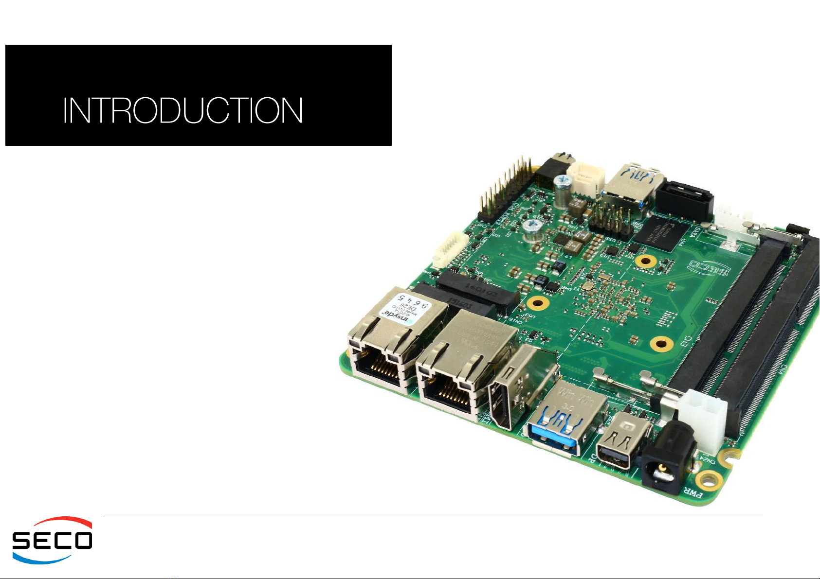
SBC with the N-series Intel®Pentium®/ Celeron®and
x5-Series Atom SoCs in the embedded NUC form
factor

SBC-A80-eNUC
SBC-A80-eNUC User Manual - Rev. First Edition: 1.0 - Last Edition: 1.2 - Author: S.B. - Reviewed by G.G Copyright © 2017 SECO S.r.l.
2
All rights reserved. All information contained in this manual is proprietary and confidential material of SECO S.r.l.
Unauthorized use, duplication, modification or disclosure of the information to a third-party by any means without prior consent of SECO S.r.l. is prohibited.
Every effort has been made to ensure the accuracy of this manual. However, SECO S.r.l. accepts no responsibility for any inaccuracies, errors or omissions herein.
SECO S.r.l. reserves the right to change precise specifications without prior notice to supply the best product possible.
Some of the information found in the BIOS SETUP Chapter has been extracted from the following copyrighted Insyde Software Corp. documents:
InsydeH2O Setup Utility - User Reference Guide
The above mentioned documents are copyright © 2008 Insyde Software Corp. All rights reserved.
For further information on this module or other SECO products, but also to get the required assistance for any and possible issues, please contact us using the
dedicated web form available at http://www.seco.com (registration required).
Our team is ready to assist.
Revision
Date
Note
Ref
1.0
8th April 2016
First Official Release.
SB
1.1
19th October 2016
Updated to rev. C of the PCB:
-M.2_ALERT# signal on connector CN16 added
-GPI/O Connector added
-Paragraph 3.3.16 title corrected
SB
1.2
15th March 2017
BIOS Section updated
SB
REVISION HISTORY

SBC-A80-eNUC
SBC-A80-eNUC User Manual - Rev. First Edition: 1.0 - Last Edition: 1.2 - Author: S.B. - Reviewed by G.G Copyright © 2017 SECO S.r.l.
3
INDEX
INTRODUCTION.......................................................................................................................................................................... 5Chapter 1.
1.1 Warranty........................................................................................................................................................................................................................................ 6
1.2 Information and assistance.............................................................................................................................................................................................................7
1.3 RMA number request..................................................................................................................................................................................................................... 7
1.4 Safety............................................................................................................................................................................................................................................ 8
1.5 Electrostatic discharges ................................................................................................................................................................................................................. 8
1.6 RoHS compliance.......................................................................................................................................................................................................................... 8
1.7 Terminology and definitions ............................................................................................................................................................................................................ 9
1.8 Reference specifications ..............................................................................................................................................................................................................11
OVERVIEW ............................................................................................................................................................................... 12Chapter 2.
2.1 Introduction.................................................................................................................................................................................................................................. 13
2.2 Technical specifications ...............................................................................................................................................................................................................14
2.3 Electrical specifications ................................................................................................................................................................................................................15
2.3.1 RTC Battery ................................................................................................................................................................................................................................................15
2.3.2 Power consumption.....................................................................................................................................................................................................................................16
2.3.3 Power rails naming convention .....................................................................................................................................................................................................................17
2.4 Mechanical specifications............................................................................................................................................................................................................. 18
2.5 Block diagram..............................................................................................................................................................................................................................19
CONNECTORS......................................................................................................................................................................... 20Chapter 3.
3.1 Introduction.................................................................................................................................................................................................................................. 21
3.2 Connectors overview ...................................................................................................................................................................................................................22
3.3 Connectors description................................................................................................................................................................................................................23
3.3.1 Ethernet connectors ....................................................................................................................................................................................................................................23
3.3.2 USB ports...................................................................................................................................................................................................................................................24
3.3.3 HDMI connector..........................................................................................................................................................................................................................................26
3.3.4 miniDP++ Connector...................................................................................................................................................................................................................................27
3.3.5 eDP Connector ...........................................................................................................................................................................................................................................28
3.3.6 T/S connector.............................................................................................................................................................................................................................................29
3.3.7 Audio interfaces...........................................................................................................................................................................................................................................30
3.3.8 Buttons / LED header ..................................................................................................................................................................................................................................31
3.3.9 Multi-standard serial ports............................................................................................................................................................................................................................32
3.3.10 μSD slot .....................................................................................................................................................................................................................................................33
3.3.11 S-ATA connectors.......................................................................................................................................................................................................................................33

SBC-A80-eNUC
SBC-A80-eNUC User Manual - Rev. First Edition: 1.0 - Last Edition: 1.2 - Author: S.B. - Reviewed by G.G Copyright © 2017 SECO S.r.l.
4
3.3.12 M.2 SSD Slot: Socket 2 Key B.....................................................................................................................................................................................................................34
3.3.13 M.2 Connectivity Slot: Key E Socket 1..........................................................................................................................................................................................................35
3.3.14 FAN connectors ..........................................................................................................................................................................................................................................36
3.3.15 GPI/O connector.........................................................................................................................................................................................................................................37
3.3.16 SO-DIMM DDR3L Slot.................................................................................................................................................................................................................................38
3.3.17 IR Receiver..................................................................................................................................................................................................................................................38
BIOS SETUP............................................................................................................................................................................. 39Chapter 4.
4.1 InsydeH2O setup Utility................................................................................................................................................................................................................40
4.2 Main setup menu.........................................................................................................................................................................................................................41
4.2.1 System Time / System Date.........................................................................................................................................................................................................................41
4.3 Advanced menu ..........................................................................................................................................................................................................................42
4.3.1 Boot configuration submenu.........................................................................................................................................................................................................................43
4.3.2 Security configuration (TXE) submenu...........................................................................................................................................................................................................43
4.3.3 Video configuration submenu.......................................................................................................................................................................................................................43
4.3.4 Chipset configuration submenu....................................................................................................................................................................................................................45
4.3.5 ACPI Table/features submenu......................................................................................................................................................................................................................47
4.3.6 SATA configuration submenu.......................................................................................................................................................................................................................48
4.3.7 Console Redirection submenu .....................................................................................................................................................................................................................49
4.3.8 POST Hot Key submenu..............................................................................................................................................................................................................................51
4.3.9 Other configuration submenu .......................................................................................................................................................................................................................51
4.4 Security menu..............................................................................................................................................................................................................................52
4.5 Power menu................................................................................................................................................................................................................................ 53
4.5.1 Advanced CPU control submenu .................................................................................................................................................................................................................54
4.5.2 EC Watchdog Configuration submenu..........................................................................................................................................................................................................55
4.5.3 Thermal Zone configuration submenu...........................................................................................................................................................................................................55
4.6 Boot menu ..................................................................................................................................................................................................................................56
4.6.1 Legacy submenu.........................................................................................................................................................................................................................................57
4.7 Exit menu ....................................................................................................................................................................................................................................58
APPENDICES............................................................................................................................................................................ 59Chapter 5.
5.1 Thermal Design............................................................................................................................................................................................................................60
5.2 Accessories.................................................................................................................................................................................................................................61
5.2.1 Accessories kit CABKITA80 .........................................................................................................................................................................................................................61
5.2.2 USB-to-Serial port converter modules...........................................................................................................................................................................................................62
SBC-A80-eNUC
SBC-A80-eNUC User Manual - Rev. First Edition: 1.0 - Last Edition: 1.2 - Author: S.B. - Reviewed by G.G Copyright © 2017 SECO S.r.l.
5
Chapter 1.
Warranty
Information and assistance
RMA number request
Safety
Electrostatic discharges
RoHS compliance
Terminology and definitions
Reference specifications

SBC-A80-eNUC
SBC-A80-eNUC User Manual - Rev. First Edition: 1.0 - Last Edition: 1.2 - Author: S.B. - Reviewed by G.G Copyright © 2017 SECO S.r.l.
6
1.1Warranty
This product is subject to the Italian Law Decree 24/2002, acting European Directive 1999/44/CE on matters of sale and warranties to consumers.
The warranty on this product lasts for 1 year.
Under the warranty period, the Supplier guarantees the buyer assistance and service for repairing, replacing or credit of the item, at the Supplier’s own discretion.
Shipping costs that apply to non-conforming items or items that need replacement are to be paid by the customer.
Items cannot be returned unless previously authorized by the supplier.
The authorization is released after completing the specific form available on the web-site http://www.seco.com/en/prerma (RMA Online). The RMA authorization
number must be put both on the packaging and on the documents shipped with the items, which must include all the accessories in their original packaging, with
no signs of damage to, or tampering with, any returned item.
The error analysis form identifying the fault type must be completed by the customer and has must accompany the returned item.
If any of the above mentioned requirements for the RMA is not satisfied, the item will be shipped back and the customer will have to pay any and all shipping costs.
Following a technical analysis, the supplier will verify if all the requirements, for which a warranty service applies, are met. If the warranty cannot be applied, the
Supplier will calculate the minimum cost of this initial analysis on the item and the repair costs. Costs for replaced components will be calculated separately.
Warning!
All changes or modifications to the equipment not explicitly approved by SECO S.r.l. could impair the equipment’
s functionalities and could void
the warranty

SBC-A80-eNUC
SBC-A80-eNUC User Manual - Rev. First Edition: 1.0 - Last Edition: 1.2 - Author: S.B. - Reviewed by G.G Copyright © 2017 SECO S.r.l.
7
1.2Information and assistance
What do I have to do if the product is faulty?
SECO S.r.l. offers the following services:
SECO website: visit http://www.seco.com to receive the latest information on the product. In most cases it is possible to find useful information to solve the
problem.
SECO Sales Representative: the Sales Rep can help to determine the exact cause of the problem and search for the best solution.
SECO Help-Desk: contact SECO Technical Assistance. A technician is at disposal to understand the exact origin of the problem and suggest the correct
solution. E-mail: technical.servic[email protected]
Fax (+39) 0575 340434
Repair centre: it is possible to send the faulty product to the SECO Repair Centre. In this case, follow this procedure:
oReturned items must be accompanied by a RMA Number. Items sent without the RMA number will be not accepted.
oReturned items must be shipped in an appropriate package. SECO is not responsible for damages caused by accidental drop, improper usage, or
customer neglect.
Note: Please have the following information before asking for technical assistance:
Name and serial number of the product;
Description of Customer’s peripheral connections;
Description of Customer’s software (operating system, version, application software, etc.);
A complete description of the problem;
The exact words of every kind of error message encountered.
1.3RMA number request
To request a RMA number, please visit SECO’s web-site. On the home page, please select “RMA Online”and follow the procedure described.
A RMA Number will be sent within 1 working day (only for on-line RMA requests).

SBC-A80-eNUC
SBC-A80-eNUC User Manual - Rev. First Edition: 1.0 - Last Edition: 1.2 - Author: S.B. - Reviewed by G.G Copyright © 2017 SECO S.r.l.
8
Always switch the power off, and unplug the power supply unit, before handling the board and/or connecting cables or other
boards.
Avoid using metallic components - like paper clips, screws and similar - near the board when connected to a power supply, to avoid
short circuits due to unwanted contacts with other board components.
If the board has become wet, never connect it to any external power supply unit or battery.
Check carefully that all cables are correctly connected and that they are not damaged.
Whenever handling a SBC-A80-eNUC board, ground yourself through an anti-static wrist strap. Placement of the board on an anti-
static surface is also highly recommended.
1.4Safety
The SBC-A80-eNUC board uses only extremely-low voltages.
While handling the board, please use extreme caution to avoid any kind of risk or damages to electronic components.
1.5Electrostatic discharges
The SBC-A80-eNUC board, like any other electronic product, is an electrostatic sensitive device: high voltages caused by static electricity could damage some or
all the devices and/or components on-board.
1.6RoHS compliance
The SBC-A80-eNUC board is designed using RoHS compliant components and is manufactured on a lead-free production line. It is therefore fully RoHS
compliant.

SBC-A80-eNUC
SBC-A80-eNUC User Manual - Rev. First Edition: 1.0 - Last Edition: 1.2 - Author: S.B. - Reviewed by G.G Copyright © 2017 SECO S.r.l.
9
1.7 Terminology and definitions
ACPI Advanced Configuration and Power Interface, an open industrial standard for the board’s devices configuration and power management
AHCI Advanced Host Controller Interface, a standard which defines the operation modes of SATA interface
API Application Program Interface, a set of commands and functions that can be used by programmers for writing software for specific Operating
Systems
BIOS Basic Input / Output System, the Firmware Interface that initializes the board before the OS starts loading
CEC Consumer Electronics Control, an HDMI feature which allows controlling more devices connected together by using only one remote control
DDC Display Data Channel, a kind of I2C interface for digital communication between displays and graphics processing units (GPU)
DDR Double Data Rate, a typology of memory devices which transfer data both on the rising and on the falling edge of the clock
DDR3L DDR, 3rd generation, Low voltage
DP++ Multimode Display Port, a video interface which can support both Display Port displays (directly) and HDMI/DVI displays (by using and external
adapter)
eDP embedded Display Port
FFC/FPC Flexible Flat Cable / Flat Panel Cable
GBE Gigabit Ethernet
Gbps Gigabits per second
GND Ground
GPI/O General purpose Input/Output
HD Audio High Definition Audio, most recent standard for hardware codecs developed by Intel®in 2004 for higher audio quality
HDMI High Definition Multimedia Interface, a digital audio and video interface
I2C Bus Inter-Integrated Circuit Bus, a simple serial bus consisting only of data and clock line, with multi-master capability
IoT Internet of Things
M.2 recent specifications for internal expansion modules, which defines many pinouts and sizes for different purposes. Can include SATA, PCI
Express, USB, UART, DP interfaces
Mbps Megabits per second
MMC/eMMC MultiMedia Card / embedded MMC, a type of memory card, having the same interface as the SD card. The eMMC is the embedded version of
the MMC. They are devices that incorporate the flash memories on a single BGA chip.
N.A. Not Applicable
N.C. Not Connected

SBC-A80-eNUC
SBC-A80-eNUC User Manual - Rev. First Edition: 1.0 - Last Edition: 1.2 - Author: S.B. - Reviewed by G.G Copyright © 2017 SECO S.r.l.
10
OpenCL Open Computing Language, a software library based on C99 programming language, conceived explicitly to realise parallel computing using
Graphics Processing Units (GPU)
OpenGL Open Graphics Library, an Open Source API dedicated to 2D and 3D graphics
OS Operating System
PCI-e Peripheral Component Interface Express
PSU Power Supply Unit
PWM Pulse Width Modulation
PWR Power
PXE Preboot Execution Environment, a way to perform the boot from the network ignoring local data storage devices and/or the installed OS
SATA Serial Advance Technology Attachment, a differential full duplex serial interface for Hard Disks
SD Secure Digital, a memory card type
SM Bus System Management Bus, a subset of the I2C bus dedicated to communication with devices for system management, like a smart battery and
other power supply-related devices
SPI Serial Peripheral Interface, a 4-Wire synchronous full-duplex serial interface which is composed of a master and one or more slaves, individually
enabled through a Chip Select line
TBM To be measured
TDP Thermal Design Power, an indication of the amount of heat generated by the processor that must be used for the design of the thermal solution.
TMDS Transition-Minimized Differential Signaling, a method for transmitting high speed serial data, normally used on DVI and HDMI interfaces
UEFI Unified Extensible Firmware Interface, a specification defining the interface between the OS and the board’s firmware. It is meant to replace the
original BIOS interface
USB Universal Serial Bus
V_REF Voltage reference Pin
xHCI eXtensible Host Controller Interface, Host controller for USB 3.0 ports, which can also manage USB 2.0 and USB1.1 ports
SBC-A80-eNUC
SBC-A80-eNUC User Manual - Rev. First Edition: 1.0 - Last Edition: 1.2 - Author: S.B. - Reviewed by G.G Copyright © 2017 SECO S.r.l.
11
1.8 Reference specifications
Here below it is a list of applicable industry specifications and reference documents.
Reference
Link
ACPI
http://www.acpi.info
AHCI
http://www.intel.com/content/www/us/en/io/serial-ata/ahci.html
DDC
http://www.vesa.org
embedded NUC
http://www.sget.org/fileadmin/_migrated/content_uploads/SGET_Specification_embedded_NUC_SFF_V100.pdf
Gigabit Ethernet
http://standards.ieee.org/about/get/802/802.3.html
HD Audio
http://www.intel.com/content/dam/www/public/us/en/documents/product-specifications/high-definition-audio-specification.pdf
HDMI
http://www.hdmi.org/index.aspx
I2C
http://www.nxp.com/documents/other/UM10204_v5.pdf
Intel®Front Panel I/O connectivity DG
http://www.formfactors.org/developer/specs/A2928604-005.pdf
M.2
http://pcisig.com/specifications
MMC/eMMC
http://www.jedec.org/committees/jc-649
OpenCL
http://www.khronos.org/opencl
OpenGL
http://www.opengl.org
PCI Express
http://www.pcisig.com/specifications/pciexpress
SATA
https://www.sata-io.org
SD Card Association
https://www.sdcard.org/home
SM Bus
http://www.smbus.org/specs
TMDS
http://www.siliconimage.com/technologies/tmds
UEFI
http://www.uefi.org
USB 2.0 and USB OTG
http://www.usb.org/developers/docs/usb_20_070113.zip
USB 3.0
http://www.usb.org/developers/docs/usb_30_spec_070113.zip
Intel®N-Series Pentium®/ Celeron®and
x5-Series Atom family
http://ark.intel.com/products/codename/66094/Braswell#@Embedded


SBC-A80-eNUC
SBC-A80-eNUC User Manual - Rev. First Edition: 1.0 - Last Edition: 1.2 - Author: S.B. - Reviewed by G.G Copyright © 2017 SECO S.r.l.
13
2.1Introduction
SBC-A80-eNUC is a Single Board Computer in embedded NUC form factor (just 101.6 x 101.6mm) based on the N-Series Intel®Pentium®/ Celeron®and x5-
Series Atom family of System-on-Chips (SoCs) formerly coded as Braswell, a series of Dual / Quad Core SoCs with 64-bit instruction set and very low TDP.
These SoCs embed all the features usually obtained by combination of CPU + platform controller hubs, all in one single IC, which allows, therefore, the system
minimisation and performance optimisation, which is essential for boards with sizes so reduced as for embedded NUC SBCs.
This single chip solution includes the memory controller, which gives support for up to 8GB of DDR3L-1600 SODIMM Memory.
All SoCs embed an Intel®Gen 8-LP graphic core, which offers high graphical performances, with support for Microsoft®DirectX11.1, OpenGL 4.2, OpenCL 1.2,
OpenGL ES 3.0 and HW acceleration for video decoding of HEVC, H.264, MPEG2, MVC, VC-1, WMV9, JPEG/MJPEG and VP8 video standards (for H.264, MVC
and JPEG/MJPEG also HW encoding is offered). This embedded GPU is able to drive three independent displays, by using the HDMI, the miniDP++ and eDP
interfaces. Any combinations of these video interfaces are supported.
Further features, managed directly by the N-Series Intel®Pentium®/ Celeron®and x5-Series Atom family of SoCs and included in SBC-A80-eNUC board, are two
SATA Channels (one used for the common SATA / SSD drives, the other used to implement a M.2 Socket 2 Key B SSD slot), microSD interface, five USB ports
(two USB 3.0 on standard Type-A sockets, one USB 2.0 on M.2 Socket 1 Key E Connectivity slot and two USB 2.0 on internal pin header), HD Audio, two UARTs
(which are made available with software-configurable RS-232 / RS-422 / RS-485 interface) and three PCI Express lanes (two PCI express lanes are used for the
implementation of two Gigabit Ethernet interfaces, the other is carried out on M.2 Socket 1 Key E Connectivity slot)
This board is suitable both for IoT applications, due to its rich connectivity, and for industrial applications, since it can accept supply voltages in the range +18VDC ÷
+ 32VDC (recommended voltage range).
The board offers the possibility of expansion by using M.2 modules (both for mass storage and connectivity expansion), which is one of the most recent standards
for expansion modules. This guarantees to the SBC-A80-eNUC board a wide possibility of expandability even for the future.
Please refer to following chapter for a complete list of all peripherals integrated and characteristics.

2.2Technical specifications
SoC
Intel®Pentium®N3710, Quad Core @1.6GHz (Turbo Boost 2.56GHz), 2MB
Cache, 6W TDP
Intel®Celeron®N3160, Quad Core @1.6GHz (Turbo Boost 2.24GHz), 2MB
Cache, 6W TDP
Intel®Celeron®N3060, Dual Core @1.6GHz (Turbo Boost 2.48GHz), 2MB
Cache, 6W TDP
Intel®Celeron®N3010, Dual Core @1.04GHz (Turbo Boost 2.24GHz), 2MB
Cache, 4W TDP
Intel®Atom x5-E8000, Quad Core @1.04GHz, 2MB Cache, 5W TDP
Memory
Up to 8GB Dual Channel on DDR3L-1600 SO-DIMM Slot *
Graphics
Integrated Intel®HD Graphics controller
Three independent display support
HW decoding of HEVC(H.265), H.264, MPEG2, MVC, VC-1, VP8, WMV9,
JPEG/MJPEG formats
HW encoding of H.264, MVC and JPEG/MPEG formats
Video Interfaces
HDMI connector
miniDP++ connector
embedded DisplayPort (eDP) internal connector
Video Resolution
HDMI, DP++, resolution up to 3840x2160 24bpp @30Hz, 2560x1600 24bpp
@60Hz
eDP, resolution up to 2560x1440 24bpp @60Hz
Mass Storage
Optional eMMC drive onboard
SATA 7p M connector
M.2 Key B SATA slot (Type 2242 or 2260 modules accepted)
microSD Card slot
* Please notice that total amount of 8GB would be usable only with 64-bit OS. Total
amount of memory available with a 32-bit OS depends on the OS itself (less than
4GB, however).
USB
2 x USB 3.0 Host ports on Type-A sockets
2 x USB 2.0 Host port on internal pin header
1 x USB 2.0 Host port on M.2 Connectivity slot
PCI-Express
1 x PCI-e x1 port on M.2 Connectivity Slot
Audio
HD Audio Codec Realtek ALC883
Combo TRSS connector with Mic In and Line out support
Audio available on HDMI and miniDP++ interface
Serial Ports
2 x RS-232 / RS-422 / RS-485 Serial ports on internal pin Header
Other Interfaces
8 x GPI/Os
I2C Touch Panel connector
Switch/LED Front Panel Header
CIR (Consumer InfraRed) Sensor
Power supply: +18VDC ÷ + 32VDC recommended
+15VDC ÷ +36VDC absolute
RTC Battery
Operating temperature: 0°C ÷ +60°C** (Commercial temperature)
Dimensions: 101.6 x 101.6 mm (4”x 4”).
Supported Operating Systems:
Microsoft®Windows®7 (32/64 bit)
Microsoft®Windows®8.1 (32/64 bit)
Microsoft®Windows®10 (32/64 bit)
Microsoft®Windows®10 IoT
Microsoft®Windows®Embedded Standard 7 /8 (32/64 bit)
Linux (32/64 bit)
** Temperatures indicated are the maximum temperature that the
heatspreader / heatsink can reach in any of its parts. This means that it is
customer
’
s responsibility to use any passive cooling solution along with an
application-dependent cooling system, capable to ensure that the
heatspreader / heatsink temperature remains in the range above indicated.
Please also check paragraph 5.1

CAUTION: handling batteries incorrectly or replacing with not-approved devices may present a risk of fire or explosion.
2.3Electrical specifications
The SBC-A80-eNUC board can be supplied with any voltage in the range +15VDC ÷ +36VDC (absolute voltage range)
Anyway, it is recommended that the supply voltage be in the +18VDC ÷ +32VDC range (recommended voltage range)
This voltage can be supplied through a standard 6.3mm (internal pin, diameter 2.0 mm) Power Jack (CN24). Internal pin is VIN power line.
As an alternative, the board can be equipped with an internal “mini-Fit”connector, type MOLEX p/n 39-28-1023 or
equivalent, which can be used for the connection of an external PSU.
Mating connector: MOLEX p/n 39-01-2020 or equivalent with crimp terminals series 5556/44476.
2.3.1 RTC Battery
For the occurrences when the module is not powered with an external power supply, on board there is a cabled coin Lithium Battery to supply, with a 3V voltage,
the Real Time Clock embedded inside the Intel®SoC.
Battery used is a cabled CR2032-LD Lithium coin-cell battery, with a nominal capacity of 220mAh.
The battery is not rechargeable, and can be connected to the board using dedicated connector CN5 which is a 2-pin
p1.27 mm type MOLEX p/n 53398-0271 or equivalent, with pinout shown in the table on the left.
Mating connector: MOLEX 51021-0200 receptacle with MOLEX 50079-8000 female crimp terminals.
In case of exhaustion, the battery should only be replaced with devices of the same type. Always check the orientation before
inserting and make sure that they are aligned correctly and are not damaged or leaking.
Never allow the batteries to become short-circuited during handling.
Batteries supplied with SBC-A80-eNUC are compliant to requirements of European Directive 2006/66/EC regarding batteries and accumulators. When putting out
of order SBC-A80-eNUC, remove the batteries from the board in order to collect and dispose them according to the requirement of the same European Directive
above mentioned. Even when replacing the batteries, the disposal has to be made according to these requirements.
Power IN connector - CN23
Pin
Signal
1
GND
2
VIN
Battery connector - CN1
Pin
Signal
1
VRTC
2
GND

SBC-A80-eNUC
SBC-A80-eNUC User Manual - Rev. First Edition: 1.0 - Last Edition: 1.2 - Author: S.B. - Reviewed by G.G Copyright © 2017 SECO S.r.l.
16
2.3.2 Power consumption
Using the following setup, and using all possible SoCs offered for SBC-A80-eNUC board, the current consumption (RMS) has been measured on the VIN Power
line when the board is supplied through DC power jack CN23 using a +19VDC Notebook DC Adapter.
O.S. Windows 10 Professional
4GB (Transcend p/n TS512MSK64W6H) or 8GB (Transcend p/n TS1GSK64W6H) DDR3L-1600MHz SODIMM
16 or 32GB eMMC onboard
USB mouse and keyboard connected
HDMI display connected, resolution 1920x1080.
Optional adapter module for audio jacks, pushbuttons and status LEDs connected.
Bios Release 1.00 Rc09
Independently by the SoC mounted onboard, the following power consumptions are common to all boards:
Status
SoC / Configuration
N3710
32GB eMMC
4GB RAM
N3160
32GB eMMC
8GB RAM
N3060
16GB eMMC
4GB RAM
N3010
16GB eMMC
4GB RAM
x5-E3800
Inrush current at boot
784mA
712mA
880mA
824mA
TBM
Idle, power saving configuration
230mA
190mA
192mA
195mA
TBM
OS Boot, power saving configuration
457mA
360mA
380mA
340mA
TBM
Video reproduction@720p, power saving
configuration
285mA
270mA
252mA
270mA
TBM
Video reproduction@1080p, power saving
configuration
343mA
333mA
292mA
296mA
TBM
3DMarkVantage benchmark, power saving
configuration
720mA
635mA
584mA
545mA
TBM
3DMarkVantage benchmark, maximum performance
(RMS value)
761mA
673mA
688mA
504mA
TBM
3DMarkVantage benchmark, maximum performance
(peak value)
976mA
992mA
1020mA
736mA
TBM

SBC-A80-eNUC
SBC-A80-eNUC User Manual - Rev. First Edition: 1.0 - Last Edition: 1.2 - Author: S.B. - Reviewed by G.G Copyright © 2017 SECO S.r.l.
17
Battery Backup power consumption: 8.6μA
Soft-Off State power consumption: 43.25mA
Suspend State power consumption: 53.60mA
Please consider that the power consumption depends strongly on the utilization scenario.
Please also consider that the SBC-A80-eNUC board can accept a wide voltage range; the efficiency of the DC/DC converters, necessary to generate all the
voltages used by the module itself and by the peripherals connected, varies with the rise of the input voltage.
For all these reasons, it is recommended to use PSU with a minimum voltage of 40W for basic functionalities
2.3.3 Power rails naming convention
In all the tables contained in this manual, Power rails are named with the following meaning:
_S: Switched voltages, i.e. power rails that are active only when the board is in ACPI’s S0 (Working) state. Examples: +3.3V_S, +5V_S.
_A: Always-on voltages, i.e. power rails that are active both in ACPI’s S0 (Working), S3 (Standby) and S5 (Soft Off) state. Examples: +5V_A, +3.3V_A.
Other suffixes are used for application specific power rails, which are derived from same voltage value of voltage switched rails, if it is not differently stated (for
example, +5VHDMI is derived from +5V_S, and so on).
SBC-A80-eNUC
SBC-A80-eNUC User Manual - Rev. First Edition: 1.0 - Last Edition: 1.2 - Author: S.B. - Reviewed by G.G Copyright © 2017 SECO S.r.l.
18
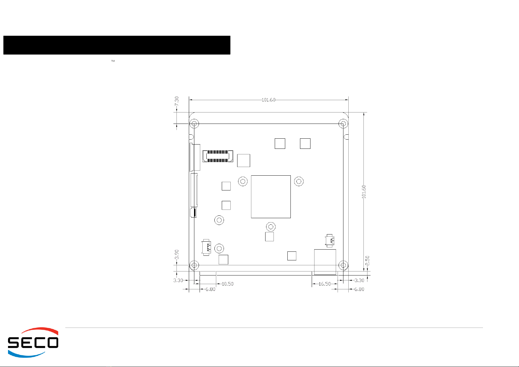
2.4 Mechanical specifications
According to embedded NUC form factor, board dimensions are 101.6 x 101.6 mm (4”x 4”).
The printed circuit of the board is made of ten layers, some of them are ground planes, for disturbance rejection.
SBC-A80-eNUC
SBC-A80-eNUC User Manual - Rev. First Edition: 1.0 - Last Edition: 1.2 - Author: S.B. - Reviewed by G.G Copyright © 2017 SECO S.r.l.
19
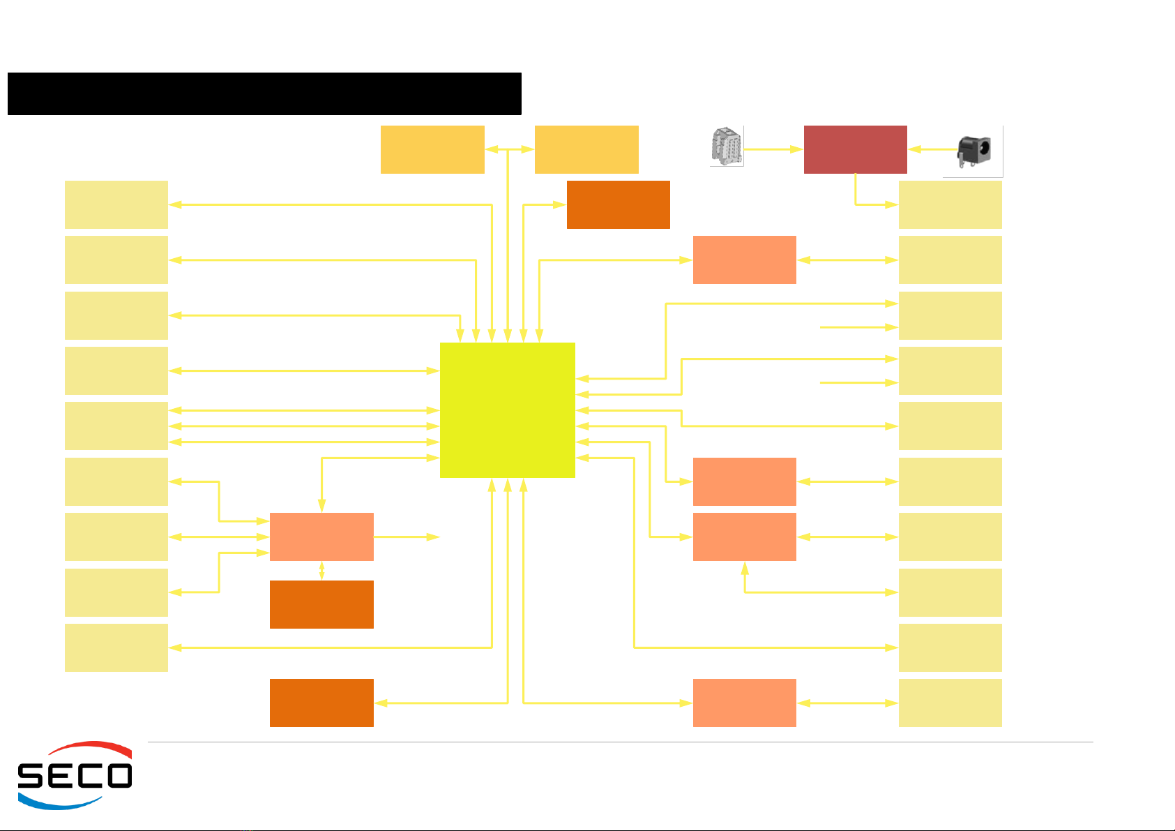
2.5 Block diagram
Microcontroller
2 x Realtek
RTL8111G Gigabit
Ethernet Controller
Power section
+18 ÷ +32VDC
DDR3L System
Memory (SODIMM)
SPI Flash
2 x Gigabit
Ethernet RJ-45
connectors
HDMI connector
miniDP++
connector
RS-232/RS-485
Serial port
transceiver
Serial port Internal
Header
Dual USB 2.0
internal pin header
M.2 SSD SATA slot
(Socket 2 Key B
Type 2242 / 2260)
SATA M 7p
connector
M.2 Connectivity
slot (Socket 1 Key
E Type 2230)
Buttons/LED
Header
IR receiver
PCI-e x1 #2
I2C #0
I2C #5 + INT + RST#
USB 2.0 ports #2 ÷ #3
SATA port #0
SATA Power
connector
Intel®
Braswell
family SoC
PCI-e x1 #0 ÷ #1
2 x USB 3.0 Type
A connectors
SATA port#1
DDI #1
USB port #4
SPI Flash
DDI #0
FAN Connector
SS USB ports #0 ÷ #1
Realtek ALC283
HD Audio Codec
2 x UART
DDI #2
DDR3L System
Memory (SODIMM)
TRRS combo
connector
CEC
CIR
CEC
eDP interface μSD Card
SD Interface
Speaker Internal
Header
T/S connector
eMMC Interface
SM Bus
CEC
I/O Expander
GPI/O connector
I2C #3
eMMC Disk

Other manuals for SBC Series
1
This manual suits for next models
1
Table of contents
Other Seco Motherboard manuals


