Seco Qseven CQ7-A42 User manual

CQ7-A42
Carrier Board for Qseven®Rel. 2.0
Compliant Modules on 3.5”form factor
CQ7-A42
CQ7-A42 - Rev. First Edition: 1.0 - Last Edition: 2.0 - Author: S.B. - Reviewed by G.G. Copyright © 2016 SECO S.r.l.
2
All rights reserved. All information contained in this manual is proprietary and confidential material of SECO S.r.l.
Unauthorised use, duplication, modification or disclosure of the information to a third-party by any means without prior consent of SECO S.r.l. is prohibited.
Every effort has been made to ensure the accuracy of this manual. However, SECO S.r.l. accepts no responsibility for any inaccuracies, errors or omissions herein.
SECO S.r.l. reserves the right to change precise specifications without prior notice to supply the best product possible.
For further information on this module or other SECO products, but also to get the required assistance for any and possible issues, please contact us using the
dedicated web form available at http://www.seco.com (registration required).
Our team is ready to assist you.
Revision
Date
Note
Rif
1.0
17th October 2014
First official release
SB
1.1
9th February 2015
Minor corrections.
CN21 pinout table corrected
SB
1.2
3rd March 2015
Optional LVDS connector CN16 description updated (warning added)
SB
1.3
8th June 2015
Audio modules added. Minor corrections
SB
2.0
26th January 2016
Product Name Change
SB
REVISION HISTORY

CQ7-A42
CQ7-A42 - Rev. First Edition: 1.0 - Last Edition: 2.0 - Author: S.B. - Reviewed by G.G. Copyright © 2016 SECO S.r.l.
3
INDEX
INTRODUCTION.......................................................................................................................................................................... 5Chapter 1.
1.1 Warranty........................................................................................................................................................................................................................................ 6
1.2 Information and assistance............................................................................................................................................................................................................. 7
1.3 RMA number request..................................................................................................................................................................................................................... 7
1.4 Safety............................................................................................................................................................................................................................................ 8
1.5 Electrostatic Discharges................................................................................................................................................................................................................. 8
1.6 RoHS compliance.......................................................................................................................................................................................................................... 8
1.7 Terminology and definitions ............................................................................................................................................................................................................ 9
1.8 Reference specifications ..............................................................................................................................................................................................................11
OVERVIEW ............................................................................................................................................................................... 12Chapter 2.
2.1 Introduction..................................................................................................................................................................................................................................13
2.2 Technical Specifications...............................................................................................................................................................................................................14
2.3 Electrical Specifications................................................................................................................................................................................................................15
2.3.1 RTC Battery......................................................................................................................................................................................................................... 15
2.3.2 Power Rails meanings..........................................................................................................................................................................................................16
2.4 Mechanical Specifications............................................................................................................................................................................................................16
2.5 Block Diagram .............................................................................................................................................................................................................................17
CONNECTORS......................................................................................................................................................................... 18Chapter 3.
3.1 Connectors placement.................................................................................................................................................................................................................19
3.2 Connectors overview ...................................................................................................................................................................................................................20
3.2.1 Connectors list.....................................................................................................................................................................................................................20
3.2.2 Jumpers list.........................................................................................................................................................................................................................20
3.3 Connectors description................................................................................................................................................................................................................21
3.3.1 Qseven®Connector.............................................................................................................................................................................................................21
3.3.2 Boot alternate jumper...........................................................................................................................................................................................................25
3.3.3 Ethernet connectors.............................................................................................................................................................................................................26
3.3.4 USB connectors ..................................................................................................................................................................................................................27
3.3.5 DP++/HDMI connectors.......................................................................................................................................................................................................29
3.3.6 Embedded LCD displays connectors....................................................................................................................................................................................31
3.3.7 Audio Interface.....................................................................................................................................................................................................................34

CQ7-A42
CQ7-A42 - Rev. First Edition: 1.0 - Last Edition: 2.0 - Author: S.B. - Reviewed by G.G. Copyright © 2016 SECO S.r.l.
4
3.3.8 Switch / LED header interface ..............................................................................................................................................................................................35
3.3.9 S-ATA connectors ...............................................................................................................................................................................................................36
3.3.10 mSATA slot.......................................................................................................................................................................................................................... 37
3.3.11 miniPCI-express slot ............................................................................................................................................................................................................38
3.3.12 μSD + miniSIM combo card slot...........................................................................................................................................................................................39
3.3.13 Serial ports ..........................................................................................................................................................................................................................40
3.3.14 CAN terminal block ..............................................................................................................................................................................................................41
3.3.15 LPC/GPIO Pin header ..........................................................................................................................................................................................................42
3.3.16 SPI Pin header.....................................................................................................................................................................................................................42
3.3.17 Feature internal pin header ...................................................................................................................................................................................................43
3.3.18 GPIO internal pin header ......................................................................................................................................................................................................44
3.3.19 FAN Connector....................................................................................................................................................................................................................44
3.3.20 Optional Manufacturer and Debug Connectors .....................................................................................................................................................................45
Appendices.............................................................................................................................................................................. 46Chapter 4.
4.1 Thermal Design............................................................................................................................................................................................................................47
4.2 Accessories.................................................................................................................................................................................................................................48
4.2.1 Accessories kit CABKITA42..................................................................................................................................................................................................48
4.2.2 HD Audio Adapter module VA67 ..........................................................................................................................................................................................48
4.2.3 I2S Audio Adapter module VA74 ..........................................................................................................................................................................................48


CQ7-A42
CQ7-A42 - Rev. First Edition: 1.0 - Last Edition: 2.0 - Author: S.B. - Reviewed by G.G. Copyright © 2016 SECO S.r.l.
6
1.1Warranty
This product is subject to the Italian Law Decree 24/2002, acting European Directive 1999/44/CE on matters of sale and warranties to consumers.
The warranty on this product lasts 1 year.
Under the warranty period, the Supplier guarantees the buyer assistance and service for repairing, replacing or credit of the item, at the Supplier’s own discretion.
Shipping costs that apply to non-conforming items or items that need replacement are to be paid by the customer.
Items cannot be returned unless previously authorised by the supplier.
The authorisation is released after completing the specific form available on the web-site http://www.seco.com/en/prerma (RMA Online). The RMA authorisation
number must be put both on the packaging and on the documents shipped with the items, which must include all the accessories in their original packaging, with
no signs of damage to, or tampering with, any returned item.
The error analysis form identifying the fault type must be completed by the customer and must accompany the returned item.
If any of the above mentioned requirements for RMA is not satisfied, the item will be shipped back and the customer will have to pay any and all shipping costs.
Following a technical analysis, the supplierwill verify if all the requirements for which a warranty service applies are met. If the warranty cannot be applied, the
Supplier will calculate the minimum cost of this initial analysis on the item and the repair costs. Costs for replaced components will be calculated separately.
Warning!
All changes or modifications to the equipment not explicitly approved by SECO S.r.l. could impair the equipment and could void the warranty.

CQ7-A42
CQ7-A42 - Rev. First Edition: 1.0 - Last Edition: 2.0 - Author: S.B. - Reviewed by G.G. Copyright © 2016 SECO S.r.l.
7
1.2Information and assistance
What do I have to do if the product is faulty?
SECO S.r.l. offers the following services:
SECO website: visit http://www.seco.com to receive the latest information on the product. In most cases it is possible to find useful information to solve the
problem.
SECO Sales Representative: the Sales Rep can help to determine the exact cause of the problem and search for the best solution.
SECO Help-Desk: contact SECO Technical Assistance. A technician is at disposal to understand the exact origin of the problem and suggest the correct
solution. E-mail: technical.se[email protected]
Fax (+39) 0575 340434
Repair centre: it is possible to send the faulty product to the SECO Repair Centre. In this case, follow this procedure:
oReturned items must be accompanied by a RMA Number. Items sent without the RMA number will be not accepted.
oReturned items must be shipped in an appropriate package. SECO is not responsible for damages caused by accidental drop, improper usage, or
customer neglect.
Note: Please have the following information before requesting for technical assistance:
-Name and serial number of the product;
-Description of Customer’s peripheral connections;
-Description of Customer’s software (operating system, version, application software, etc.);
-A complete description of the problem;
-The exact words of every kind of error message encountered.
1.3RMA number request
To request a RMA number, please visit SECO’s web-site. On the home page, please select “RMA Online”and follow the procedure described.
A RMA Number will be released within 1 working day (only for on-line RMA requests).

CQ7-A42
CQ7-A42 - Rev. First Edition: 1.0 - Last Edition: 2.0 - Author: S.B. - Reviewed by G.G. Copyright © 2016 SECO S.r.l.
8
Whenever handling a CQ7-A42 board, ground yourself through an anti-static wrist strap. Placement of the board on an anti-static
surface is also highly recommended.
1.4Safety
The CQ7-A42 board uses only extremely-low voltages.
While handling the board, please use extreme caution to avoid any kind of risk or damages to electronic components.
1.5 Electrostatic Discharges
The CQ7-A42 board, like any other electronic product, is an electrostatic sensitive device: high voltages caused by static electricity could damage some or all the
devices and/or components on-board.
1.6 RoHS compliance
The CQ7-A42 board is designed using RoHS compliant components and is manufactured on a lead-free production line. It is therefore fully RoHS compliant.
Always switch the power off, and unplug the power supply unit, before handling the board and/or connecting cables or other
boards.
Avoid using metallic components - like paper clips, screws and similar - near the board when connected to a power supply, to avoid
short circuits due to unwanted contacts with other board components.
If the board has become wet, never connect it to any external power supply unit or battery.
Check carefully that all cables are correctly connected and that they are not damaged.

CQ7-A42
CQ7-A42 - Rev. First Edition: 1.0 - Last Edition: 2.0 - Author: S.B. - Reviewed by G.G. Copyright © 2016 SECO S.r.l.
9
1.7 Terminology and definitions
ACPI Advanced Configuration and Power Interface, an open industrial standard for the board’s devices configuration and power management
AC’97 Audio Codec’97, a standard for audio hardware codecs developed by Intel®in 1997
API Application Program Interface, a set of commands and functions that can be used by programmers for writing software for specific Operating
Systems
BIOS Basic Input / Output System, the Firmware Interface that initializes the board before the OS starts loading
CEC Consumer Electronics Control, an HDMI feature which allows controlling more devices connected together by using only one remote control
DDC Display Data Channel, a kind of I2C interface for digital communication between displays and graphics processing units (GPU)
DP Display Port, a type of digital video display interface
DVI Digital Visual interface, a type of digital video display interface
eDP embedded Display Port, a type of digital video display interface developed especially for internal connections between boards and digital
displays
GbE Gigabit Ethernet
Gbps Gigabits per second
GND Ground
GPI/O General purpose Input/Output
HD Audio High Definition Audio, most recent standard for hardware codecs developed by Intel®in 2004 for higher audio quality
HDMI High Definition Multimedia Interface, a digital audio and video interface
I2C Bus Inter-Integrated Circuit Bus, a simple serial bus consisting only of data and clock line, with multi-master capability
I2S Inter-Integrated Circuit Sound, an audio serial bus protocol interface developed by Philips (now NXP) in 1986
JTAG Joint Test Action Group, common name of IEEE1149.1 standard for testing printed circuit boards and integrated circuits through the Debug port
LPC Bus Low Pin Count Bus, a low speed interface based on a very restricted number of signals, deemed to management of legacy peripherals
LVDS Low Voltage Differential Signalling, a standard for transferring data at very high speed using inexpensive twisted pair copper cables, usually used
for video applications
Mbps Megabits per second
N.A. Not Applicable
N.C. Not Connected
OS Operating System
PCI-e Peripheral Component Interface Express

CQ7-A42
CQ7-A42 - Rev. First Edition: 1.0 - Last Edition: 2.0 - Author: S.B. - Reviewed by G.G. Copyright © 2016 SECO S.r.l.
10
PSU Power Supply Unit
PWM Pulse Width Modulation
PWR Power
SATA Serial Advance Technology Attachment, a differential half duplex serial interface for Hard Disks
SD Secure Digital, a memory card type
SDIO Secure Digital Input/Output, an evolution of the SD standard that allows the use of the same SD interface to drive different Input/Output devices,
like cameras, GPS, Tuners and so on
SIM Subscriber Identity Module, a card which stores all data of the owner necessary to allow him accessing to mobile communication networks
SM Bus System Management Bus, a subset of the I2C bus dedicated to communication with devices for system management, like a smart battery and
other power supply-related devices
SPI Serial Peripheral Interface, a 4-Wire synchronous full-duplex serial interface which is composed a master and one or more slaves, individually
enabled through a Chip Select line
TBM To be measured
TMDS Transition-Minimized Differential Signalling, a method for transmitting high speed serial data, normally used on DVI and HDMI interfaces
TTL Transistor-transistor Logic
UIM User Identity Module, an extension of SIM modules.
USB Universal Serial Bus
V_REF Voltage reference Pin
CQ7-A42
CQ7-A42 - Rev. First Edition: 1.0 - Last Edition: 2.0 - Author: S.B. - Reviewed by G.G. Copyright © 2016 SECO S.r.l.
11
1.8 Reference specifications
Here below it is a list of applicable industry specifications and reference documents.
Reference
Link
ACPI
http://www.acpi.info
AC’97
http://download.intel.com/support/motherboards/desktop/sb/ac97_r23.pdf
DDC
http://www.vesa.org
DP, eDP
http://www.vesa.org
Gigabit Ethernet
http://standards.ieee.org/about/get/802/802.3.html
HD Audio
http://www.intel.com/content/dam/www/public/us/en/documents/product-specifications/high-definition-audio-specification.pdf
HDMI
http://www.hdmi.org/index.aspx
I2C
http://www.nxp.com/documents/other/UM10204_v5.pdf
I2S
https://www.sparkfun.com/datasheets/BreakoutBoards/I2SBUS.pdf
LPC Bus
http://www.intel.com/design/chipsets/industry/lpc.htm
LVDS
http://www.ti.com/ww/en/analog/interface/lvds.shtml
http://www.ti.com/lit/ml/snla187/snla187.pdf
PCI Express
http://www.pcisig.com/specifications/pciexpress
Qseven®specifications
http://www.sget.org/uploads/media/Qseven-Spec_2.0_SGET.pdf
Qseven®Errata to Rel. 2.0
http://www.sget.org/uploads/media/Qseven-Spec_2.0_SGET_errata_sheet_E2.00-001.pdf
SATA
https://www.sata-io.org
SD Card Association
https://www.sdcard.org/home
SM Bus
http://www.smbus.org/specs
TMDS
http://www.siliconimage.com/technologies/tmds
USB 2.0 and USB OTG
http://www.usb.org/developers/docs/usb_20_070113.zip
USB 3.0
http://www.usb.org/developers/docs/usb_30_spec_070113.zip


CQ7-A42
CQ7-A42 - Rev. First Edition: 1.0 - Last Edition: 2.0 - Author: S.B. - Reviewed by G.G. Copyright © 2016 SECO S.r.l.
13
2.1Introduction
CQ7-A42 is a carrier board for Qseven®rel. 2.0 compliant modules, in 3.5”mechanical Form Factor. It is specifically designed to support all features introduced
with release 2.0 of the specifications, including those introduced with the Errata to rel. 2.0 published by SGET consortium.
Qseven®is a form factor designed to minimize space consumption, since it integrates in only 70x70mm of space all core components of a common PC
architecture (CPU, RAM, Graphic, audio, etc.). All the functionalities are made available through a standardized card edge connector, from which all signals can be
taken and carried to the appropriate external connector in the carrier board and/or to other internal component, to implement more functionalities other than
included in the standard Qseven®bus interface.
The connection to the Qseven®board is implemented through a standardized MXM connector, which is a proven high speed signal interface connector.
The board has been specifically designed for taking advantage of all possible features that can be offered by x86 and/or ARM architectures on Qseven®modules.
All the features on the CQ7-A42 board are implemented according to the Qseven®standard bus interface, thus the board is fully Qseven®Rel. 2.0 compliant and
compatible with Qseven®Spec. 2.0 modules.
The list of features that are effectively available depends on the configuration of the carrier board and of the Qseven®module used.
CQ7-A42 board is specially designed for being both an advanced development board, for skilled users who want to design their own carrier boards, and a good
solution for mass production, for customers whose needing are satisfied by this compact and versatile Carrier Board.
All the components mounted onboard are certified for industrial temperature range.
CQ7-A42
CQ7-A42 - Rev. First Edition: 1.0 - Last Edition: 1.3 - Author: S.B. - Reviewed by G.G. Copyright © 2015 SECO S.r.l.
14
2.2Technical Specifications
Supported Modules
Qseven®Rel. 2.0 compliant modules
Mass Storage interfaces
1 x S-ATA connector with HDD Power connector
1 x mSATA Slot
microSD Slot on combo microSD + SIM connector
Video Interfaces
LVDS Dual Channel 24-bit + backlight connectors or 2 x eDP connectors
Multimode Display Port or HDMI Connector
Audio
Audio interface on internal pin header
USB
1 x USB3.0 Host port on type-A socket
2 x USB2.0 Host ports on double Type-A sockets
2 x USB2.0 Host ports on internal pin header
1 x USB 2.0 OTG port on micro-AB socket (USB port shared with miniPCI-e slot)
PCI Express
miniPCI-e slot Full/Half Size, combined with SIM card slot
Networking
Up to 2 x Gigabit Ethernet connectors
Serial Ports
4-wires RS-232/RS-422/RS-485 configurable serial port on DB9 male connector
2 x RS-232 Full-modem serial ports on internal header (need LPC interface from
Qseven®module)
CAN interface on PCB terminal block
Other Interfaces
SPI internal pin header
LPC Bus internal pin header
SM Bus / I2C GPIO expander, makes available 16 x GPIOs on internal pin header
Front Panel Header
1 x 28 pin connector for additional features (I2C, ACPI signals, SM Bus, Watch
Dog, Thermal Management)
+12V Tachometric FAN connector
Optional Debug USB port on miniB socket
Optional MFG connector for JTAG programming of Qseven®module
Power supply voltage: +12VDC Mini-fit Standard ATX power connector
Coin cell battery Holder for CMOS and RTC
Operating temperature: -40°C ÷ +85°C (industrial temperature range)
Dimensions: 146 x 102 mm (5.75”x 4.02”)
* Temperature ranges indicated mean that all components available onboard
are certified for working with a Tcase included in these temperature ranges.
This means that it is customer
’
s responsibility to ensure that all components
’
Tcases remain in the range above indicated. Please also check paragraph
4.1.
CQ7-A42
CQ7-A42 - Rev. First Edition: 1.0 - Last Edition: 2.0 - Author: S.B. - Reviewed by G.G. Copyright © 2016 SECO S.r.l.
15
CAUTION: handling batteries incorrectly or replacing with not-approved devices may present a risk of fire or explosion.
2.3Electrical Specifications
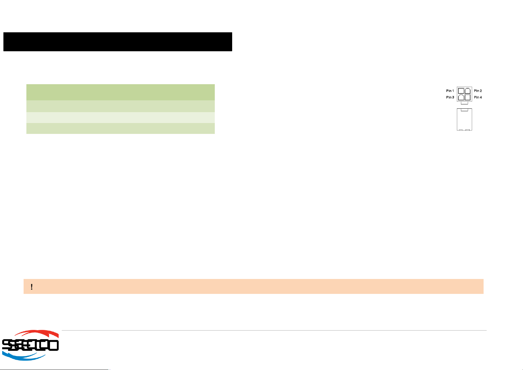
CQ7-A42 board needs to be supplied using a standard ATX Power Supply (only +12VDC ± 5% voltage is needed).
Power Connector is type Molex Mini-Fit Jr., p/n 39-28-1043, or equivalent, with the pinout indicated in the following table.
Mating Connector, MOLEX p/n 39-01-2040 or equivalent, with female crimp
terminal MOLEX series 5566. The use of wires with section 18 AWG or
20AWG is recommended, in order to ensure the proper amperage of the
power section.
All remaining voltages needed for board’s working are derived internally from
+12V_A power rail.
When choosing the power supply for CQ7-A42 board, please consider well what is the typical scenario for using the board (i.e., which peripherals will be
connected).
Internal power section is able to supply a maximum of 12A @ 5V and 4A @ 3.3V for Qseven module and for the external devices supplied directly by the carrier
board (i.e. USB devices, optionally SSD or SATA disks, display).
Since also 12V voltage can be drawn from the carrier board to supply other external peripherals (like Audio adapter modules, HDD, display Backlight, FAN), it is
very important to balance well the typical final configuration, summing all possible power consumptions.
This way it is possible to choose a PSU capable to supply enough current for the whole system.
2.3.1 RTC Battery
For the occurrences when the system (Carrier Board + Qseven®module) is not powered with an external power supply, on board there is a horizontal battery
holder, for the use of standard coin battery type BR2032 with a nominal capacity of 220mAh, to supply, with a 3V voltage, the Real Time Clock and CMOS
memory mounted on the Qseven®module.
The batteries should only be replaced with devices of the same type. Always check the orientation before inserting and make sure that they are aligned correctly
and are not damaged or leaking.
Never allow the batteries to become short-circuited during handling.
Batteries supplied with CQ7-A42 board are compliant to requirements of European Directive 2006/66/EC regarding batteries and accumulators. When putting out
of order CQ7-A42 board, remove the batteries from the board in order to collect and dispose them according to the requirement of the same European Directive
above mentioned. Even when replacing the batteries, the disposal has to be made according to these requirements.
Power Connector - CN21
Pin
Signal
Pin
Signal
1
GND
3
+12V_A
2
GND
4
+12V_A
CQ7-A42
CQ7-A42 - Rev. First Edition: 1.0 - Last Edition: 2.0 - Author: S.B. - Reviewed by G.G. Copyright © 2016 SECO S.r.l.
16
2.3.2 Power Rails meanings
In all the tables contained in this manual, Power rails are named with the following meaning:
_S: Switched voltages, i.e. power rails that are active only when the board is in ACPI’s S0 (Working) state. Examples: +3.3V_S, +5V_S.
_A: Always-on voltages, i.e. power rails that are active both in ACPI’s S0 (Working), S3 (Standby) and S5 (Soft Off) state. Examples: +5V_A, +3.3V_A.
_U: unswitched ACPI S3 voltages, i.e. power rails that are active both in ACPI’s S0 (Working) and S3 (Standby) state. Examples: +1.5V_U
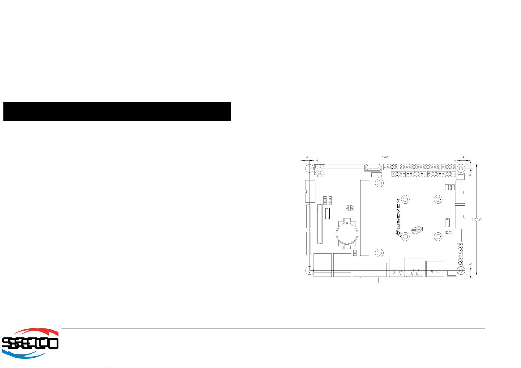
2.4 Mechanical Specifications
The board dimensions: 147 x 102 mm (5.79”x 4.02”).
Printed circuit of the board is made of eight layers, some of them are ground planes, for disturbance rejection.
In order to fix the Qseven®module to the carrier board, on CQ7-A42 are soldered two
metallic spacers (those farthest from MXM connector), height 7mm, 2.5mm diameter, that
can be used for the fixing of standard size Qseven®modules.
As a factory alternative, it is possible to solder two spacers for fixing of μQseven®modules:
this factory alternative has been done since the spacers needed for fixing of μQseven®
modules would interfere with electronic devices soldered on standard Qseven®modules.
Optionally, other two metallic spacers (those nearest to the MXM connector) can be
soldered on the carrier board, in order to have four fixing points and improve the mechanical
stability of the system
Considering possible application scenarios, please take notice of what kind of modules it
could be possible to use, before purchasing one of the possible configurations.
CQ7-A42
CQ7-A42 - Rev. First Edition: 1.0 - Last Edition: 2.0 - Author: S.B. - Reviewed by G.G. Copyright © 2016 SECO S.r.l.
17
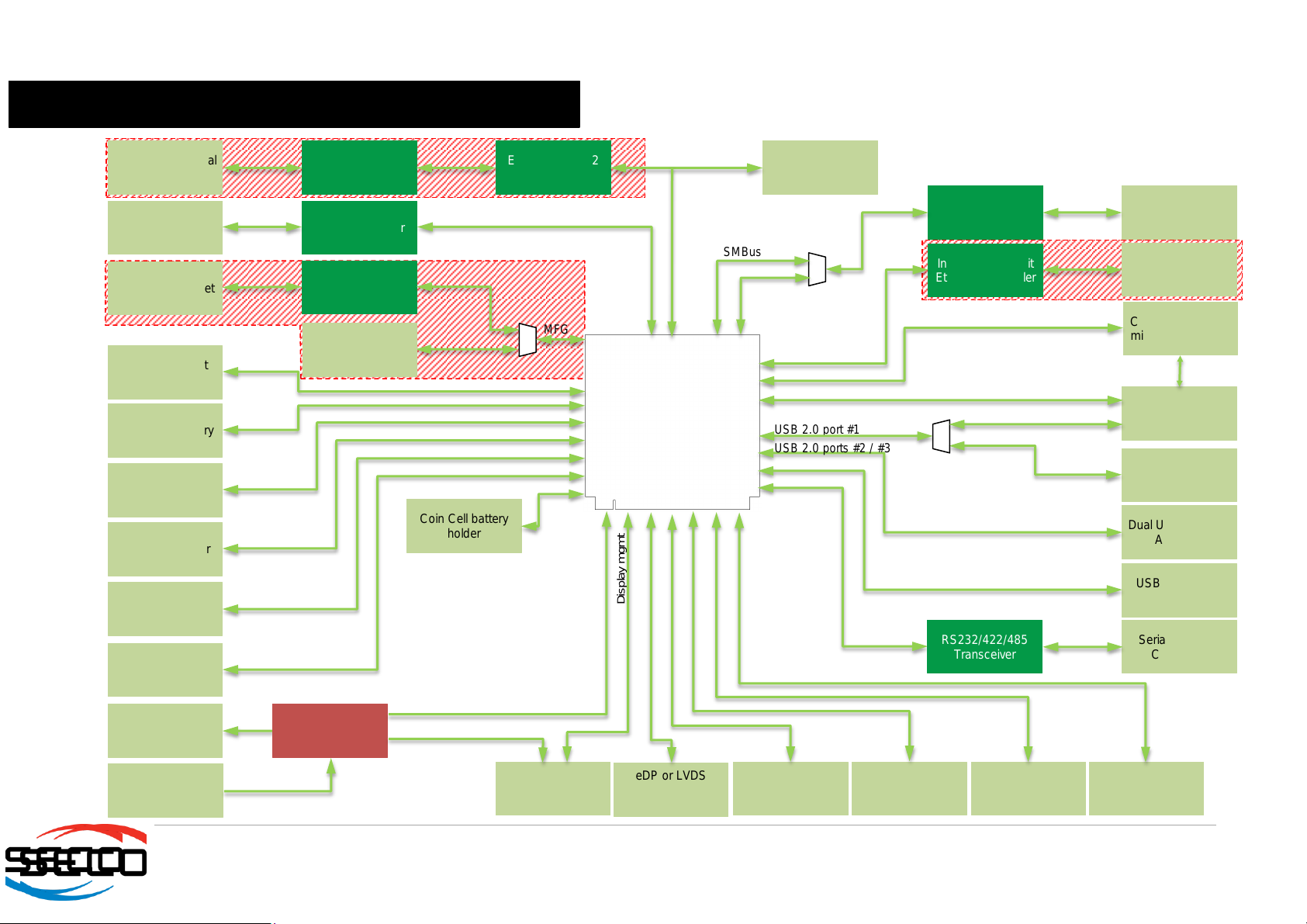
2.5 Block Diagram
OPTIONAL
Intel®I210 Gigabit
Ethernet Controller
Combo microSD +
miniSIM connector
OPTIONAL
Gigabit Ethernet
Connector #1
miniPCI-e Slot
micro-AB USB
OTG Socket
Dual USB 2.0 Type
A Socket
USB 3.0 Type A
Socket
2 x RS-232 internal
header
3-poles CAN
Terminal Block
USB miniB Socket
Gigabit Ethernet
Connector #0
mSATA Slot
SATA Connector
Audio internal
header
2 x USB 2.0
header
HDMI or DP++
connector (factory
option)
HDD Power
CAN Transceiver
UART-to-USB
bridge
2 x RS-232
Transceiver EXAR XR28V382
SuperI/O
Serial port DB9
Connector
ON Semiconductor
CAT9555 I/O
Expander
GPIO header
LPC Bus/GPIO
header
LCD display power
eDP or LVDS
header (factory
option)
SPI internal header
Front Panel header
FAN connector Feature internal
header
RS232/422/485
Transceiver
Coin Cell battery
holder
Power
Section
Mini-Fit Power
connector
SMBus
PCIe lane #1 or #2
SD interface
PCIe lane #0
USB 2.0 port #1
USB 2.0 ports #2 / #3
USB 3.0 port #0
UART
LPC Bus
CAN
Debug UART
MFG
Gigabit Ethernet
HDMI/DP++
SATA lane #0
SATA lane #1
Audio interface
USB 2.0 ports #4/#5
VCC_RTC
eDP/LVDS
SPI Interface
Various
FAN
Various
Display mgmt
+5V_S, +5V_A
Qseven MXM
connector
OPTIONAL
USB 2.0 port #1 Host
USB 2.0 port #1 OTG
I2C Bus
MFG connector

CQ7-A42
CQ7-A42 - Rev. First Edition: 1.0 - Last Edition: 2.0 - Author: S.B. - Reviewed by G.G. Copyright © 2016 SECO S.r.l.
19
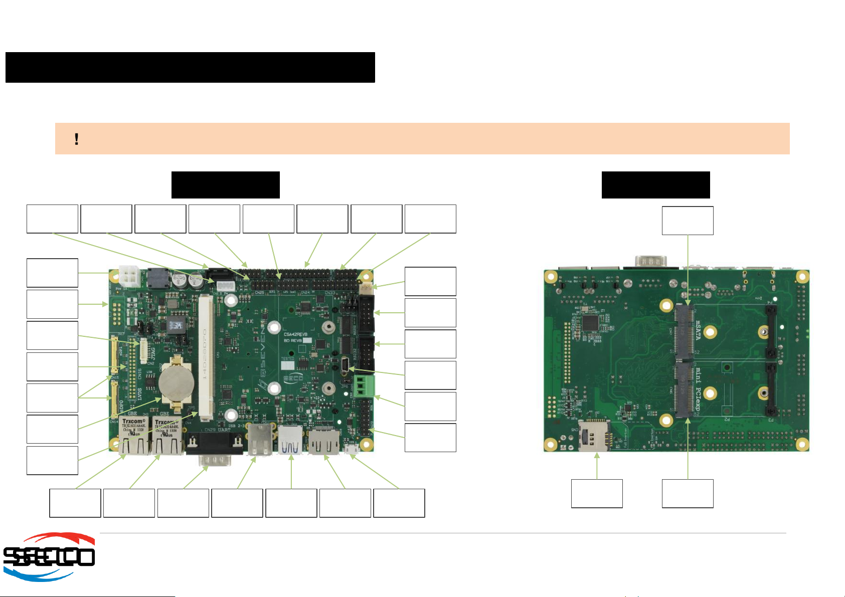
3.1Connectors placement
On CQ7-A42 carrier board, there are several connectors. Standard connectors are placed on the same side of PCB, so that it is possible to place them on a panel
of an eventual enclosure.
Please be aware that, depending on the configuration purchased, the appearance of the board could be different from the following pictures.
TOP SIDE
BOTTOM SIDE
Optional
backlight
CAN terminal
block
SATA Power
Qseven®
connector
SATA Port
#1
SPI Interface
USB ports
#4÷#5
header
Optional eDP
connectors
Battery
Holder
Optional
Gigabit
Ethernet #1
Gigabit
Ethernet #0
RS-232/RS-
422/RS-485
DB9 port
USB ports
#2÷#3
USB port #0
RS-232
Serial #1
RS-232
Serial #2
Optional
Debug USB
Audio
Interface
HDMI or
DP++
connector
Optional
LVDS
Optional
Manufacturer
USB port #1
FAN
LPC Feature
Switch/LED
header
GPIO header
Power In
μSD +
miniSIM
combo slot
miniPCI-e
slot
mSATA slot

CQ7-A42
CQ7-A42 - Rev. First Edition: 1.0 - Last Edition: 2.0 - Author: S.B. - Reviewed by G.G. Copyright © 2016 SECO S.r.l.
20
3.2 Connectors overview
3.2.1 Connectors list
Name
Description
Name
Description
CN1
Qseven®connector
CN18
Optional multimode Display Port connector
CN2
Manufacturer connector (reserved)
CN19
Optional HDMI connector
CN3
Optional Gigabit Ethernet port #1
CN20
Switch / LED Header Interface
CN4
Gigabit Ethernet port #0
CN21
Power In connector
CN5
μSD + miniSIM Combo Slot
CN22
Battery holder
CN6
miniPCI-e slot
CN23
FAN connector
CN7
mSATA slot
CN24
LPC internal Pin Header
CN8
SATA port#1 male connector
CN25
SPI internal Pin Header
CN9
Power connector for SATA #1 male
CN26
CAN terminal block
CN10
USB 2.0 ports #4-5 pin header
CN27
Optional Debug USB port
CN11
USB 2.0 type A ports #2 / #3
CN28
Audio interface internal pin header
CN12
USB 3.0 type A port #0
CN29
DB9 male configurable RS-232 / RS-422 / RS-485 serial port
CN13
USB 2.0 type micro-AB port #1
CN30
Feature internal pin header
CN14
Optional embedded Display Port #0
CN31
RS-232 Serial Port #1 internal pin header
CN15
Optional embedded Display Port port#1
CN32
RS-232 Serial Port #2 internal pin header
CN16
Optional LVDS interface
CN33
GPIO internal pin header
CN17
Optional backlight connector
3.2.2 Jumpers list
Name
Description
Name
Description
JP1
JTAG or Debug UART selector
JP6
CAN termination
JP2
USB port#1 routing (OTG connector or miniPCI-e slot)
JP7
RS-232/RS-485 selector
JP3
Backlight Voltage selector
JP8
RS-485 Half/Full Duplex selector
JP4
LCD Voltage selector
JP9
GPIO Bus interface selection
JP5
Boot_Alternate# Jumper
Table of contents
Other Seco Motherboard manuals


Popular Motherboard manuals by other brands


MATSONIC
MATSONIC MS7192S user manual

Diamond Systems
Diamond Systems Hercules II Fast start guide

MSI
MSI MS-6163VA user manual

Linear Technology
Linear Technology Demo Circuit 1592A quick start guide

Fairchild
Fairchild ON Semiconductor FSA642 user guide

Texas Instruments
Texas Instruments TVP5146EVM user guide