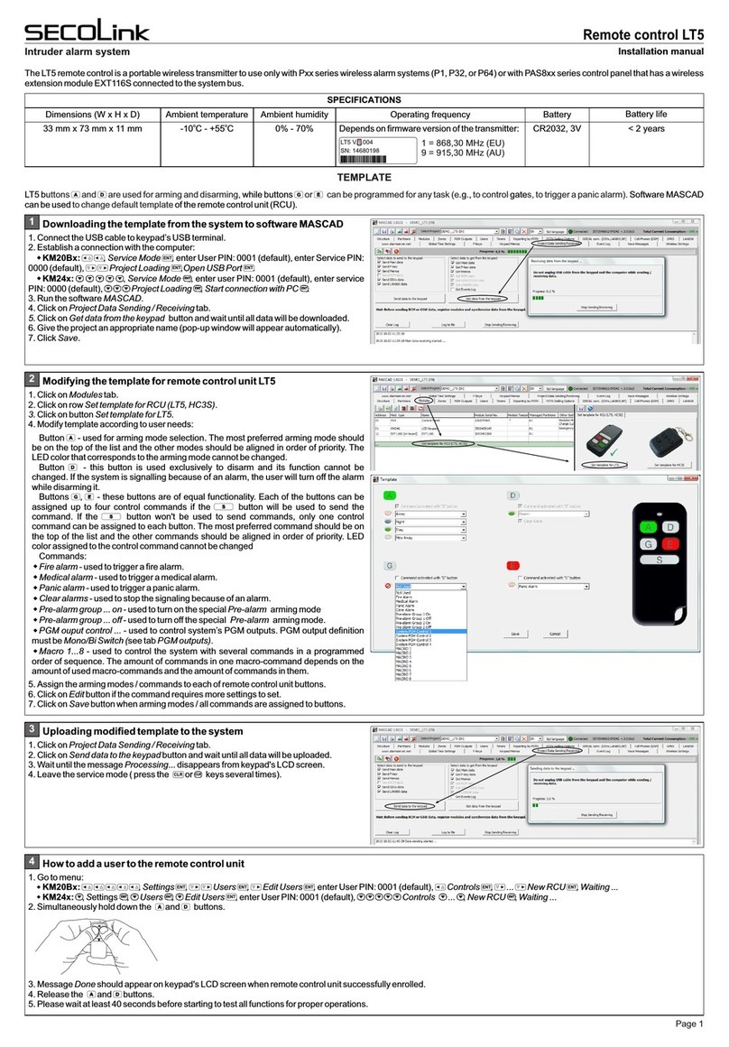
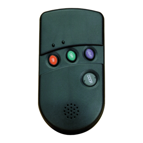
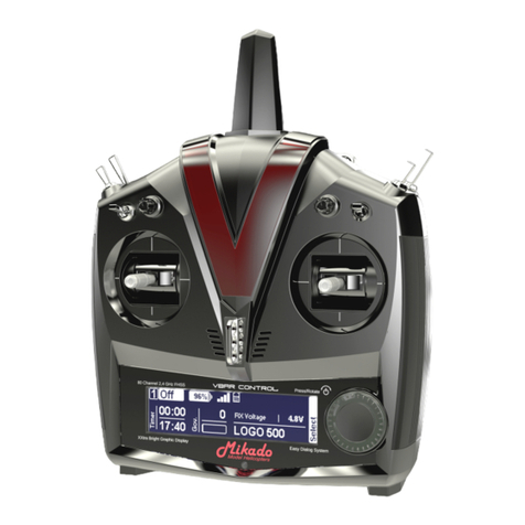
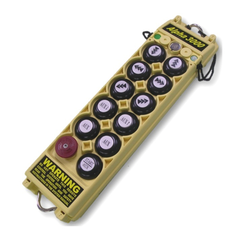
SECOLink LT5 User manual

Remote control LT5
Intruder alarm system User manual
GENERAL INFORMATION
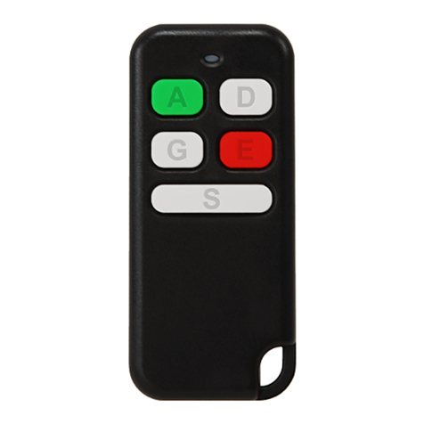
Button -thisbuttonisusedforarmingmodeselection.Armingmodesallignedbypriority:
1stposition =Away(color:Red);
2ndposition=Night(color:Blue);
3rdposition =Stay(color:Green);
4thposition =MaxAway(color:White).
Button -thisbuttonisused exclusivelytodisarm.Ifthesystemissignallingbecauseof analarm,theuserwill
turnoffthealarmalongwithdisarming.
Button -thisbuttonisusedtoclearalarmwithasinglepress.
Button - this button is used to trigger panic alarm. To avoid false panic alarms, the button must be
pressed.
LT5buttons and aretypicallyused forarminganddisarming,then or buttonscanbe programmedfor
any task (ex. to control gates, to trigger a panic alarm).A button must be pressed as many as needed until the
required color light, that corresponds arming mode / programmed command, appears on LED. The button
is used to send a selected arming mode / command to receiver. The pressing of it minimizes the possibility of
accidentaltransmissions.Itisalsousedtogetastatusofthesystem.
Thefactoryprogrammedremotecontrolunit(RCU)template:
Remote control LT5
ASSIGNING A REMOTE CONTROL UNIT TO THE USER
ARMING
REMOVING A REMOTE CONTROL UNIT FROM THE USER
Simultaneosly hold down the buttons
and .
1111
MainMenu MainMenu
Settings Settings
2222
2222
Settings Settings
Users Users
Users Users
Edit users Edit users
U01 User 01 U01 User 01
Controls Controls
NewRCU RemoveRCU
6666
Waiting... Waiting...
Done Message Done should appear on
keypad LCD when remote control unit is
enrolled succesfully. Release buttons
and .
Done Message Done should appear on
keypad LCD when all remote control unit
areremovedfromtheuser.
Advance to the next user with a keypad
keys or .
7
PQRS
7
PQRS
7
PQRS
7
PQRS
7
PQRS
7
PQRS
7
PQRS
7
PQRS
7
PQRS
7
PQRS
7
PQRS
Advance to the next user with a keypad
keys or .
7
PQRS
7
PQRS
7
PQRS
7
PQRS
7
PQRS
7
PQRS
7
PQRS
7
PQRS
7
PQRS
7
PQRS
7
PQRS
In menu bar choose New RCU and press
button.ENTENTENTENTENTENTENTENTENTENTENT
ChooseNewRCUandpress button.
ENTENTENTENTENTENTENTENTENTENTENT Choose Remove RCU and press
button.ENTENTENTENTENTENTENTENTENTENTENT
U01 User 01 U01 User 01
Name Name
User 01 User 01
1111
ArminginAwaymode:
Press the button while the
Red color light is visible on LED (it
will last ~3 sec after the button is
pressed) and wait answer from the
system.
Press the button as many times as
needed until the Red color light appears
on LED and then release the button.
Red =Away
If the system is succesfully armed in Away mode the answer from the
system will be long Red color flash on LED.
RB
G
WR
B
GWDuration: ~3 sec
RRed(long: ~1 sec) = system is
armedinAwaymode
No flash = no answer from the
system!
Green (short: ~0,1sec) = battery
isgood
Red(short)=batteryislow
Answer from the
system
GR
G
R
R
Command sending and
battery status indication
Page 1

Remote control LT5
Intruder alarm system User manual
ARMING (CONTINUED)
DISARMING
ArminginNightmode:
ArminginStaymode:
Press the button while the
Blue color light is visible on LED
and wait answer from the system.
Press the button while the
Green color light is visible on LED
and wait answer from the system.
Press the button as many times as
needed until the Blue color light appears
on LED and then release the button.
Press the button as many times as
needed until the Green color light
appears on LED and then release the
button.
Green = Stay
Blue = Night
If the system is succesfully armed in Night mode the answer from the
system will be long Blue color flash on LED.
If the system is succesfully armed in Stay mode the answer from the
system will be long Green color flash on LED.
R
R
B
B
G
G
W
W
R
R
B
B
G
G
W
W
B
G
Blue (long) = system is armed
inNightmode
Green (long) = system is
armedinStaymode
No flash = no answer from the
system!
No flash = no answer from the
system!
Answer from the
system
Answer from the
system
G
G
B
G
B
G
ArminginMaxAwaymode:
Press the button while the
White color light is visible on LED
and wait answer from the system.
Press the button while the
Green color light is visible on LED
and wait answer from the system.
Press the button as many times as
needed until the White color light
appears on LED and then release the
button.
Press the button. The Green light
appears on LED.
White =Max Away
If the system is succesfully armed in Max Away mode the answer from
the system will be long White color flash on LED.
If the system is successfully disarmed the answer from the system will
be short Green color flash on LED.
RB
G
WR
B
GW
WWhite (long) = system is
armedinMaxAwaymode
No flash = no answer from the
system!
Answer from the
system
GWW
GGreen (short) = system is
disarmed.
No flash = no answer from the
system!
Answer from the
system
If the system is successfully disarmed the answer from the system will be
short Green color flash on LED.
Press the button while the colored
light is visible on LED.
Press the button. The Green light
appears on LED. G
GGreen (short) = system is
disarmed.
No flash = No answer from the
system! Go closer to the
receiver.
Answer from the
system
G
G
G
G
G
Page 2

Remote control LT5
Intruder alarm system Installation manual
STATUS INQUIRY
ALARM CLEARING WITH BUTTON (SINGLE PRESS OPERATION)
TRIGGERING PANIC ALARM WITH BUTTON. COMMAND SENDING WITH PRESSING THE BUTTON
BATTERY REPLACEMENT
The answer from the system depends on system status (see picture).
Press the button.
GR
Red (short) = PGM output is turned Off
Red (long) = command is executed /PGM output is turned
No flash = No answer from the system!
B
R
R
If the command is executed / PGM output is turned On the answer from the system will be long Red color
flash. If the PGM output is turned Off the answer from the system will be short Red color flash.
Green(short:~0,1sec)=batteryisgood
Red(short)=batteryislow
Answer from the
system
G?
G
R
Command sending and
battery status indication
Green (short: ~0,1 sec) = system is disarmed
Red (long: ~1 sec) = system is armed in Away mode
Blue (long) = system is armed in Night mode
Green (long) = system is armed in Stay mode
White (long) = system is armed in Max Away mode
No flash = No answer from the system!
B
R
G
W
G
Press the button while the
Red color light is visible on LED
and wait answer from the system.
Only one command is assigned to
button in default project. This is the
reason why only Red color light will be
visible on LED.
If the panic alarm is succesfully triggered the answer from the system
will be long Red color flash on LED.
RRed (long) = panic alarm is
triggered
No flash = no answer from the
system!
Answer from the
system
GRR
Red =Panic
Green = Not Used
Blue = Not Used
White = Not Used
RB
G
WR
B
GW
Pleaseactaccordingtolocallaws.Don'tthrowawayunusablealarmsystemsorit'scomponentsalongwithhouseholdwaste.
ThisproductsutilizationinEUstatesisregualtedbyEUdirective2002/96/EC
Batteryintheremotecontrolunitlifetimedependingontheenvironment,usageandthespecificwirelessdevicebeingused.Factorssuchashumidity,high
or low temperatures, as well as large swings in temperature may all reduce the actual battery life.When the battery is nearly dead, the remote control unit
showsthatwiththeLED.ItisshowingthebatterystatusonLEDwhenitissendingacommandtoreceiver.
BATTERY REPLACEMENT
Insert the blade of a small
screwdriver between the remote
control unit plastic top and bottom
cover and slightly turn it.
Remove the screw that is holding
the electronic circuit board in place. Insert the blade of a small
screwdriver in place as it is shown in
picture and carefully remove the
electronic circuit board from plastic
housing.
Use an isolated stick and remove the old battery.
With a positive (+) end of a new battery facing UP,
insert the new battery as shown in picture.
New battery
2
1
Old battery
Press the button.
Page 3
Rev.01/02/16
Other SECOLink Remote Control manuals
