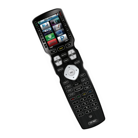
SECOLink LT5 User manual

TheLT5remotecontrolisportablewirelesstransmitterforuseonlywithPxxserieswirelessalarmsystems(P16,P32orP64)orwithPAS8xxseriescontrolpanelthathaswireless
extensionmoduleEXT116Sconnectedtothesystembus.
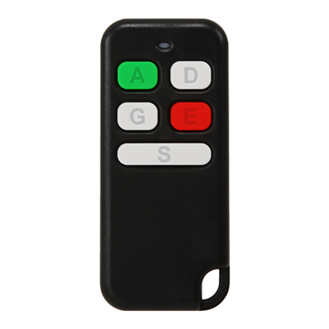
Remote control LT5
Intruder alarm system Installation manual
LT5 > 3years
SPECIFICATIONS
Dimensions (W x H x D) Ambient humidityAmbient temperature Battery Battery lifetime
33 mm x 73 mm x 11 mm oo
-10 C - +55 C 0% - 70% Dependsonfirmwareversionofthetransmitter: CR2032, 3V
Operating frequency
1 = 868,30 MHz (EU)
9= 915,30 MHz (AU)
LT5b gate
remotecontrolunit(RCU) canbedonewithasoftwareMASCAD.
uttons and aretypically usedfor armingand disarming,then or buttons canbe programmedfor any task(ex. tocontrol s,to triggera panicalarm).In orderto
changethedefault templateit
TEMPLATE
1DownloadingthetemplatefromthesystemtosoftwareMASCAD
2
1.ConnectUSBcabletokeypadUSBterminal.
2.Establishtheconnectionwithacomputer:
KM20Bx: ,ServiceMode ,enterUserPIN:0001(default),enterServicePIN:
0000(default), ProjectLoading ,OpenUSBPort .
KM24x: , Service Mode , enter user PIN: 0001 (default), enter service
PIN:0000(default), ProjectLoading ,StartconnectionwithPC .
3.RunthethesoftwareMASCAD.
4.ClickontabProjectDataSending/Receiving.
5.ClickonthebuttonGetdatafromthekeypadandwaituntilalldatawillbedownloaded.
6.Giveareasonablenametotheproject(popupwindowwillappearautomaticaly).
7.ClickonbuttonSave.
ENT
ENT ENT
ENTENTENTENT
ENTENTENTENT ENTENTENTENT
1.ClickontabModules.
2.ClickonrowSettemplateforRCU(LT5,HC3S).
3.ClickonbuttonSettemplateforLT5.
4.Modifytemplateaccordinguserneeds:
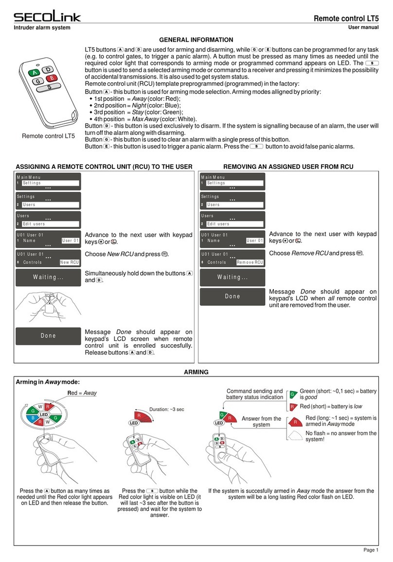
Button - used for arming mode selection. The most preferred arming mode should
be on the top of the list, and the other modes should be aligned in order of priority. The
LEDcolorthatcorrespondsthearmingmodecannotbechanged.
Button -this buttonisused exclusivelyto disarm,it'sfunction cannotbe changed.If
the system is signalling because of an alarm, the user will turn off the alarm along with
disarming.
Buttons , - these buttons are of equal functionality. Each of the buttons can be
assigned up to four control commands if the button will be used to send the
command. If the button for sending the command wont be used, only one control
command can be assigned to it. The most preferred command should be on the top of
the list, and the other commands should be alignet in order of priority. The LED color
assignedtothecontrolcommandcannotbechanged.
Commands:
Firealarm-usedtotriggerafirealarm.
Medicalalarm-usedtotriggeramedicalalarm.
Panicalarm-usedtotriggerapanicalarm.
Clearalarms-usedtostopthesignalingbecauseofanalarm.
Pre-alarmgroup...on-usedtoturnonthespecialarmingmodePre-alarm.
Pre-alarmgroup...off-usedtoturnoffthespecialarmingmodePre-alarm.
PGMouputcontrol...-usedtocontrolthesystemPGMoutputs.PGMoutputdefinition
mustbeMono/BiSwitch(seetabPGMoutputs).
Macro1...8 - usedtocontrol thesystemwith severalcommandsin programmedorder
of sequence. The amount of commands in one macro-command depends on the
amountofusedmacro-commandsandtheamountofcommandsinthem.
5.Assignthearmingmodes/commandstoeachofremotecontrolunitbuttons.
6.ClickonEditbuttonifthecommandrequiresmoresettingstoset.
7.ClickonbuttonSavewhenarmingmodes/allcommandsareassignedtobuttons.
3
1.ClickontabProjectDataSending/Receiving.
2.ClickonthebuttonSenddatatothekeypadandwaituntilalldatawillbeuploaded.
3.TakealookonkeypadLCDscreen.WaituntilthemessageProcessing...disapears.
4.Leavetheservicemode(severaltimespresskeys or ).
CLR
CLRCLRCLRCLR
ModifyingthetemplateforremotecontrolunitLT5
Uploadingthemodifiedtemplatetothesystem
4Assigningtheremotecontrolunit totheuser
1.Gotomenu:
KM20Bx: ,Settings , Users , EditUsers ,enterUserPIN:0001(default), Controls , ... NewRCU ,Waiting...
KM24x: ,Settings , Users , EditUsers ,enterUserPIN:0001(default), Controls ... ,NewRCU ,Waiting...
2.Simultaneoslyholddownthebuttons and .
ENT ENT ENT ENT ENT
ENTENTENTENT ENTENTENTENT
ENT
ENTENTENTENT
3.MessageDoneshouldappearonkeypadLCDwhenremotecontrolunitisenrolledsuccesfully.
4.Releasebuttons and .
5.Pleasewaitatleast40secondsbeforestartingtotestallfunctionsforproperoperations.
Page 1

Remote control LT5
Intruder alarm system Installation manual
Arming
1
Disarming
Statusinquiry
If the system is successfully disarmed the answer from the system will be
short Green color flash on LED.
GGGreen (short) = system is
disarmed.
No flash = No answer from the
system! Go closer to the
receiver.
Answer from the
system
G
G
Press the button while the colored
light is visible on LED.
Press the button. The Green light
appears on LED.
The answer from the system depends on system status (see picture).
Answer from the
system
Press the button.
Green (short) = system is disarmed.
Red (long) = system is armed in Away mode
Blue (long) = system is armed in Night mode
Green (long) = system is armed in Stay mode
White (long) = system is armed in Max Away mode
No flash = No answer from the system! Go closer to
the receiver.
B
R
G
W
G
Duration: ~3 sec
Press the button as many times as
needed until the Red color light appears on
LED (see picture) and then release the
button.
Red =Away
Green = Stay
Blue = Night
White =Max Away
If the system is succesfully armed in Away mode the answer from the system
will be long Red color flash on LED.
Red (long) = system is armed
in Away mode
No flash = no answer from
the system! Go closer to the
receiver.
Green (short) = battery is good
Red (short) = battery is low
Answer from the
system
(duration: ~1 sec)
RB
G
WR
B
GW
RGR
G
R
R
Press the button while the Red color
light is visible on LED (it will last ~3 sec
after the button is pressed) and wait answer
from the system.
Note: thisexample showshow toarm thesystem inAwayarming mode.Thisarming modeis representedby Redcolor lighton LEDat the armingmode selectionwhile pressing
the button.Armingmodesalignedbypriority:1.Away(Red);2.Night(Blue);3.Stay(Green);4.MaxAway(White).
Command sending and
battery status indication
(duration: ~0,1 sec)
EXAMPLES OF USE
2
3
BATTERY REPLACEMENT
Pleaseactaccordingtolocallaws.Don'tthrowawayunusablealarmsystemsorit'scomponentsalongwithhouseholdwaste.
ThisproductsutilizationinEUstatesisregualtedbyEUdirective2002/96/EC
Batteryintheremotecontrolunitlifetime depending ontheenvironment, usage andthe specificwirelessdevice being used.Factorssuch as humidity,highorlowtemperatures,
as well as large swings in temperature may all reduce the actual battery life.When the battery is nearly dead, the remote control unit shows that with the LED. It is showing the
batterystatusonLEDwhenitissendingacommandtoreceiver.
New battery
2
1
Old battery
Page 2Rev.01/02/16
Other SECOLink Remote Control manuals
