Sectoriel 736 XS Quick guide

736-746XS VALVE WITH SF SWITCH BOX
Information given as an indication only, and subject to possible modifications
SECTORIEL S.A.
45 rue du Ruisseau
38290 SAINT QUENTIN-FALLAVIER –FRA NCE
Telephone: +33 4 74 94 90 70 - Fax: +33 4 74 94 13 95
www.sectoriel.fr / Email : sectoriel@sectoriel.fr
Pages
1/6
Ref.
FT746XS+SF ENG
Rev.
03
Date
06/2020
FEATURES
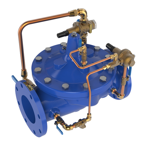
The 2-way 736 XS (steel) or 746 XS (stainless steel) ball valve + SF is intended for the manual shut-off of networks
for industrial fluids, providing position display and feedback information control. This 3-piece external tie-bolt
ball valve is easy to remove for servicing. This full-bore valve has an anti-static device and double leak-proofing
at the cable gland. It is EC- and ATEX- and TA-LUFT-approved. The SF switch box is equipped, as standard, with 2
dry contacts. Due to its IP67 leak-tightness, it can be installed both indoors and outdoors. Different contacts and
detectors are available as options.
AVAILABLE MODELS
1/4’’ to 4’’ diameters
Electrical connection: 2 x M20x1.5
Connection
G
SW
BW
steel
736 XS
735 XS
734 XS
stainless steel
746 XS
743 XS
745 XS
LIMITS OF USE
Material
steel
stainless steel
Fluid pressure: WP
63 bar (20°C)
Fluid temperature: WT°
-25°C / +180°C
- 40°C / +180°C
Ambient temperature
- 20°C / + 80°C
IP Code
IP 67
DIRECTIVES AND MANUFACTURING STANDARDS
OBJECT
Standard
ON
OBJECT
Standard
Pressure Equipment Directive
2014/68/EC
1/4” to 1”: not subject
Final test
EN 12266
1’’ 1/4 to 4’’: category III
TÜV 0035
Material certificate
EN 10204
ATEX Directive
II 2G/D Tx zones 1,2,21 and 22
SIRA 0518
Size
EN 12516-1
EN 13463-1 and 5
Steel grades
EN 1503-1
3.1
Cert.
0035
ISO
9001
TA
LUF
0
10
20
30
40
50
60
70
80
-40 -20 0 20 40 60 80 100 120 140 160 180
Pressure (bar)
Temperature (°C)
Operation range for
stainless steel
Operation range for steel

736-746XS VALVE WITH SF SWITCH BOX
Information given as an indication only, and subject to possible modifications
SECTORIEL S.A.
45 rue du Ruisseau
38290 SAINT QUENTIN-FALLAVIER –FRA NCE
Telephone: +33 4 74 94 90 70 - Fax: +33 4 74 94 13 95
www.sectoriel.fr / Email : sectoriel@sectoriel.fr
Pages
2/6
Ref.
FT746XS+SF ENG
Rev.
03
Date
06/2020
CONSTRUCTION
No.
Name
Steel
Stainless steel
No.
Name
Steel
Stainless steel
1
Body
1.0619
1.4408
12
Nut
304 SS
304 SS
2
Ends
1.0619
1.4408
13
Stop
304 SS
304 SS
3*
Seats
PTFE+15%GF
PTFE+15%GF
14
Coupling
PVC
PVC
4
Sphere
CF8M / 316
CF8M / 316
15
Tie-bolts
304 SS
304 SS
5
Stem
316 SS
316 SS
16
Washer
304 SS
304 SS
6*
Body gasket
PTFE
PTFE
17
Nuts
304 SS
304 SS
7*
Washer
PTFE+15%GF
PTFE+15%GF
18*
O-ring
FPM
FPM
8*
Gasket
PTFE
PTFE
19
Tab washer
304 SS
304 SS
9
Spacer
304 SS
304 SS
20
Anti-static
316 SS
316 SS
10
B. washer
301 SS
301 SS
21
Spring
304 SS
304 SS
11
Lever
304 SS
304 SS
* Parts included in the maintenance kit
DIMENSIONS (mm)
DN
A
B
(G)
B
(SW)
B1
(BW)
C
D
E
F
F1
G
H
J1
SW
1/4’’
10
65
65
70
46.5
110
14
13
17.0
26.0
41.0
42
9
3/8’’
12.5
65
65
70
46.5
110
14
13
17.0
24.5
42.3
42
9
1/2’’
16
75
75
75
70.9
110
21.9
17
22.4
25.2
42.3
42
9
3/4’’
20
80
80
90
73.4
110
27.2
22
28.2
27.7
44.8
42
9
1’’
24.5
90
90
100
84.1
135
34.0
28
33.7
33.0
54.0
50
11
1’’ 1/4
32
110
110
110
89.3
135
42.7
37
44.0
41.2
59.2
50
11
1’’ 1/2
38
120
120
125
109.5
165
48.8
43
50.8
49.3
73.5
70
14
2’’
50
140
140
150
118.9
165
61.3
54
62.6
63.6
82.9
70
14
2’’ 1/2
65
185
185
190
155.0
300
77.0
74
76.1
82.1
107.0
102
17
3’’
80
205
205
220
165.0
335
90.0
83
88.9
95.8
117.3
102
17
4’’
100
240
240
270
180.0
335
115.5
110
114.3
117.8
132.3
102
17

736-746XS VALVE WITH SF SWITCH BOX
Information given as an indication only, and subject to possible modifications
SECTORIEL S.A.
45 rue du Ruisseau
38290 SAINT QUENTIN-FALLAVIER –FRA NCE
Telephone: +33 4 74 94 90 70 - Fax: +33 4 74 94 13 95
www.sectoriel.fr / Email : sectoriel@sectoriel.fr
Pages
3/6
Ref.
FT746XS+SF ENG
Rev.
03
Date
06/2020
ASSEMBLY AND MAINTAINANCE INSTRUCTIONS
1 - Installation
1.1 - Checks
oCheck that the material of the valve body is chemically compatible with the fluid.
oCheck that the pressure and service conditions are compatible with the (P, T) diagram of the valve. See
§ “Service limits”
oCheck that the fluid is clean and free of particles. The latter could scratch the ball and damage the seats,
hence causing the valve to leak. If need be, install an upstream filter.
oCheck that there is no risk of thermal expansion of the fluid, which could damage the seats. In the open
position, a hole at the top of the ball balances the pressures between the body cavity and the flow of
the fluid. As an option, we recommend a relief hole upstream of the valve for balancing the pressures
for fluids such as ammonia, LPG, chlorine, etc.
oCheck that the valve is not used for flow or pressure control since it is not intended for this use and
there is a risk of premature wear of the seats, in particular in the event of high pressure and/or
temperature. For this special application, preferably use our ‘”V-port” version with a V-shaped hole in
the ball. Please contact us.
oCheck that the valve is not used on a gas which might condense at certain times during the process. In
such a case, the pressure within the body cavity could become negative, which could lead to a significant
deformation of the seats. Please contact us.
oStatic electricity: the valve will be supplied with a ball-stem-body internal electrical continuity tester. If
the service conditions require the electrical continuity of the installation, check its earthing.
oIf the valve is installed in an explosive zone, you must follow the additional “IMEVMATEX” instructions.
1.2 - Storage before installation
oFollow our general “IMESTOCK” instructions for storage.
oCheck that the tie-bolts of the valves were not loosen during transport.
1.3 - Installation
oBefore any installation, isolate the piping upstream and downstream, depressurize the piping and bring
the installation to ambient temperature. Carefully clean the piping of any particle (foreign body, dust,
rust, etc.) or shavings by water rinsing or air blowing.
oFor valves with a size above DN50, plan to use a hoist.
oRemove the protective tips from the valve ends.
oCheck the cleanliness of the internal surfaces of the valve and if need be, clean them.
oDirection of mounting: the valves do not have a preferred direction of mounting, unless a relief hole
was drilled into the ball.
oCheck the perfect alignment and the proper support of the pipe installation upstream and downstream
of the valve. Alignment defects cause mechanical deformations which can block the valve or lead to
leaks at the body gaskets.

736-746XS VALVE WITH SF SWITCH BOX
Information given as an indication only, and subject to possible modifications
SECTORIEL S.A.
45 rue du Ruisseau
38290 SAINT QUENTIN-FALLAVIER –FRA NCE
Telephone: +33 4 74 94 90 70 - Fax: +33 4 74 94 13 95
www.sectoriel.fr / Email : sectoriel@sectoriel.fr
Pages
4/6
Ref.
FT746XS+SF ENG
Rev.
03
Date
06/2020
oThreaded valve connection:
oCheck that the standards for the valve internal thread and pipe thread are the same.
oCover the pipe threads using a sealing material (tow, PTFE tape, sealing glue, etc.) which is
suitable for the fluid.
oScrew the tube into the valve end clockwise, as shown in the diagram below.
oCheck the sealing of the connection using a suitable test (hydrostatic test or leak detection
spray).
oConnection of weld-on valves:
oRemove the end (items 2) by unscrewing the tie-bolts, and remove the central body.
oWeld each end onto the upstream or downstream pipe, following the alignment of the tie-bolt
holes.
oCool down to the room temperature the welded ends, then put back the central body
complying with the tightening torques shown in the table below.
oCheck the sealing of the connection using a suitable test (hydrostatic test or leak detection
spray).

736-746XS VALVE WITH SF SWITCH BOX
Information given as an indication only, and subject to possible modifications
SECTORIEL S.A.
45 rue du Ruisseau
38290 SAINT QUENTIN-FALLAVIER –FRA NCE
Telephone: +33 4 74 94 90 70 - Fax: +33 4 74 94 13 95
www.sectoriel.fr / Email : sectoriel@sectoriel.fr
Pages
5/6
Ref.
FT746XS+SF ENG
Rev.
03
Date
06/2020
oHydraulic test of the installation
oValves were tested at the factory at 1.5 x WP.
oIf a hydrostatic test is carried out on the installation, do not exceed the authorised pressure.
2 - Service
oIf a hot fluid flows across the valve, do not touch the valve surface.
oAlways operate the valve slowly and smoothly.
oOpening clockwise, closing anti-clockwise.
3 - Servicing
3.1 - Frequency of servicing
oThe servicing frequency depends upon the use of the valve, of the type of fluid, of its velocity, of its
frequency of operation, of the cycles of rise and fall in pressure and temperature.
oBefore any intervention, isolate the upstream and downstream pipe installation using the valves
provided for this purpose. Depressurize the pipe installation and bring it to ambient temperature.
oIf the lever has to be removed, do that before disassembling the body.
oTo remove the central body, unscrew the tie-bolts symmetrically. Then gently remove the central part
avoiding to drop the ball.
oTo remove the ball from the body, turn the stem by a quarter turn.

736-746XS VALVE WITH SF SWITCH BOX
Information given as an indication only, and subject to possible modifications
SECTORIEL S.A.
45 rue du Ruisseau
38290 SAINT QUENTIN-FALLAVIER –FRA NCE
Telephone: +33 4 74 94 90 70 - Fax: +33 4 74 94 13 95
www.sectoriel.fr / Email : sectoriel@sectoriel.fr
Pages
6/6
Ref.
FT746XS+SF ENG
Rev.
03
Date
06/2020
3.2 –Inspecting the state of the valve and possible repair
oCheck the state of the ball (Item 4): it has to be clean and unscratched. If the cleaning or polishing is not
possible, replace it (see the § on spare parts).
oCheck the state of the seats (3.1 and 3.2): they must not be deformed, nor scratched, nor worn, or dirty.
Otherwise, replace them with parts from the gasket kit.
oCheck the state of the packing gland (7.8 and 9): no leak should be found at the stem and the rings
should not be excessively worn. If need be, replace the gaskets.
oCheck the state of the body gaskets (6.1 and 6.2). Replace them if necessary.
oReassemble the different parts of the valve, following the tightening torques shown in the table below.
oCheck that the stem manoeuvring is smooth. Perform about ten manoeuvres.
TABLE OF THE TIGHTENING TORQUES OF THE TIE-BOLTS AND OF THE LEVER NUT
DN
Tie-bolts
Torque (Nm)
Lever nut (Nm)
1/4’’ - 6
M6
190
4
3/8’’ - 10
M6
190
4
1/2’’ - 15
M6
190
4
3/4’’ - 20
M8
220
4
1’’ - 25
M8
250
4.5
1’’1/4 - 32
M10
310
4.5
1’’1/2 - 40
M10
410
5.5
2’’ - 50
M10
410
5.5
2’’1/2 - 65
M12
1000
7
3’’ - 80
M16
1220
7
4 ‘’ - 100
M16
1430
7
SPARE PARTS
DN
Gasket kit
Ball
V30° ball
V60° ball
Tie-bolt kit
Lever
Reference mark
3-6-7-8-18
4
4
4
15-16-17
11
1/4’’ - 6
Please contact
us.
Please
contact us.
Please
contact us.
Please
contact us.
Please
contact us.
Please
contact us.
3/8’’ - 10
Please contact
us.
Please
contact us.
Please
contact us.
Please
contact us.
Please
contact us.
Please
contact us.
1/2’’ - 15
982852
980032
980042
980052
982832
982802
3/4’’ - 20
982853
980033
980043
980053
982833
982802
1’’ - 25
982854
980034
980044
980054
982834
982804
1’’1/4 - 32
982855
980035
980045
980055
982835
982804
1’’1/2 - 40
982856
980036
980046
980056
982836
982806
2’’ - 50
982857
980037
980047
980057
982837
982806
2’’1/2 - 65
982858
Please
contact us.
Please
contact us.
Please
contact us.
982838
982808
3’’ - 80
982859
Please
contact us.
Please
contact us.
Please
contact us.
Please
contact us.
982808
4 ‘’ - 100
982860
Please
contact us.
Please
contact us.
Please
contact us.
Please
contact us.
982808


SF-TYPE SOLDO SWITCH BOXES
Information given as an indication only, and subject to possible modifications
SECTORIEL S.A.
45 rue du Ruisseau
38290 SAINT QUENTIN-FALLAVIER –FRANCE
Tél : +33 4 74 94 90 70 –Fax : +33 4 74 94 13 95
www.sectoriel.fr / Email : sectoriel@sectoriel.fr
Pages
1/3
Ref.
FT4620 ENG
Rev.
04
Date
04/2017
FEATURES
The SF-type switch box is intended for equipping quarter-turn pneumatic actuators and manual valves. It makes
it possible to have an easy, direct view of the valve position and of the feedback information to control. Of robust
construction, it can be installed outdoors. The position indicator provides a very good visual reading of the valve
position. The SF switch box can be equipped with many switches and detectors (see below). The notched cams
can be manually adjusted with great accuracy, and are insensitive to vibrations.
AVAILABLE MODELS
SF: IP67 model
LIMITS OF USE
Ambiant temperature
-20°C / +80°C
IP Code
IP 67
SF
Outiside ATEX zone
MECHANICAL CONNECTION
Axis dimension
According to VDI/VDE 3845
Attachment
ISO 5211 F05
Stainless steel arches for
attachment on to the
actuator
NAMUR 0 : 50x25x20 mm
NAMUR 1 : 80x30x20 mm
NAMUR 2 : 80x30x30 mm
NAMUR 3 : 130x30x30 mm
NAMUR 4 : 130x30x50 mm
ELECTRICAL CONNECTION
Standard cable inputs
2 x M20x1.5
CONSTRUCTION
Casing and lid
Aluminium
Coating
Polyester paint
Stem
Stainless steel
Dome
Polycarbonate
IP
67
ISO
9001

SF-TYPE SOLDO SWITCH BOXES
Information given as an indication only, and subject to possible modifications
SECTORIEL S.A.
45 rue du Ruisseau
38290 SAINT QUENTIN-FALLAVIER –FRANCE
Tél : +33 4 74 94 90 70 –Fax : +33 4 74 94 13 95
www.sectoriel.fr / Email : sectoriel@sectoriel.fr
Pages
2/3
Ref.
FT4620 ENG
Rev.
04
Date
04/2017
SWITCH DETAILS SF model
Ref.
Switch
Features
01
SPDT el.mech. switch silver plated contacts
Max 5A-250Vac / min 50mA-250Vac
Max 5A-125Vac / min 50mA-125Vac
Max 3A-24Vdc / min 50mA-24Vdc
03
SPDT el.mech. switch gold plated contacts (for Exia cert)
Max 1,8A/3A-250Vac / min 5mA-250Vac
Max 2A/3A-125ac / min 5mA-125Vac
Max 1,2A/1,5A-24Vdc / min 1mA-24Vdc
1F
DPDT el.mech. switch silver plated contacts
C4
SPDT magnetic hermetically sealed reed switch.
Max 0,1A-120Vac / 1A-24Vdc
C8
DPDT magnetic hermetically sealed reed switch.
Max 0,1A-120Vac / 1A-24Vdc
N1
SPDT magnetic hermetically sealed silver plated snap acting contacts
Max 5A-250Vac / 5A-28Vdc
N3
SPDT magnetic hermetically sealed gold plated snap acting contacts
Max 1A-250Vac / 1A-30Vdc
N4
DPDT magnetic hermetically sealed silver plated snap acting contacts
Max 5A-250Vac / 5A-28Vdc
60
Inductive proximity NAMUR sensor SJ3,5-N
2 wire NC logic (for Exia cert)
62
Inductive proximity NAMUR sensor SJ3,5-SN
2 wire NC logic (for Exia cert, safety funct. low temp)
63
Inductive proximity NAMUR sensor - SJ3,5-S1N
2 wire NO logic (for Exia cert, safety funct)
70
Inductive proximity NAMUR - NJ2-V3-N
2 wire (for Exia cert)
73
Inductive proximity sensor (+70°C max.) - NBB2-V3-E2
P+F - 3 wire PNP NO amplified 10-30 Vdc, 100 mA
75
Inductive proximity sensor - IS 5026
IFM - 2 wire NO/NC amplified 5-36 Vdc, 200 mA
83
Inductive proximity sensor - NBB3-V3-Z4
P+F - 2 wire NO amplified 5-60 Vdc, 100 mA
TO
4-20 mA position transmitter
12-30 Vdc
HO
4-20 mA HART position transmitter
Atex Ex ia IIC T6 / T4 –certified 8-30Vdc
OPTIONS
There are many options for which you are invited to contact our sales service:
SS : stainless steel box
3-Channel L or T indicators
L
LT : version -40°C (according to the type of switch)
P
LT 1 : version -55°C (according to the type of switch)
1
Cable inputs 1/2" NPT
Pilot-solenoid valve wiring
G
EAC Certificate
U
UL Certificate

SF-TYPE SOLDO SWITCH BOXES
Information given as an indication only, and subject to possible modifications
SECTORIEL S.A.
45 rue du Ruisseau
38290 SAINT QUENTIN-FALLAVIER –FRANCE
Tél : +33 4 74 94 90 70 –Fax : +33 4 74 94 13 95
www.sectoriel.fr / Email : sectoriel@sectoriel.fr
Pages
3/3
Ref.
FT4620 ENG
Rev.
04
Date
04/2017
DIMENSIONS (mm)
This manual suits for next models
5
Table of contents
Other Sectoriel Control Unit manuals
Popular Control Unit manuals by other brands

Sony
Sony Ipela Quick reference guide

Siemens
Siemens SINUMERIK 840D sl Commissioning manual
Franke
Franke DVS AC17-080 Installation & operating instructions

Intermatic
Intermatic ET9232 Replacement instructions
Villeroy & Boch
Villeroy & Boch Heating Control Start-up and operation
Polycom
Polycom RMX DOC2560B Getting started guide


