Ventus VS 10-75 CG OPTIMA User manual

Compact control gear for Supply
and Supply-Exhaust Air Handling Units
VS 10-75 CG OPTIMA
VS 40-150 CG OPTIMA SUP
VS 40-150 CG OPTIMA SUP-EXH
Operation and Maintenance Manual
EN
DTR-CG OPTIMA – ver.2.0 (05.2012)

www.vtsgroup.com
Control boxes VS 10-75 CG OPTIMA; VS 40-150 CG OPTIMA SUP; VS 40-150 CG OPTIMA
SUP-EXH are designed according to the following European standards: EN 60335-1; EN
60439-1; EN 60439-3; EN 50082-1; EN 50081-1
EN

EN
VTS reserves the right to implement changes without prior notice
User’s Manual 1
Table of Content
USER’S MANUAL................................................................................................ 3
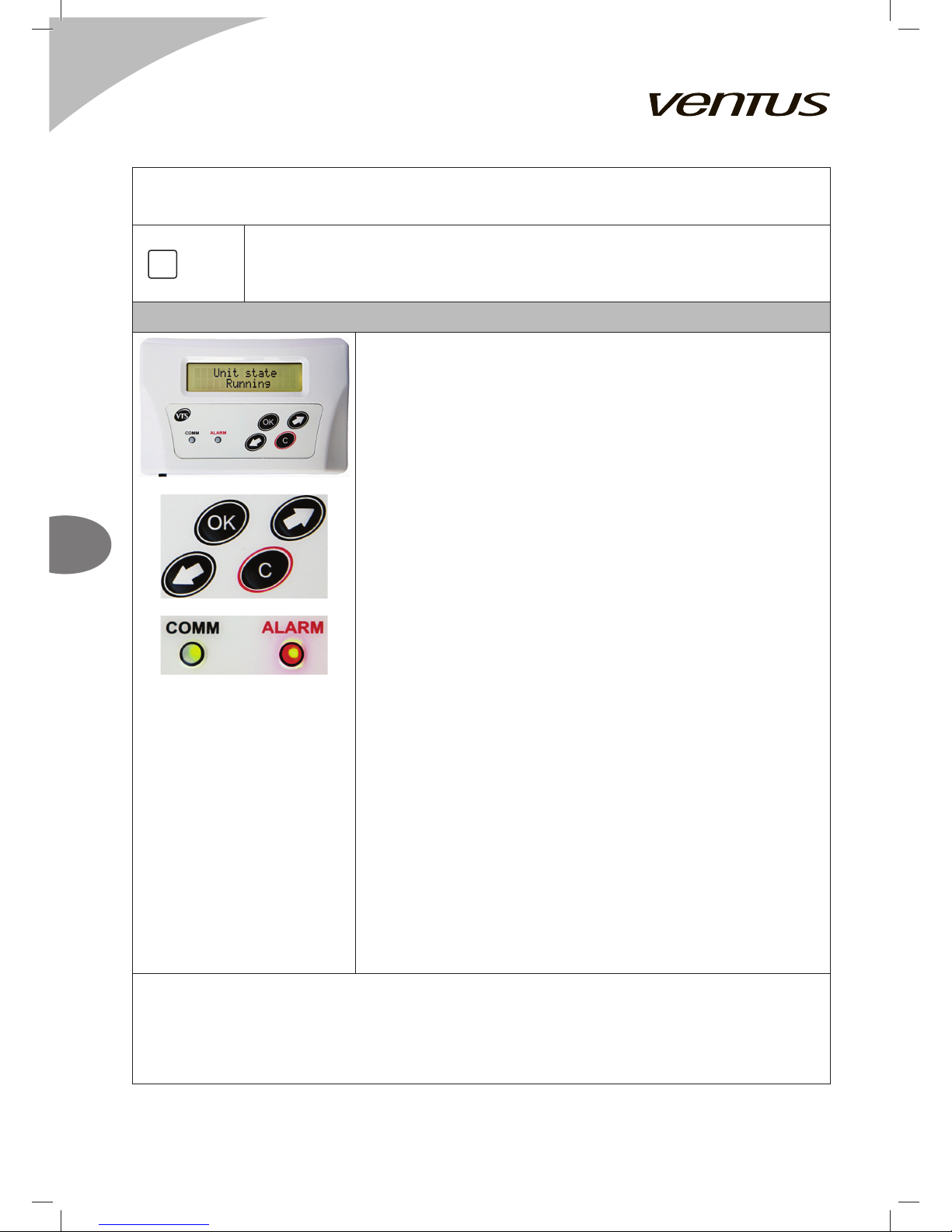
1. DESCRIPTION OF CONTROLS ............................................................................................................................................ 3
INTRODUCTION ........................................................................................................................................................................ 3
MAINS SWITCH ......................................................................................................................................................................... 3
SIGNALLING CONTROLLER STATUS ..................................................................................................................................... 3
CONTROL PANEL HMI OPTIMA .............................................................................................................................................. 4
SYSTEM START-UP .................................................................................................................................................................. 5
SWITCHING ON POWER SUPPLY............................................................................................................................................ 5
QUICK START ........................................................................................................................................................................... 5
2. APPLICATION BASICS ......................................................................................................................................................... 6
MAIN MENU STRUCTURE ....................................................................................................................................................... 6
HMI OPTIMA SETTINGS & CONNECTING TO THE CONTROLLER ..................................................................................... 7
LANGUAGE SELECTION English / Polski / Русский ............................................................................................................... 8
ENTERING THE PASSWORD .................................................................................................................................................. 8
3. CALENDAR ........................................................................................................................................................................ 8
CALENDAR ANNUAL ....................................................................................................................................................... 9
CALENDAR MONTHLY .................................................................................................................................................... 9
CALENDAR WEEKLY ....................................................................................................................................................... 9
CALENDAR DAILY ............................................................................................................................................................ 9
CALENDAR EXAMPLE ............................................................................................................................................................10
4. PARAMETERS ..................................................................................................................................................................11
PARAMETERS TEMPERATURES ..................................................................................................................................11
PARAMETERS DAMPERS ..............................................................................................................................................12
PARAMETERS FANS ......................................................................................................................................................12
PARAMETERS WATER HEATER ...................................................................................................................................12
PARAMETERS ELECTRIC HEATER ..............................................................................................................................12
PARAMETERS WATER COOLER ..................................................................................................................................12
PARAMETERS DX COOLER STATUS ...........................................................................................................................13
PARAMETERS COOLER ................................................................................................................................................13
PARAMETERS PREHEATER .........................................................................................................................................13
PARAMETERS UNIVERSAL COIL .................................................................................................................................13
PARAMETERS RECOVERY RATE .................................................................................................................................14
PARAMETERS ROTARY REGEN. ..................................................................................................................................14
PARAMETERS MIXING RATE .........................................................................................................................................14
5. SETTINGS ........................................................................................................................................................................14
SETTINGS DEF. WORK MODE ......................................................................................................................................14
SETTINGS STANDBY MODE .........................................................................................................................................14
SETTINGS SEASON .......................................................................................................................................................15
SETTINGS PERFORMANCE ..........................................................................................................................................15
SETTINGS TEMP. REGULATOR ....................................................................................................................................16
SETTINGS DAMPERS ....................................................................................................................................................16
SETTINGS FANS .............................................................................................................................................................17
SETTINGS HEATER ........................................................................................................................................................17
SETTINGS PREHEATER ................................................................................................................................................19
SETTINGS CLG PUMP PROT. ....................................................................................................................................... 20

EN
VTS reserves the right to implement changes without prior notice
User’s Manual
2
SETTINGS DX COOLER ................................................................................................................................................ 20
SETTINGS RECOVERY ................................................................................................................................................. 20
SETTINGS MIXING CHAMBER ......................................................................................................................................21
ADVANCED MANUAL ....................................................................................... 22
6. SERVICE MENU .............................................................................................................................................................. 22
SERVICE MENU SERVICE MODE ................................................................................................................................ 22
SERVICE MENU CHOOSE APPLIC. ............................................................................................................................. 22
SERVICE MENU CONFIGURATION ............................................................................................................................. 22
SERVICE MENU INPUT STATES ...................................................................................................................................24
SERVICE MENU OUTPUT STATES ...............................................................................................................................24
SERVICE MENU INPUT EMULATION ............................................................................................................................24
SERVICE MENU OUTPUT FORCING ........................................................................................................................... 25
SERVICE MENU RESTORE DEFAULT SETTINGS ...................................................................................................... 25
SERVICE MENU ALGORHITM LPS ...............................................................................................................................25
7. FREQUENCY CONVERTER CONFIGURATION ............................................................................................................... 25
8. ALARM HANDLING............................................................................................................................................................. 26
9. TECHNICAL DATA ............................................................................................................................................................... 28
10. CABLING ............................................................................................................................................................................ 29
11. ELECTRIC DIAGRAMS...................................................................................................................................................... 32

EN
VTS reserves the right to implement changes without prior notice
User’s Manual 3
USER’S MANUAL
1. DESCRIPTION OF CONTROLS
INTRODUCTION
Application:
Protection and control of supply and supply-exhaust air
handling units equipped with:
○two fan sets with frequency converters
○two air dampers
○cooler or heater
○heat recovery system
Special control applications marked with N… code,
which are exclusive for N-Type duct units, are capable of
protection and control of units equipped with:
○water heater and a cooler
○water heater and glycol preheater
○extra functionality is backwater regulation for
protection of the heater coil
Range of operation:
VS 10-75 CG OPTIMA VS 40-150 CG OPTIMA SUP
VS 40-150 CG OPTIMA SUP-EXH
Air handling units equipped with direct driven plug fans
powered by frequency converters
up to 2,2kW up to 11kW
MAINS SWITCH
Function:
Switching the control box On / Off
SIGNALLING CONTROLLER STATUS
By the top edge of the PCB there are two LED indicators:
1. Red – ALR – to indicate the alarm conditions of the controller or the application
a. Off – if no alarms are recognized
b. Blinking – in case of alarm conditions

EN
VTS reserves the right to implement changes without prior notice
User’s Manual
4
2. Green – COMM – to indicate the state of Modbus Master communication line
a. Off – no communication, HMI OPTIMA not connected
b. Blinking – in case of stable communication
!
1. All control boxes of the VS…CG OPTIMA… typeline need to be powered from the main
switchgear equipped with appropriate protection of wires powering the control box.
2. Assembly, wiring and start-up of the control gear should by done by qualified staff only.
3. Control boxes VS…CG OPTIMA… are intended only for indoor operation.
CONTROL PANEL HMI OPTIMA
LCD Display
Displaying available parameters, settings and current values
Top line – name of the parameter
Bottom line – value or selected option
Note! If the text length exceeds the line limit, the text begins to
scroll.
Keypad
▪Left / Rigth arrows
to navigate across the menus and to change the parameter
value
▪OK
to enter another level of the menu, to enter parameters, to
approve and save changed settings, to acknowledge alarms
▪C
to leave current menu level, to cancel settings and selections
Note! The mark shows a link to the next screen. Push OK to
enter.
Keep the [OK] button pressed for approx. 3 seconds to enter internal
HMI menu
Keep the [C] button pressed for approx. 3 seconds to enter Alarm
menu
Refer to Advanced Manual for details.
Inbuilt temperature sensor
Measurement of room temperature.
Note! Mind the proper installation and placing of the HMI OPTIMA if
it is intended to measure room temperature in the reliable way.
LED Indicator Alarm / comm.
Indication of the unit and HMI state
▪Off – no power supply, lost communication with the controller,
HMI malfunction possible
▪Blinking green – correct and stable communication with the
controller
▪Flashing red – new alarm needs to be acknowledged
▪Permanent red – acknowledged alarm requires further actions
to remove the cause of the problem
Functions:
▪Air handling unit operation, parameterization and maintenance
▪Selection of control application
▪Access to operation parameters of the AHU subassemblies
▪Time zones setting
▪Displaying and canceling alarm statuses, viewing alarm history

EN
VTS reserves the right to implement changes without prior notice
User’s Manual 5
!
Parameters available in the LCD window depends on a AHU type and the control
application. Hence in AHUs not equipped with heater, options related to the heating
module will not be visible.
SYSTEM START-UP
!
Operation of the AHU is strictly arrested by the fire-protection alarm, activation of the
thermal protection of fans' motors, threefold activation of the protection of electric heater
and threefold activation of the anti-frost thermostat. Each of these events requires
removing the cause of the alarm and then canceling it (see more details in Advanced
Manual).
SWITCHING ON POWER SUPPLY
Switching on power supply of the control gear with the mains switch (Q1M). Correct controller operation is
indicated by green LED “COMM” blinking on the PCB inside the control box and on the HMI OPTIMA device.
The system is ready for operation immediately after switching on.
QUICK START
For quick access there are four screens with the most
basic information and settings. These are sufficient for daily
operation. To run the unit quickly just do:
▪Check the Unit state screen
Stop means, the unit is already configured, is free of
alarms and other malfunctions and is ready to run
▪Check the Temp. setting and put the correct value if
necessary
▪Check the Temp.readout
▪Select the Operation mode according to current
expectations
1. Stop – unit remains stopped
2. Stage I – unit run, fans set to 1st speed (low capacity)
3. Stage II – unit run, fans set to 2nd speed (high capac.)
4. Standby – unit stopped to save energy, but ready for
automatic start up, to keep the temperature within
specified safe range
5. Calendar – unit working automatically, according to the
real time clock settings
1
Unit state
Stop
2
Operation mode
Stop
3
Temp. setting
22.0 °C
4
Temp. readout
25.3 °C

EN
VTS reserves the right to implement changes without prior notice
User’s Manual
6
2. APPLICATION BASICS
MAIN MENU STRUCTURE
Unit state – indicates the current state of the air handling unit
and the control system
▪Stop – normal stop of the unit
▪Running – normal operation of the unit with ventilation and
heating / cooling / recovery enabled according to current
unit state and demand
▪Alarm state – unit in alarm state
▪Fault stop – unit stopped by a fault
▪Init. heating – initial heating of the water heater, to prevent
from frost alarm during start-up
▪Service mode – unit ready to change basic settings like
application code
Note! That is initial factory setting of the controller. See
Advanced Manual for details.
▪Fast heating – special mode for recirculation, to ensure
quick heating up with max. possible recirculation
▪Overrun – special mode for stopping the unit if equipped
with electrical heater or DX-cooler, delays stopping the fan,
until safe conditions for the heat exchanger are established
Operation mode – used to set the main operating mode from
the HMI OPTIMA
▪Stop – unit stopped
▪Stage I – unit running, fans set to 1st speed
▪Stage II – unit running, fans set to 2nd speed
▪Standby – unit stopped to save energy, but ready for
automatic start up, to keep the main temperature within
specified safe range
▪Calendar – unit working automatically, according to the
real time clock settings
Temp. setting – setpoint for temperature regulator
▪Low limit: 5°C
▪High limit: 35°C
▪Default: 22°C
Temp. readout – current value of the temperature measured by
the main sensor
PARAMETERS – jump to read out main working conditions
CALENDAR – jump to settings for time scheduled operation
SETTINGS – jump to detailed controller configuration
SERVICE MENU – jump to fundamental settings of the control
system, like application code, used in Service mode of the
controller
Unit state
Service mode
Operation mode
Stop
Temp. setting
22.0 °C
Temp. readout
25.3 °C
PARAMETERS
CALENDAR
SETTINGS
SERVICE MENU
EN / PL / RU
Change password
v.2.1 20-04-12
VS-OPTIMA

EN
VTS reserves the right to implement changes without prior notice
User’s Manual 7
EN / PL / RU – jump to language selection
Change password – allows entering specific password to
protect the controller from unintended access
v.2.1 20-04-12 – application identifier
VS-OPTIMA – controller type identifier
Note! All the menus are dynamically changed, as they depend
on the application settings and the password level
If the system did not start, check the F1 protection status
Correct device operation depends on the application settings. Choosing and setting
up the application should be done by qualified service provider, according to
recommendations of Advanced Manual
HMI OPTIMA SETTINGS & CONNECTING TO THE CONTROLLER
Holding the [OK] button, the internal menu of the HMI can be
entered.
Choose device – can be used for operation of single HMI
OPTIMA with multiple controllers.
▪Only one device – used for 1:1 connection with single
controller at fixed address “1” (recommended mode)
▪Scan devices – searching through the bus to detect all
addresses occupied by several controllers
Communication period – gap between updating information
with the controller.
▪Low limit: 0.0s
▪High limit: 10.0s
▪Default: 0.5s (recommended)
Communication timeout– limit for the response from the
controller. Check if using converters / repeaters on the
communication line.
▪Low limit: 0.0s
▪High limit: 5.0s
▪Default: 0.5s (recommended)
Contrast / Minimal brightness / Maximal brightness –
settings for the LCD appearance
Activity time – time to switch to idle state if no button operation
is performed
After activity time – defines the HMI behavior after switching
to idle state
▪Nothing – don’t change the screen
▪Alarms menu – jump to alarms menu if any alarm is
reported
▪Alarms/1st page – jump to alarms menu in case of the
alarm otherwise jump to main menu
Choose device
Communication period
0.5s
Communication timeout
0.5s

EN
VTS reserves the right to implement changes without prior notice
User’s Manual
8
HMI com speed / RS485M com speed – settings for
communication speed between the HMI and the controller. First
parameter refers to HMI speed, the other refers to the controller.
Note! The speed settings must match each other. Otherwise the
connection will be lost.
Observe communication speed in case of faulty connection.
See the electrical diagrams for the details.
LANGUAGE SELECTION English / Polski / Русский
HMI OPTIMA supports the following languages:
EN English
PL Polish
RU Russian
English is set as a default language.
Note! The alarm descriptions are always given in English.
ENTERING THE PASSWORD
Some menus are protected with a password, to avoid unintentional change, that could be dangerous
for the unit or for the user. To access that parts of the menu, you will be asked to enter the password.
Enter password
0 _ _ _
Default password: 1111
To enter the numbers use arrow keys and confirm each time with [OK] button.
3. CALENDAR
Calendar is an automatic functionality to provide scheduled
operation of the air handling unit according to the Real Time
Clock.
CALENDAR
Set date – shows current date and allows for entering new value
Set time – shows current time and allows for entering new value
Note! At first power up the RTC could be blocked. It’s easy to
find by not running seconds on the display. However, after any
change of the time set, RTC retains normal operation.
Set date
Th 24-02-11
Set time
10:05.42
Annual – 1st (the highest) priority schedule for setting special
dates like holidays.
Monthly – 2nd priority schedule for setting special dates
according to monthly routines, like factory maintenance each 1st
day of the month.
Weekly – 3rd priority schedule for weekly routines, like weekends
Daily – 4th priority schedule for daily routines, like working hours
Clear all – erase all settings for calendar
Annual
Monthly
Weekly
Daily
Clear all

EN
VTS reserves the right to implement changes without prior notice
User’s Manual 9
CALENDAR ANNUAL
Inside the “Annual” menu there are visible all previously stored
programs and also the link to “New program” editor.
Entering new program allows for setting:
▪Date and Time “from”
▪Date and Time “to”
▪Operation mode
▪Temperature setpoint
New program editor ends with SAVE option. Each program must
be saved before leaving the editor.
Entering existing program allows for changing the settings
(which must be confirmed with SAVE option). There’s also
DELETE function, to erase selected program.
New program
01-01 00:00.00
02-01 07:00.00
24-12 17:00.00
27-12 07:00.00
CALENDAR MONTHLY
Entering new program allows for setting:
▪Day and Time “from”
▪Day and Time “to”
▪Operation mode
▪Temperature setpoint
New program
01 18:00.00
01 23:00.00
CALENDAR WEEKLY
Entering new program allows for setting:
▪Week day and Time “from”
▪Week day and Time “to”
▪Operation mode
▪Temperature setpoint
New program
Fr 18:00.00
Mo 07:00.00
CALENDAR DAILY
Entering new program allows for setting:
▪Time “from”
▪Time “to”
▪Operation mode
▪Temperature setpoint
New program
07:00.00
15:00.00
15:00.00
17:00.00
17:00.00
07:00.00

EN
VTS reserves the right to implement changes without prior notice
User’s Manual
10
CALENDAR EXAMPLE
Intended scheme of operation for the office:
1. Daily:
a. Normal working hours: 7 – 15 – work in “comfort” conditions
b. Overtime: 15 – 17 – work in “comfort” conditions, but save energy
c. Office empty overnight – keep only safe conditions, save much energy
2. Weekly:
a. Working days: Monday to Friday
b.Weekend: keep only safe conditions, save much energy
3. Yearly:
a. Christmas: 24th – 26th December – keep only safe conditions, save much energy
Programming step 1 – do the settings for holidays
CALENDAR ANNUAL NEW PROGRAM
Date from: 24-12
Time from: 17:00.00
Date to: 27-12
Time to: 07:00.00
Operation mode: Standby
Temp. setting: 18°C
Note! Always remember to save your settings!
New program
Date from
24-12
Time from
17:00.00
Date to
27-12
Time to
07:00.00
Operation mode
Standby
Temp. Setting
18°C
Save
Programming step 2 – do the settings for weekend exception
CALENDAR WEEKLY NEW PROGRAM
Week day from: Friday
Time from: 17:00.00
Week day to: Monday
Time to: 07:00.00
Operation mode: Standby
Temp. setting: 18°C
Note! Always remember to save your settings!
New program
Week day from
Fr
Time from
17:00.00
Week day to
Mo

EN
VTS reserves the right to implement changes without prior notice
User’s Manual 11
Time to
07:00.00
Operation mode
Standby
Temp. Setting
18°C
Save
Programming steps 3/4/5 – do the settings for daily operation
CALENDAR DAILY NEW PROGRAM
Time from: 07:00.00
Time to: 15:00.00
Operation mode: Stage II
Temp. setting: 22°C
CALENDAR DAILY NEW PROGRAM
Time from: 15:00.00
Time to: 17:00.00
Operation mode: StageII
Temp. setting: 21°C
CALENDAR DAILY NEW PROGRAM
Time from: 17:00.00
Time to: 07:00.00
Operation mode: Standby
Temp. setting: 18°C
Note! Always remember to save your settings!
New program
Time from
07:00.00
Time to
15:00.00
Operation mode
Standby
Temp. Setting
18°C
Save
4. PARAMETERS
Menu “Parameters” gives information on actual status of the unit.
Note! Data in “Parameters” is read only. For setpoints, limits, PI
tuning refer to “Settings”.
PARAMETERS
PARAMETERS TEMPERATURES
Readout of the temperatures
▪Main sensor – temperature from room or supply sensor,
main value for temperature regulators
▪Room sensor – temperature in the room, measured by HMI
OPTIMA
▪Supply sensor – temperature in supply duct
▪External sensor – outside temperature
▪After recovery sensor – exhaust air temperature sensor after
the recovery system, protects from freezing the recuperator
Note! All values given in Celsius degrees.
TEMPERATURES
Main sensor
22.6°C

EN
VTS reserves the right to implement changes without prior notice
User’s Manual
12
PARAMETERS DAMPERS
State of the intake / outlet dampers
▪Closed
▪Opened
Dampers
Closed
PARAMETERS FANS
State of the fans
Fans status – indicates which fans are currently running
▪Stop – none
▪Supply – only supply fan is running
▪Exhaust – only exhaust fan is running
▪Supply/Exhaust – both fans are running
Supply fan rate – readout of control signal for the supply fan,
range 0..100%
Exhaust fan rate – readout of control signal for the supply fan,
range 0..100%
Note! Control signal for fans is transmitted via Modbus link to
the frequency converter.
Fan status
Stop
Supply fan rate
0%
Exhaust fan rate
0%
PARAMETERS WATER HEATER
State of the water heater
Pump status – state of the circulation pump
▪Off
▪On
Valve opening – control signal for the 3-way valve, range
0..100% (corresponding to 0..10V hardware output)
Water heater
Pump status
Off
Valve opening
0%
PARAMETERS ELECTRIC HEATER
Readout of the control signal for the electric heater, range
0..100% (corresponding to 0..10V hardware output)
Electric heater
0%
PARAMETERS WATER COOLER
State of the water cooler
Pump status – state of the circulation pump
▪Off
▪On
Valve opening – control signal for the 3-way valve, range
0..100% (corresponding to 0..10V hardware output)
Water cooler
Pump status
Off
Valve opening
0%

EN
VTS reserves the right to implement changes without prior notice
User’s Manual 13
PARAMETERS DX COOLER STATUS
State of the DX cooler
▪Off
▪On
Note! Cooler status could be affected not only by operation
mode of the unit. Safe operation of the DX cooler requires some
minimal working / resting times to be included in the control
strategy.
DX cooler status
Off
PARAMETERS COOLER
Cooler status - state of the cooling devices
▪Off
▪On
Cooling rate - percentage of cooling control signal, range
0..100% (corresponding to 0..10V hardware output)
Note! This representation of cooler state is exlusive for N-Type
units and N… control applications, which do not distinguish
between water- and DX-coolers.
COOLER
Cooler status
Off
Cooling rate
0%
PARAMETERS PREHEATER
State of the glycol pre-heater
Pump status – state of the circulation pump
▪Off
▪On
Valve opening – control signal for the 3-way valve, range
0..100% (corresponding to 0..10V hardware output)
PREHEATER
Pump status
Off
Valve opening
0%
PARAMETERS UNIVERSAL COIL
State of the universal cooling / heating coil
Pump status – state of the circulation pump
▪Off
▪On
Valve opening – control signal for the 3-way valve, range
0..100% (corresponding to 0..10V hardware output)
Mode – current state of the coil
▪Winter (heating) – coil is working as a heater, the control
signal increases if the temperature is below the setpoint
▪Summer (cooling) – coil is working as a cooler, the control
signal decreases if the temperature is below the setpoint
Note! The pipeline has to be switched manually between
supplying from chiller or from boiler. The mode selection must be
done according to the actual state of the piping.
Universal coil
Pump status
Off
Valve opening
0%
Mode
Winter (heating)

EN
VTS reserves the right to implement changes without prior notice
User’s Manual
14
PARAMETERS RECOVERY RATE
Readout of control signal for the rotary heat regenerator or plate
cross-flow recuperator, range 0..100%
Recovery rate
0%
PARAMETERS ROTARY REGEN.
State of the rotary heat regenerator
Recovery rate - readout of control signal for the recovery unit,
range 0..100%
Frequency – readout of actual output from the frequency
converter
Fault code – status word read from the frequency converter
Note! For detailed information on fault codes, refer to the
manual of the frequency converter.
Rotary regen.
Recovery rate
0%
Frequency
0.0Hz
Motor RPM
0 rpm
Fault code
0x00
PARAMETERS MIXING RATE
Readout of the control signal for the mixing dampers, range
0..100% (corresponding to 0..10V hardware output)
Mixing rate
100%
5. SETTINGS
Settings is the part of the menu, where setpoints, limits, PI
parameters and other configurable values are accessed.
SETTINGS DEF. WORK MODE
Defines the default working mode for the calendar if none of the
settings matches current date and time. This could happen if
the “Calendar” operation will be selected as the operation mode
while the whole calendar was left blank.
▪Stop (factory setting)
▪Stage I
▪Stage II
▪Standby
Note! In such case, the temperature setpoint is taken from the
general setpoint from the main menu.
Def. work mode
Standby
SETTINGS STANDBY MODE
Defines the conditions for the “standby” functionality to be
activated.
Active for – enables the standby function for different types of
heat exchangers
▪None – standby function disabled
Standby mode
Active for
Heating/Cooling

EN
VTS reserves the right to implement changes without prior notice
User’s Manual 15
▪Heating – standby enabled only for heating (unit starts when
the room gets too cold)
▪Cooling – standby enabled only for cooling (unit starts when
the room gets too warm)
▪Heating/Cooling – standby enabled for both situations
Note! Standby mode settings must be related to the heat
exchangers actually available in the unit.
Standby hyster. - defines how much the actual temperature
should differ from the temperature setpoint to activate the
standby heating up or cooling down
Note! The acceptable range of room temperatures in standby
mode equals the temperature setpoint +/- hysteresis.
Standby hyster.
4°C
SETTINGS SEASON
Exclusive setting for the units with universal coil. Defines in
which season the unit works and therefore determines the
behavior of the temperature regulators.
▪Winter - the universal coil acts as a heater (factory setting)
▪Summer – the universal coil acts as a cooler
Season
Winter
SETTINGS PERFORMANCE
Settings related to the capacity of fans and heat exchangers.
Stage I HE-limit – defines the max. control signal for the heater
when the fans are working on Stage I
▪Low limit: 10%
▪High limit: 100%
▪Default: 100%
Stage I Clg-limit – defines the max. control signal for the cooler
when the fans are working on Stage I
▪Low limit: 10%
▪High limit: 100%
▪Default: 100%
Sup Fan Stage I / Exh Fan Stage I – setting for the fan capacity
on Stage I operation mode
▪Low limit: 20%
▪High limit: 100%
▪Default: 50%
Sup Fan Stage II / Exh Fan Stage II – setting for the fan
capacity on Stage II operation mode
▪Low limit: 20%
▪High limit: 100%
▪Default: 100%
Performance
Stage I HE-limit
100%
Stage I Clg-limit
100%
Sup Fan Stage I
50%
Sup Fan Stage II
100%

EN
VTS reserves the right to implement changes without prior notice
User’s Manual
16
SETTINGS TEMP. REGULATOR
Supply Tmax – setting for the upper limit of supply air
temperature
▪Low limit: 20°C
▪High limit: 50°C
▪Default: 40°C
Supply Tmin – setting for the lower limit of supply air temperature
▪Low limit: 0°C
▪High limit: 30°C
▪Default: 15°C
Min.cooling temp. - lower limit for activating the cooling.
When the external teperature falls below the limit, the cooling
functionality is disabled and the unit can only ventilate to cool
down the room.
▪Low limit: -10°C
▪High limit: 20°C
▪Default: 12°C
Heating PI / Cooling PI / Supply PI – settings for PI regulators
in temperature control loop
▪Kp– gain for the regulator
▪Ti– integral factor for the regulator
▪Default for heating and cooling: Kp=1; Ti=60s
▪Default for supply limits: Kp=2; Ti=10s
Note! The heating and cooling PI regulators refer to both heating
and cooling coils and to heat recovery devices.
The supply PI regulator is responsible for keeping the supply air
within the limits defined by Supply Tmax and Supply Tmin.
Temp. Regulator
Supply Tmax
30°C
Supply Tmin
15°C
Min.cooling temp.
15°C
Heating PI
Kpfor heating
Tifor heating
SETTINGS DAMPERS
Settings refer to the special intake damper (anti freeze damper)
in the units VS10-15 with plate cross-flow recuperator without
bypass.
Min fresh air – setting for the minimum fresh air ratio at full frost
protection
▪Low limit: 0%
▪High limit: 100%
▪Default: 30%
Frost protection – setting for the lower limit of the exhaust air
temperature after the PCR unit
▪Low limit: -10°C
▪High limit: 15°C
▪Default: 5°C
Dampers
Min fresh air
30,00%
Frost protection
3°C
Kp
10
Ti
180

EN
VTS reserves the right to implement changes without prior notice
User’s Manual 17
Kp/ Ti– settings for frost protection PI regulator
▪Kp– gain for the regulator
▪Ti– integral factor for the regulator
▪Default: Kp=5 / Ti=10s
SETTINGS FANS
Pressure delay – time to check the fan presostats after the fan
startup
▪Low limit: 0s
▪High limit: 3600s
▪Default: 30s
Switch-on delay – startup delay for the unit.
▪Low limit: 0s
▪High limit: 3600s
▪Default: 5s
Switch-off delay – delay for stopping the fans in case of units
equipped with electric heater or DX cooler. Applied if the heater
or cooler was actually working.
▪Low limit: 0s
▪High limit: 3600s
▪Default: 30s
Sup fan delay – time between applying opening signal for the
dampers and starting the supply fans.
▪Low limit: 0s
▪High limit: 3600s
▪Default: 10s
Exh fan delay – time between applying start signal for the
supply fans and exhaust fans
▪Low limit: 0s
▪High limit: 3600s
▪Default: 10s
Fans
Pressure delay
30s
Switch-on delay
5s
Switch-off delay
30s
Sup fan delay
10s
Exh fan delay
10s
SETTINGS HEATER
Initial heating / Max T.Out – upper temperature limit for the
initial heating procedure. At this point the valve begins to open
▪Low limit: 0°C
▪High limit: 30°C
▪Default: 8°C
Initial heating / Min T.Out – lower temperature limit for the
initial heating procedure. At this point the valve reaches 100%
opening
▪Low limit: -40°C
▪High limit: 0°C
▪Default: -15°C
Heater
Initial heating
Max T.Out
8°C
Min T.Out
-15°C

EN
VTS reserves the right to implement changes without prior notice
User’s Manual
18
Note! Between the points of Max and Min T.Out the valve
position is calculated with linear characteristics. For example at
half the range, the valve will be 50% opened.
Initial heating / Preheating time – setting for the initial heating
timer. After that time unit starts normal operation and the valve
opening relies on the PI regulators for heating sequence.
▪Low limit: 0s
▪High limit: 3600s
▪Default: 30s
Initial heating / Fall ramp – time for the valve to close after
completing the initial heating procedure. By the time of controlled
closing, the valve position should meet the actual signal from
the PI output, so the crossing throug 0% valve opening will
be avoided. The fall ramp is intended to minimize the risk of
freezing alarms, which could happen in case of closing the valve
suddenly.
▪Low limit: 0s
▪High limit: 3600s
▪Default: 30s
Pump work temp. – setting for the external temperature which
forces the circulation pump to work continuously.
▪Low limit: -20°C
▪High limit: 15°C
▪Default: 8°C
Min. valve open – lower limit for the valve position. In working
unit, the valve control signal will be at least at that level
▪Low limit: 0%
▪High limit: 100%
▪Default: 0%
Pump protection / Set protection – setting to enable/disable
the protection against sticky sealing issue. The sticky sealing
could happen in case of long term inactivity of the pump, when
contaminations and deposits from the water could damage the
mechanical sealing
▪Not active (default setting)
▪Active
Pump protection / Stoppage period – setting of the resting
time for the pump
▪Low limit: 1day
▪High limit: 30days
▪Default: 7days
Pump protection / Run time – setting of the operation time for
the pump
▪Low limit: 1s
▪High limit: 3600s
▪Default: 30s
Preheating time
30s
Fall ramp
30s
Heater
Pump work temp.
8°C
Min. valve open
0,00%
Heater
Pump protection
Set protection
Not active
Stoppage period
7 days
Run time
30s
Tbwtr setpoint
Kp Tbwtr
1.0
Ti Tbwtr
60s
This manual suits for next models
1
Table of contents