Securitron ASSA ABLOY SAM User manual

Securitron Magnalock Corp. Tel 775.355.5625
550 Vista Boulevard Fax 775.355.5633
www.securitron.com
© Copyright, 2007, all rights reserved PN# 500-10440
Page 1 Rev. C, 6/07
ASSA ABLOY, the global leader
in door opening solutions
SECURITRON MODEL SAM & SAM2 SHEAR ALIGNING MAGNALOCK
INSTALLATION AND OPERATING INSTRUCTIONS
1. INTRODUCTION
The SAM/SAMSC~SAM2-24 Series Shear Lock is designed for installations where concealed
mounting in the door and frame is desired. The SAM secures the door with 1,200 lbs (544 Kg) of
holding force. The smaller SAM2 provides 600 lbs (272 Kg). The operating features allow self-
alignment while securing the door when it closes. The SAM/SAM2 is designed to operate with
swing doors, bi-directional doors and slider type doors. The SAM/SAM2 will also secure bi-parting
motorized sliding doors. The lock installs on swing doors horizontally in the top or bottom of the
door frame and also vertically in the door frame side. Slider type door applications are installed
horizontally only for proper operational functions. The SAM operates by sliding the strike plate
into alignment with the magnet face, once aligned, the lock will secure in the closed position.
The interference buttons join with the detents in the lock brackets. The strength in the shear
locking comes from a combination of magnetic holding force and the interference buttons located
on the strike plate. The design eliminates the capability of forced entry to the door by
obstructing the swing opening with the interference buttons. The lock is designed to operate in
an active or inactive state. The lock design allows continuous duty operation making the door
capable of closing and locking without use of alignment sensors. The unit will also unlock under
load applied to the door.
2. SPECIFICATIONS
Model: SAM/SAMSC (SAM)
Dimensions: 10.85” X 1.19” x 1.5”
(275 X 30 X 38mm)
Voltage: 12 Volts DC or 24 Volts DC
Current Requirements: 350mA @ 12VDC
175mA @ 24VDC
Power Consumption: 4.2 Watts
- - - - - - - - - - - - - - - - - - - - - - - - - - - - - - - -
Model: SAM2-24 (SAM2)
Dimensions: 7.20” X 0.94” x 1.15”
(183 X 24 X 29mm)
Voltage: 24 Volts DC Only
Current Requirements: 62mA
Power Consumption: 1.5 Watts
Note: The SAM operates in dual voltage ~ 12 volt DC and 24 volt DC. The SAM2 operates in 24
volt DC only.
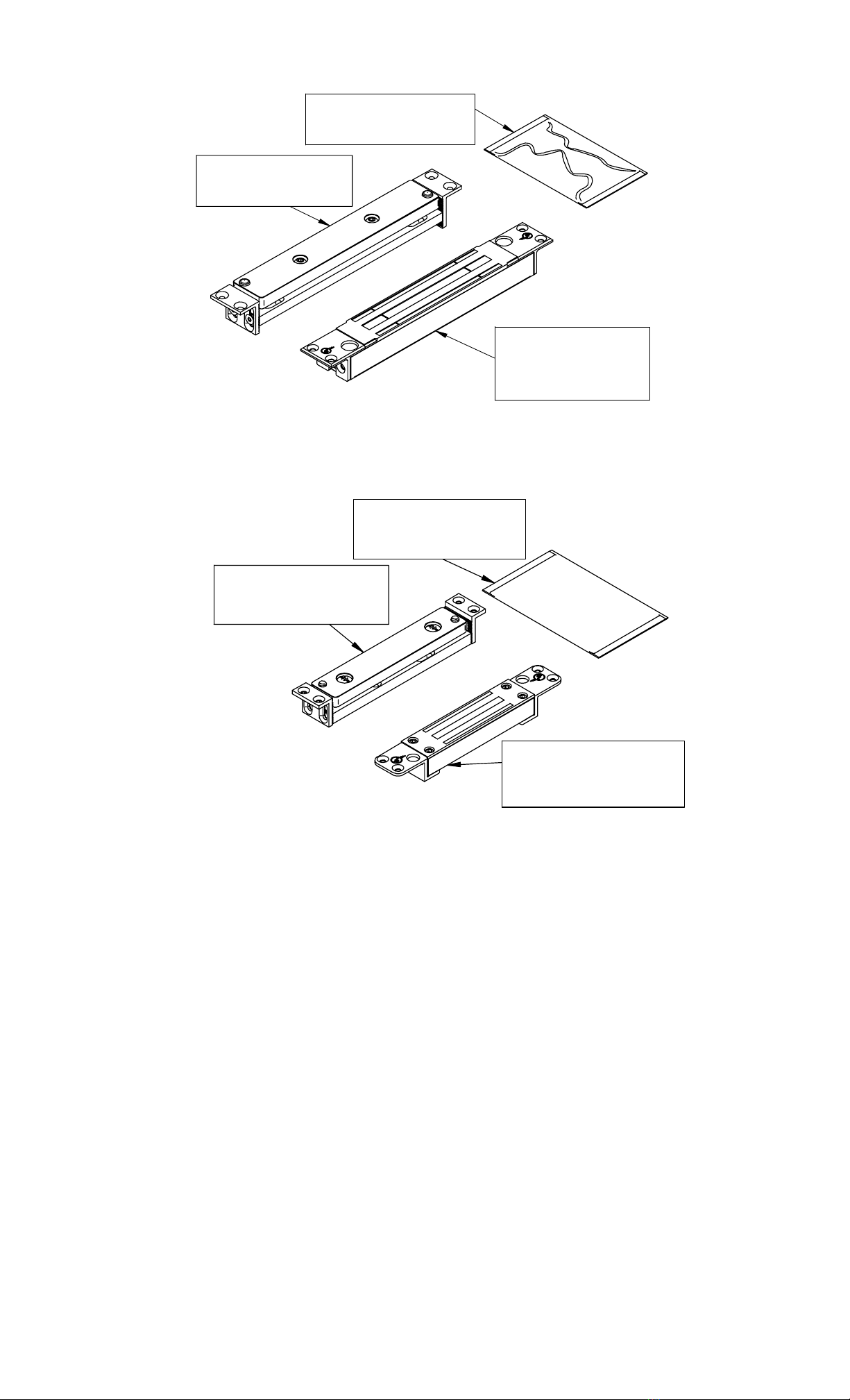
3. PRODUCT OVERVIEW
Upon unpacking this product, an inventory should be made to ensure that all the required
components and hardware have been included. Along with these instructions and the Installation
Templates this product should include the following items:
PN# 500-10440
Page 2 Rev. C, 6/07
Strike Assembly
Hardware Pack
SAM/SAMSC
Magnet Body
SAM/SAMSC Magnalock Assembly
Strike Assembly
Hardware Pack
SAM2
Magnet Body
SAM2 Magnalock Assembly
4. RECOMMENDED TOOLS
Router or Sabre Saw
Chisel
Drill Motor
Drill Bits: 7/64” [2.8mm], 9/64” [3.6mm], 3/16” [4.8mm], 5/16” [8.0mm]
Counter Sink Tool: 3/8” Diameter x 82º
Phillips and Standard Screw Driver
Measuring Tool (ruler or tape measure)
Wire Stripper
Crimping Tool
Digital or Analog Ohm Meter (for diagnostics)
1/8” Hex (Allen) Wrench ~ Included
PN# 500-10440
Page 3 Rev. C, 6/07
5. INSTALLATION INSTRUCTIONS
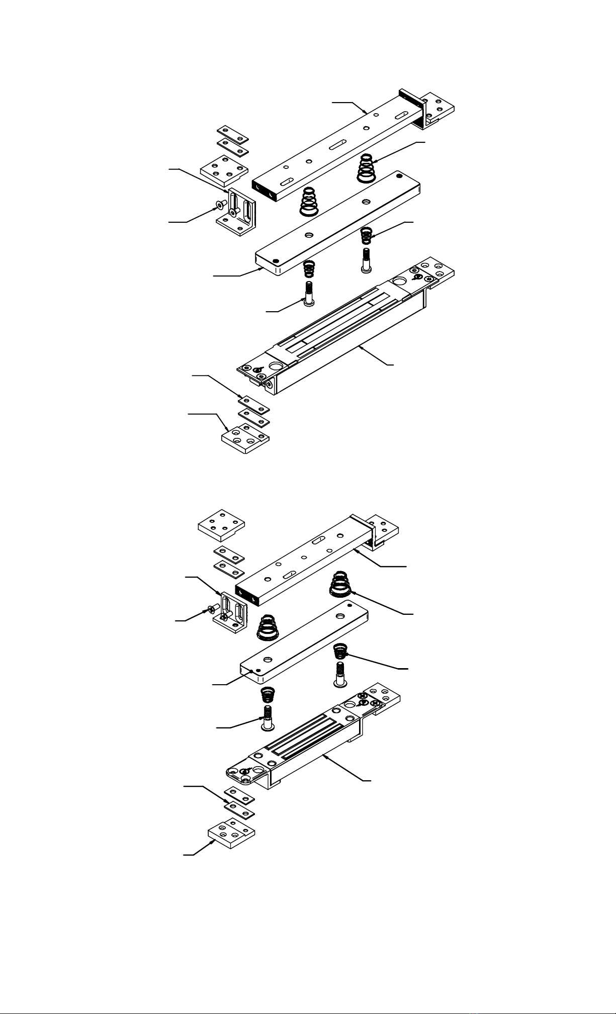
PN# 390-15910
Idle End Bracket (2)
PN# 300-12165
10-32 x 1/2" Screw (20)
Metric PN# 300-12170
M5 - 0.8 x 10mm Screw (20)
PN# 390-11420
1/16" Shim Plate (8)
PN# 390-15900
Flush Mount Bracket (4)
Metric PN# 390-15950
PN# 300-12408
Strike Shoulder Screw (2)
PN# 775-40200
SAM Strike Plate
Magnet Body
PN# 390-15920
Idle Bracket (1)
Idle Plate Compression Spring
PN# 560-13025 (Standard Mount) (2)
PN# 560-13045 (Floor Mount) (2)
PN# 560-13035
Strike Plate Compression Spring (2)
Figure 1
Shear Aligning Magnalock Assembly (SAM/SAMSC)
PN# 390-15970
Idle End Bracket (2)
PN# 300-11630
8-32 x 1/2" Screw (20)
Metric PN# 300-11635
M4 - 0.7 x 12mm Screw (20)
PN# 390-11460
1/16" Shim Plate (8)
PN# 390-15960
Flush Mount Bracket (4)
Metric PN# 390-16400
Magnet Body (1)
PN# 390-15980
Idle Bracket (1)
Idle Plate Compression Spring
PN# 560-13080 (Standard Mount) (2)
PN# 560-13085 (Floor Mount) (2)
PN# 300-12408
Strike Shoulder Screw (2)
PN# 560-13090
Strike Plate Compression Spring (2)
PN# 380-20010
SAM2 Strike Plate (1)
Figure 2
Shear Aligning Magnalock Assembly (SAM2)

PN# 500-10440
Page 4 Rev. C, 6/07
5.1 SurveyLocation of the lock mounting should be decided before proceeding with the
installation. The door and frame areas need to be examined for mortising capabilities, sufficient
size and without any internal obstructions. The top-of-door installation is the most suitable
location for protection from impact attacks.
5.2 Frame and Door Preparation
5.2.1 Frame Preparation
Locate and mark the center-line position of the strike assembly on the door. Using the door
marks as reference, mark the center locations of the lock onto the door frame. Using the lock
template provided, center the template location onto frame and mark the mortise cut-out area.
Route the area for the lock mounting. Insert the lock into the frame and mark the bracket
locations for the mounting holes. Following the drill size instructions on the template and drill the
proper hole locations for mounting. Offset the lock from the corner of the frame approximately
2”. There is not a recommended distance, but the distance should be as close to the frame
corner as possible to maintain the integrity of the locks holding force. Also check the strike
mounting area for obstacles when planning the locks location. Make certain that the strike
mounting area does not have any obstructions that might hinder the installation.
5.2.2 Door Preparation
Centering the position of the magnet body is more critical because there is not a lot of free width
in the door frame and door to accommodate any centering error when the SAM is mounted. To
set your centerline in the door frame, make sure the door is closed properly (against the stop in
the case of a single acting door or in centered rest position in the case of a double acting door).
Note that the door closer may need adjustment particularly in the case of a double acting door.
Then, using a pencil, trace the edges of the door on the frame indicating precisely how the door
lines up under or adjacent to the frame. Measure the distance between the two “door lines” and
set your magnet body mounting center line in the middle of these two lines. Next, you are ready
to identify the correct template and prepare the frame to receive the magnet body.
Locate the position of the center-line mark for the strike assembly on the door. Close the door
and measure the distance from the edge of frame to the face of the door. Open the door and
measure the distance from the door stop to the center of the lock location. Take the sum of the
center of door location (7/8”) and the stop to door face (1/8”) (exp: (7/8” + 1/8” = 1). Mark the
distance on the frame to the center of the lock measuring from the door stop which equals 1”.
Note: If the bottom mounting is chosen, the two (2) Idle Plate Springs (PN# 560-13025) in the
Strike Assembly need to be replaced with the extra set of (2) Idle Springs (PN#560-13045)
provided in the hardware pack.
5.3 Mounting Magnet Body
The cable exit location needs to be determined when installing the magnet body. The lock is
symmetrical which allows the cable exit from either end into the door frame. There are different
techniques for mounting lock depending on the type of stile of doors and frames. The next three
sections entail installation conditions using hollow aluminum, steel and wood type doors and
frames. The following Figure 1 and Figure 2 illustrations display exploded views of the SAM and
SAM2 assembly parts. These parts will be referenced during the following Magnet Body and
Strike Assembly installation procedures. Use the diagrams to understand the names of these
parts.
5.3.1 Hollow Aluminum and Metal Door Frames
Using the template provided reference the center locations previously determine during the
survey of the door/frame preparation. Mark the area of the door frame to be mortised for the
magnet location. By using the router or sabre saw, cut out (mortise) the desired area. Be aware
of the center location of the lock in accordance with the center of the door strike location.
Note: When determining the position the magnet and strike, be sure that the strike will go into
the adjacent area of the door without encountering any obstacles that may interfere with
mounting, such as a door adjustment screws or door closer apparatuses.
Place the lock body into the cutout area to ensure proper fit. Perform any filing or cutting
necessary to finish the mortised area for proper fit. Properly mark and drill all necessary holes

PN# 500-10440
Page 5 Rev. C, 6/07
needed to mount the magnet body and flush mount brackets into place as indicated on the
templates provided. The flush mount brackets are shown installed in Figure 3 and Figure 4
below. The variation in the frame thicknesses is adjustable by reversing or flipping the flush
mount brackets.
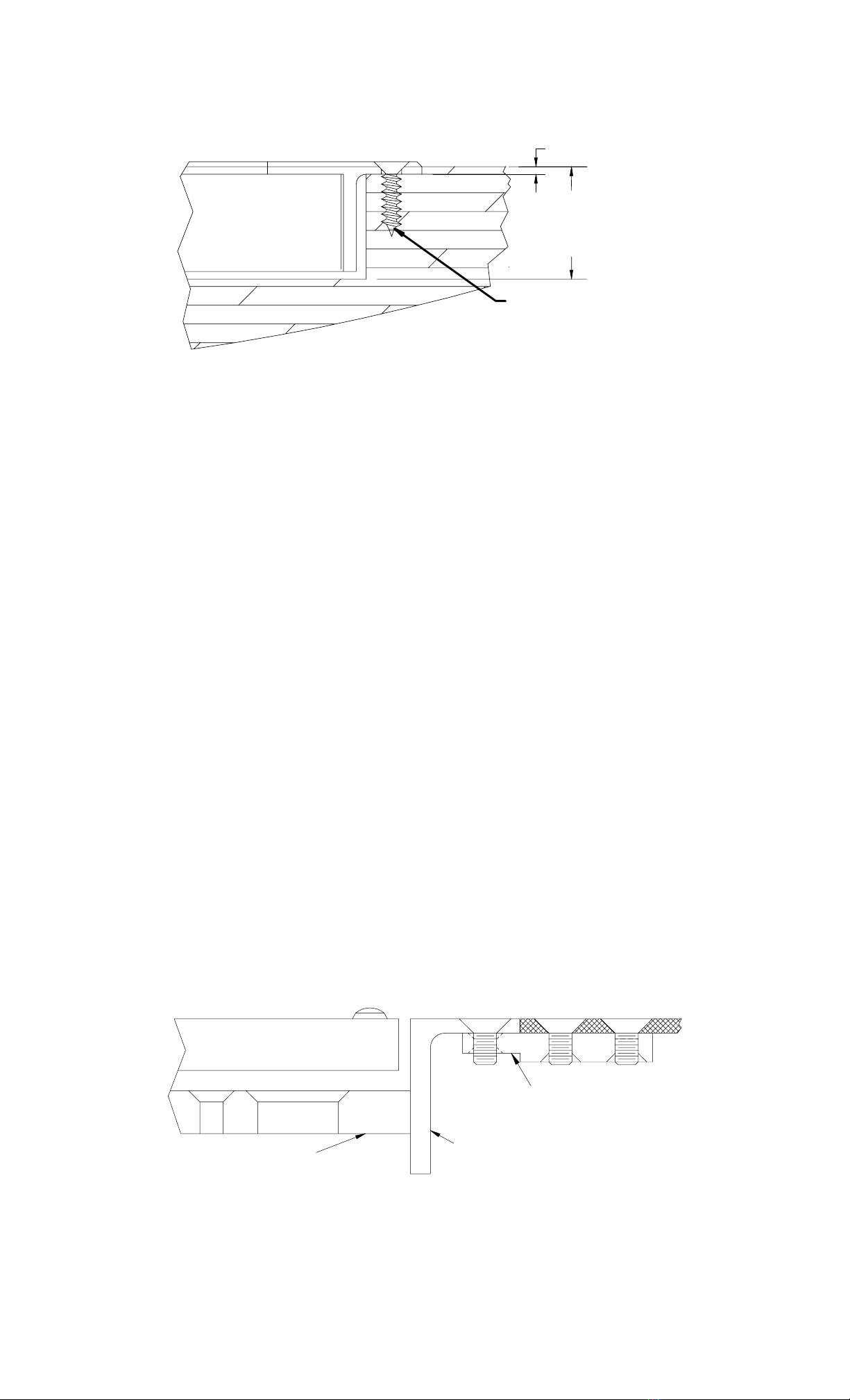
Flush Mount Bracket
(Note Orientation)
- - - - - - - - - - - - - - - -
Apply Threadlock
To Screw Threads
Figure 3
Flush Mount Bracket Mounting (Thin Wall Frame)
The flush mount brackets also come with shim plates allowing other variations in the exposed
height of the lock and/or the variation in thickness of door frames. It is recommended that the
magnet face protrude approximately 1/16” [1.5mm] beyond the surface of the frame. Figure 3
and Figure 4 have shim plates in place to raise the magnet above the frame surface.
Note: Apply the Threadlock provided to all mounting machine screw threads.
Flush Mount Bracket
(Note Orientation)
- - - - - - - - - - - - - - - -
Apply Threadlock
To Screw Threads
Figure 4
Flush Mount Bracket Mounting (Thick Wall Frame)
5.3.2 Solid Wood Door Frames
Using the template provided, reference the center locations previously determined during the
survey of the door/frame preparation. Mark the area of the door frame to be mortised for the
magnet location. Using a router or chisel, cut out (mortise) the desired area. Be aware of the
center location of the lock in accordance with the center of the door strike location. The depth of
the mortise cut out is important depending on the lock model being installed. The minimum
depth of the cut out is noted in Figure 5 below.
Note: When determining the position of the magnet and strike, be sure that the strike will go
into the adjacent area of the door without encountering any obstacles that may interfere with
the mounting, such as a door adjustment screws or door closer apparatuses.
Place the lock body into the cut-out area to ensure proper fit. Perform any filing or cutting
necessary to finish the mortised area for proper fit. Properly mark and drill all necessary holes
need to mount the magnet body into place as indicated on the templates provided. The step
shown in Figure 5 indicates the required recessed depth of 1/16” [1.5mm] for the mounting
brackets. The actual height is to be determined by the installer. If the step applied is to deep,
PN# 500-10440
Page 6 Rev. C, 6/07
use the shim plates provided to raise the lock to the proper finished height. The clearances
behind the lock, shown In Figure 5, are only minimum depths. Mount the Magnalock into place
with the wood screws provided.
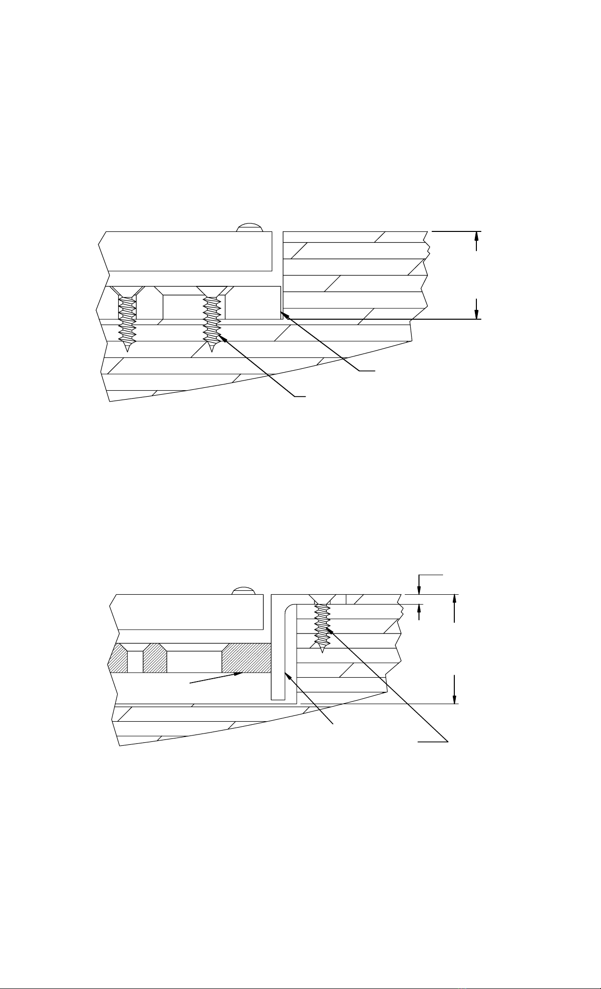
Mortise Depth
SAM: 1-1/8"
SAM2: 1"
1/16"
Flathead Sheet Metal Screw
#10 x 3/4" (SAM)
#8 x 3/4" (SAM2)
Figure 5
Wood Frame Lock Bracket Mounting
5.4 Mounting the Strike Assembly
The strike plate mounting technique varies with the type of door used in the installation. The
types of doors are illustrated on the two (2) templates provided. The following sections describe
the door type and installation procedures. The design of the strike bracket assembly has
adjustment features. These features are designed in to help properly install and adjust the strike
assembly for proper operation. Before mounting the strike, examine the strike assembly and its
unique features. The End Brackets are serrated to adjust the height of the unit in the door edge.
Both ends are identical and the Idle Bracket has matching serrations. The sides of the brackets
have oblong holes to limit the adjustment travel and to support the structure of the assembly.
By loosening the bracket screws, the bracket can be adjusted to the desired mounting height.
The notches on the brackets are .050” [1.3mm] apart. The notch distance matches the screw
thread count distance that mounts the strike which will be explained during the final adjustment
in Section 5.5. The brackets can be reversed for deeper mounting configurations. See Figure 6
and Figure 7 for adjustable ranges and mounting methods.
Note: The position of the center-line of the strike assembly is critical to the lock location.
5.4.1 Hollow Aluminum and Metal Door Frames (Flush Top)
Mounting the strike assembly onto doors with flush outside surfaces have some of the same
methods as mounting the lock into the same hollow metal type frame. The strike mounting area
is cut out using a router or sabre saw. The templates provided specify the dimensions of the cut-
outs and the locations of the holes for proper mounting. In this process the Flush Mount
Brackets are used to suspend the strike assembly into the door. Make the necessary
adjustments of the End Brackets to set the initial strike height in the door installation. The Flush
Mount Brackets may be installed either direction to set the flush mount conditions of the
installation. Also shim plates are available to assist any further needs for adjustment in the
installation. See Figure 6 below on a typical installation in a flush type aluminum door. Also
reference the previous Figures 3 and 4 on the Flush Mount Bracket reversibility.
Note: Apply the Threadlock provided to all mounting machine screw threads.
Flush Mount Bracket
(Note Orientation)
- - - - - - - - - - - - - - - -
Apply Threadlock
To Screw Threads
End
Bracket
Idle
Bracket
Strike
Figure 6
Hollow Frame Strike Bracket Mounting
5.4.2 Hollow Aluminum Door (Shallow Recess Top)

PN# 500-10440
Page 7 Rev. C, 6/07
There are several methods for mounting the strike assembly onto doors with recessed surfaces.
The door recess depth determines if cutting or routing will be necessary to provide enough room
for the strike assembly to mount. Reviewing the illustrations in Figure 7 and Figure 8, the door
range depths are clarified. If the door ranges are within the shallow specifications noted in
Figure 7, a cut out area will be needed to insert the strike assembly. Cut out the strike mounting
area using a router or sabre saw. The templates provided specify the dimensions of the cut-outs
and the locations of the holes for proper mounting. In this process the Flush Mount Brackets are
not used. The strike can mount suspended in the door using the door edge only. Make the
necessary adjustments of the End Brackets to set the initial strike height in the door installation.
If necessary, use the provided Shim Plates under the bracket mounts when the adjustment
ranges aren’t suitable.
.125 - 1.375 (SAM)
.125 - .875 (SAM2)
Cross Section
of
Door Recess
#8 x 3/4"
Flathead Sheet
Metal Screw
End
Bracket
Idle
Bracket
Strike
Figure 7
Shallow Recess Door Strike Mounting
5.4.3 Hollow Aluminum Door (Deep Recess Top)
The mounting the strike assembly onto doors with deep recessed surfaces, turn or flip the End
Brackets around to increase the height range of the Strike Bracket Assembly. Reviewing Figure
8, the depth of the door ranges is specified. In this process the Flush Mount Brackets are not
used. The strike will mount staged from the bottom of the door recess by using the frame only.
Make the necessary adjustments of the End Brackets to set the initial strike height in the door
installation. Use shim plates if necessary where the End Bracket adjustments aren’t suitable for
the range chosen.
Note: Apply the Threadlock provided to all mounting machine screw threads.
1.500 - 2.000 (SAM)
1.000 - 1.500 (SAM2)
Cross Section
of
Door Recess
End
Bracket
10-32 x 3/8" (SAM)
8-32 x 1/2" (SAM2)
Flatehead Screw
Into Tapped Hole
Idle
Bracket
Strike
Apply Threadlock
To Screw Threads
Figure 8
Deep Recess Door Strike Mounting
PN# 500-10440
Page 8 Rev. C, 6/07
5.4.4 Hard Core Wood Door
There are several methods for mounting the strike assembly onto hard core wood doors.
Depending on the door stile, the strike assembly may be mounted with or without the End
Brackets attached. The door cut-out requires a mortise area for the strike base assembly with
optional sizes depending if the use of End Bracket is desired. The depth requirements are
illustrated below in Figures 9 and 10. If the installation does not require End Brackets, as shown
in Figure 9, the installer must be accurate on the depth of the cut-out. If mortised too shallow,
adjusting the strike down lower will not be capable and the door operation may be hindered. If
the cut-out is too deep, shimming will be necessary to adjust to Idle Bracket height in the
installation. If the installation does require the End Brackets, the cutout area is set to a
minimum depth. Over cutting the depth will not affect the installation. Using the End Brackets
makes it able to adjust the initial installation height of the strike assembly.
Mortise Depth
SAM: 1"
SAM2: 7/8"
Flathead Sheet Metal Screw
#10 x 3/4" (SAM)
#8 x 3/4" (SAM2)
Idle Bracket
Strike
Figure 9
Wood Door Strike Mounting without Brackets
5.4.5 Soft Core Wood Door
It is recommended to use the End Bracket when installing the Strike Assembly on soft core wood
stile doors. The soft core doors are not of adequate strength and the End Brackets will help the
structure to the installation. Refer to Section 5.4.1 for use of the End Brackets. Figure 10
illustrates the dimensional features and aspects of the installation into soft core wood doors.
Mortise Depth
SAM: 1-7/16"
SAM2: 1"
1/8"
Strike
Idle Bracket
End Bracket
Flathead Sheet Metal Screw
#10 x 3/4" (SAM)
#8 x 3/4" (SAM2)
Figure 10
Wood Door Strike Mounting with Brackets
PN# 500-10440
Page 9 Rev. C, 6/07
5.5 Strike Assembly Final Adjustments
5.5.1 Strike Level Adjustment (De-energized)
De-energized adjustment of the strike height is important for proper door/lock operations. The
example in Figure 11 below illustrates the lock with the proper adjustment. Without power
applied to the lock, both of the Interference Buttons should just clear the lock brackets. Check
this by opening and closing the door. To adjust the clearance to be closer, turn the adjustment
screws, in the center of the strike counter-clockwise ¼ turn, one at a time and recheck the
clearances. Both screws do not have to be adjusted the same amount of turns. The adjustments
should be made independently so that the strike level is uniform to the door frame and lock
installation. The strike screws are allowed up to two (2) full turns of adjustment each. If the
adjustment is two (2) turns or greater, turn the screws clockwise back to the down position and
adjust the end brackets the amount of notches necessary to start the final adjustments and
repeat adjustments again until satisfied with the height set.
Note: The Interference Buttons on the Strike should just clear the magnet Body Surface to
insure the correct gap.
Magnet Body
Strike
1/8" Approximate
Clearance
Lock
Bracket Interference
Button
Figure 11
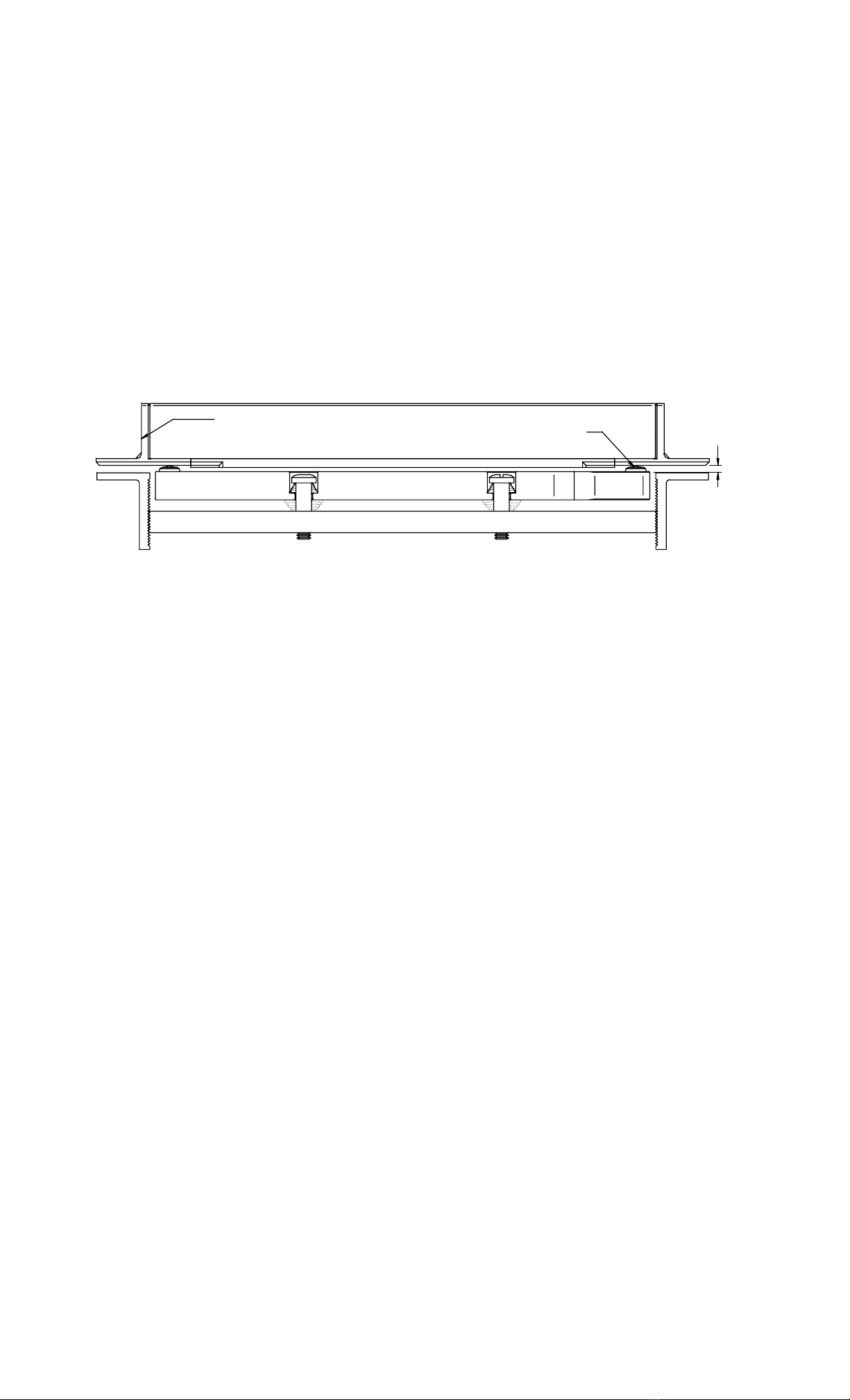
Magnet Body and Strike Assembly (Side View)
5.5.2 Strike Adjustment Testing (Energized)
Energized adjustment testing of the strike height is important for proper door/lock operations.
This adjustment should be performed after the de-energized adjustment, illustrated in Section
5.5.1. With the door closed and the lock de-energized, energize the lock. The strike should pull
up against the lock face. De-energize and the strike should return to the previously adjusted
height. It is good to test this several times to insure that the strike level adjustment is correct. If
the strike does not pull up to the face of the lock, the strike is to low. Making small ¼ turn
adjustments should be performed until the correct level and clearances are correct.
A second test should be performed with the door opened. Energize the lock and close the door
under normal operations. The strike should be attracted to the magnet body, but the strike
should pass completely into the locking position and secure the door. Test this operation several
times to ensure the operation of the strike and also the alignment of the lock/strike installation.
Note: When the lock is energized for a continuous duty mode, the adjustments made make it a
positive locking mode for controlled access. If the lock is set for continuous duty, the exit
request allows the strike to drop away and clear for smooth egress. When the lock becomes
energized, while the door is still in the opened position, the door closing and locking features will
still function, When the door closes, the strike will walk back to the locking position and secure.
There should be no interferences that may cause the door not to close and become secure.
5.6 Mounting On Motorized Bi-Parting Doors
Bi-Parting Motorized Doors are commonly found on the perimeters of large retail stores such as
supermarkets. One (1) or two (2) doors electrically slide open for entering or exiting purposes.
They are typically activated by either a motion detector or pressure sensitive type mat. The
doors are also designed to allow emergency egress in the event of a fire. The emergency egress
is allowed by a fail safe condition to the door. This is used to turn off any lock peripherals or
motor devices that operate or secure the door. The door is designed with a secondary directional
movement to swing open is called “breakaway”.
Doors that are set to remain locked, after the establishment has closed, have the possibly of
accessing the breakaway feature by prying the door open. Installing a SAM Magnalock in the
door for access control will help resist the possibility to enter through the breakaway feature.
PN# 500-10440
Page 10 Rev. C, 6/07
6. OPERATIONAL INSTRUCTIONS
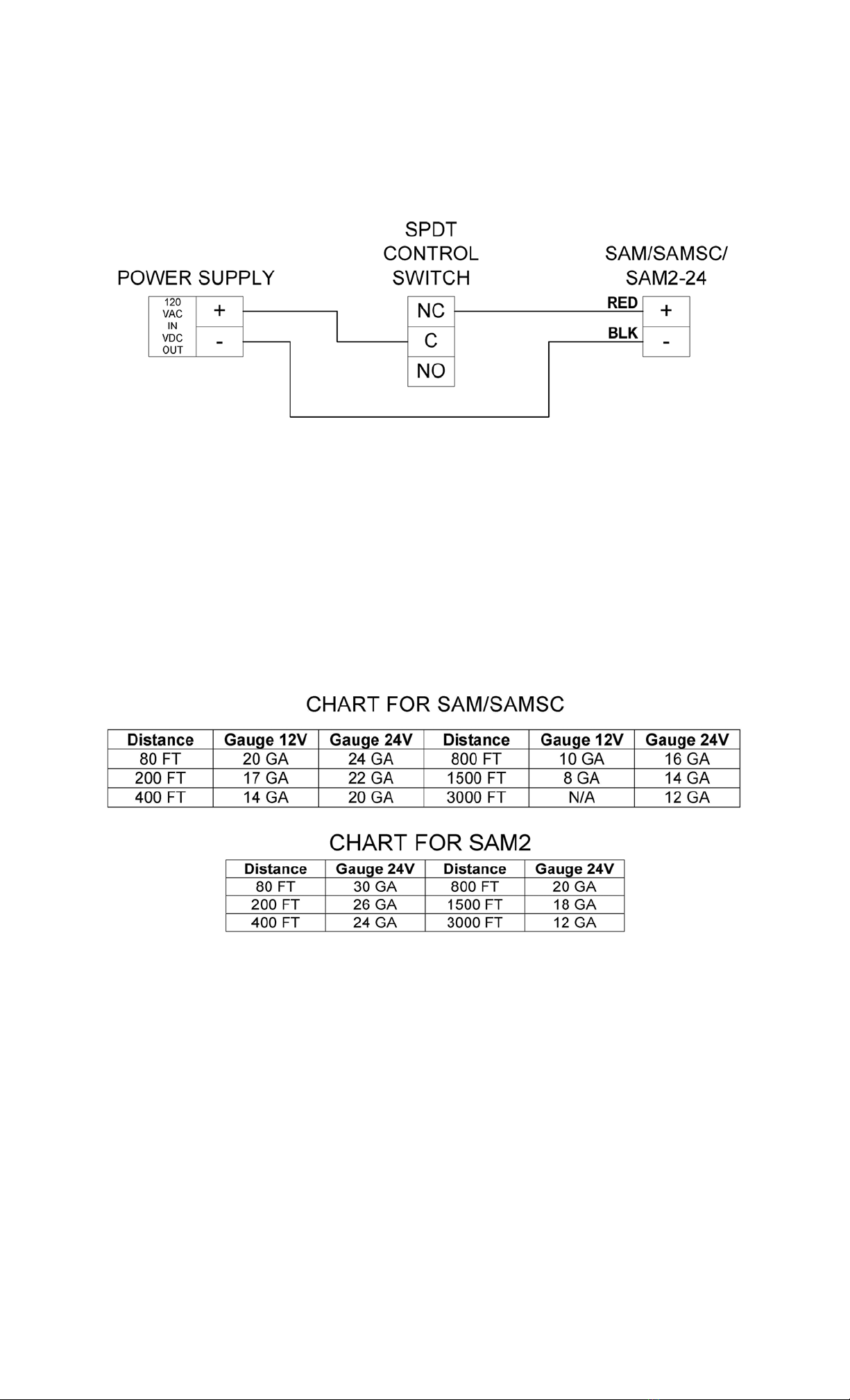
The Securitron Model SAM/SAMSC and SAM2 Magnalocks are Fail Safe locking devices (power to
lock). To power the Magnalock simply apply positive DC voltage to the red wire through a
normally closed switch. The black wire is applied to the negative DC voltage. The Figure 12
wiring diagram below provides an example of the proper connection.
Figure 12
6.1 WIRE GAUGE SIZING
If the power supply is distant from the lock, voltage will be lost (dropped) in the connecting
wires so that the Magnalock will not receive full voltage. The following chart shows the minimum
wire gauge that will hold voltage drop to an acceptable 5% for different lock to power supply
distances. Proper use of the chart assumes a dedicated pair of wires to power each Magnalock
(no common negative). Note that a Magnalock operating on 24 volts is a much better choice for
long wire runs as it has 4 times the resistance of a 12 volt installation. Also note that the correct
calculation of wire sizing is a very important issue as the installer is responsible to insure that
adequate voltage is supplied to any load. In multiple device installations, the calculation can
become quite complex so refer to Section 9 Appendix A for a more complete discussion.
6.2 “SC” SENSTAT WIRING (OPTIONAL)
The Securitron's optional patented Senstat feature provides true lock status sensing and is
available on the Model SAMSC. In many electrically controlled door security systems, status
sensing is provided by a magnetic switch on the door itself. This indicates the door is closed but
not necessarily secured. Securitron's Senstat monitors the lock rather than the door and
therefore provides higher security (but note that it can’t be used as an auto-relock input to an
access control system).
The SAMSC provides a dry SPDT output which changes state when the lock is reporting secure (1
Amp @ 30 VDC maximum). This is accomplished by conducting the input power of the lock
through the strike and employing it to energize an internal SPDT relay. The white wire is the
Senstat relay common. GREEN is closed to WHITE when the lock is secure and ORANGE is closed
to WHITE when the lock is not secure. The Figure 13 wiring diagram provides an example of the
proper connection.

PN# 500-10440
Page 11 Rev. C, 6/07
Figure 13
6.3 “SC” SENSTAT DOUBLE DOOR WIRING
Some installations contain two (2) SAM Magnalocks mounted in a double door configuration and
both are turned on and off concurrently (no separate control). As to status reporting, it is of
course possible to receive a separate Senstat status signal from each door or you can combine
the outputs so that if both locks are secure, the double door is secure and if either lock is not
secure, the double door is not secure.
Simply series the WHITE and GREEN wire together from the two locks. A circuit will be closed
between the other WHITE and GREEN wires when both locks are reporting secure. If either is not
secure, the circuit between the WHITE and GREEN wires will be open. The ORANGE wires are not
used. The Figure 14 wiring diagram below provides an example of the proper connection.
Figure 14
7. MAINTENANCE
Maintenance for SAM/SAMSC and SAM2 Magnalock is very simple. Once every six months we
recommend taking a clean cloth and rubbing alcohol or a non-abrasive cleaner and wiping down
the face of the Magnalock, the Mounting Bracket detents and the Strike Armature Assembly. This
prevents a build up of foreign materials from the air making the Magnalock stick.

PN# 500-10440
Page 12 Rev. C, 6/07
8. TROUBLESHOOTING
PROBLEM-- No magnetic attraction between magnet and strike plate
To verify no magnetic attraction, attempt to put a steel object like a paperclip or screwdriver
against the magnet surface (covering at least two bars of the magnet body). It should adhere
weakly. If it falls away with no adherence, you have no magnetic field. To analyze the problem,
first be sure the lock is being correctly powered with DC voltage. This includes connecting the
power wires with correct polarity. Positive must go to red and negative to black. If the SAM is
wired in reverse polarity, it will not be damaged, but it will not operate. If the unit continues to
appear dead, it must be electrically checked with an Ammeter. It must be powered with the
correct input voltage and checked to see if it draws the specified current. If the unit meters
correctly, it is putting out the correct magnetic field and the problem must lie with the mounting
alignment in the door (see next paragraph).
PROBLEM-- The lock does not engage even though magnetic attraction is present
The SAM operate by pulling the strike plate against the magnet face when the door closes
thereby seating interference buttons on the strike into corresponding machined holes at either
end of the magnet body. If the buttons do not seat, the lock will not hold and should be
considered not engaged. There are three potential causes that can produce a failure of the
buttons to seat. First the mounting alignment between the strike and the magnet body can be
off such that the buttons don’t line up with the conical machined holes in the T brackets. To
make this unlikely, the diameter of the machined holes exceeds that of the buttons by 1/8” and
this provides a margin for error in mounting. A misalignment greater than this either along the
long axis of the lock or in the door closing direction will cause engagement failure. You can
normally visually detect such an alignment problem. Watch the strike closely as you very slowly
close the door. You should see it “try” to move against the magnet body but note that the
buttons are acting as stand-offs because they are not lining up with the holes. In some cases,
this problem can be corrected by adjusting the door but re-mounting the unit properly is often
required.
The second possible cause is that the gap between the magnet body and strike plate has
widened to the point that the magnet can no longer pull the strike plate in. This can happen, for
example, when the lock is mounted at the top of the door and the door sags downwards which
increases the gap. Note that the gap is supposed to be 1/10” or the point at which the tops of
the buttons just graze the magnet surface. If the actual gap is significantly greater than this,
you have found the problem. It can be corrected by either readjusting the hanging position of
the door or readjusting the level of the strike (by turning the two strike mounting screws) so as
to reduce the gap to the correct dimension. The final possible cause is that the strike mounting
hardware has somehow become frozen so that the strike has lost its movement ability towards
and away from the magnet body. You can check this by trying the move the strike by hand with
the door open. If it does not move, dismount the strike assembly and clean, lubricate or replace
the mounting hardware.
PROBLEM-- Reduced holding force
This problem usually expresses itself in terms of being able to kick the door open or to open it
with a shoulder. The cause is usually a build-up of dirt or other material between the magnet
body and strike. Check to see if anything is interfering with a flat fit. Even a small air gap can
greatly reduce the holding force. Another possibility is if you are operating the lock on AC
instead of DC or on half wave rectified DC (transformer + single diode). Half wave rectified DC is
unacceptable; you must, at a minimum employ full wave rectified DC (transformer + bridge).
PROBLEM-- The Senstat output does not report secure
Because of the simplicity of Securitron's patented Senstat design, this is almost always a case of
the lock status sensor doing its job. It is not reporting secure because a small obstruction or too
stiffly mounted strike is causing the Magnalock to hold at reduced force. The problem is
corrected by cleaning the surfaces of the magnet. If this doesn't work, you can verify function of
the Senstat feature as follows. Note that there are 2 thin vertical lines on the magnet face that
can be said to separate the core into 3 sections from left to right. The Senstat output is created
by the strike establishing electrical contact between the leftmost and rightmost core segments.
With the lock powered, use a pair of scissors and press the points respectively into the leftmost
and rightmost core segments. The Senstat output should then report secure. This shows that the
problem lies in the strike not making correct flat contact with the magnet face. If the scissors

PN# 500-10440
Page 13 Rev. C, 6/07
technique doesn't cause the lock to report secure, check to see if there is a broken Senstat wire.
If this is not the case, the lock must be returned to the factory for replacement.
PROBLEM-- The lock does not release
When power is removed, the SAM releases as magnetic attraction is gone and the angles on the
edges of the interference button “ramp” the strike off the magnet face. If the unit fails to
release, the first possible cause to consider is that power may not have been successfully
removed. This is generally a wiring integrity problem. What happens is that an upstream switch
removes power from the wires going to the Magnalock, but through an installation error, the
wires have their insulation abraded between the switch and lock so that partial or full power can
leak in from another Magnalock or other DC device with similarly abraded wiring. This is most
likely to occur at the point where the wire cable leaves the lock case and enters the door frame.
Another area is via an improper splice on wiring in conduit. Either a metal door frame or the
metal conduit is capable of leaking power between multiple devices with abraded wires, thereby
bypassing switches. A good way to check this electrically (as opposed to visually removing and
inspecting the wires) is to use a meter and check for leakage between the power supply positive
or negative and the door frame and conduit. Magnalocks should be powered by isolated DC
voltage without any earth ground reference to positive or negative. A second possible cause is
mechanical bonding via vandalism. By mechanical bonding, we simply mean that glue has been
applied between the strike and magnet as a prank. Finally, the SAM will not release if the strike
plate is not able to pull away from the magnet body when power is cut. The strike may somehow
have become wedged against the edge of the door. This is easily detectable by manually
attempting to move the strike towards and away from the magnet body.
PROBLEM-- Apparent electronic noise interference with the access control system
Electric locks, being inductive devices, return voltage spikes on their power wires and also emit
microwave radiation when switched. This can interfere with access control electronics causing
malfunctions. Access control contractors often employ installation techniques designed to isolate
the access control electronics from the electric lock. These include separate circuits for the lock,
shielded wiring and other techniques. These techniques will vary with the sensitivity of the
access control system electronics and should, of course, be followed. Note that the SAM includes
internal electronics which suppress both inductive kickback and radiation. They have been
extensively tested and accepted by numerous access control manufacturers and have been used
in thousands of installations without incident. An apparent noise problem is therefore usually not
caused by the Magnalock. The access control equipment may be itself faulty or have been
installed improperly.
IF A PROBLEM PERSISTS CALL SECURITRON TOLL FREE AT (800) MAGLOCK

PN# 500-10440
Page 14 Rev. C, 6/07
9. APPENDICES
9.1 Calculating Wire Sizes
The general practice of wire sizing in a DC circuit is to avoid causing voltage drops in connecting
wires which reduce the voltage available to operate the device. As the SAM is a low power
device, it can be operated a long distance from its power source. Long wire runs, must be able
to calculate by the installer to determine the correct gauge of wire to avoid excessive voltage
drops by adding the resistance of the Magnalock and resistance in the power wires followed by
dividing the wire resistance by the total resistance. This yields the fraction of voltage drop in the
wires. For example: A SAM operating on 24 volts has a resistance of 140 ohms. If the wires
completing the circuit between the Magnalock and its power source have a resistance of 10
ohms, the total resistance is 150 Ohms. Dividing 10 Ohms (the wire resistance) by 150 (the
total resistance) yields roughly 1/15 or 6.7% voltage dropped in the wires. With an input voltage
of 24 volts, 6.7% (1.6 volts) leaves 22.2 volts to the Magnalock. There will be a small reduction
in holding force but in general, but is acceptable.
To calculate the wire resistance, the distance from the power supply to the Magnalock and the
gauge (thickness) of the wire is required. The following chart shows wire resistance per 1000 ft
(305 meters):
More Examples: A SAM operating at 24 volts is1200 ft from the power supply with 20 gauge
wire. The total length of the power wires is considered 2400 ft. The resistance is 2.4 X 10.1
Ohms = 24.2 Ohms. Add the 24.4 Ohms to the SAM resistance, 140 Ohms, giving a total
resistance of 164.2 Ohms. 24.2 divided by 164.2 yields the percent drop in the wires which is
nearly 15%. There are two (2) ways can to solve the issue. Utilizing 16 gauge wire will reduce
the drop to a 6% range or provide extra voltage at the power supply (sometimes the wiring is
pre-existing). For example, a Securitron 24 V power supply is adjustable from 24 to 28 volts.
Setting the power supply at 28 volts will supply 14% over voltage and could compensate for the
15% voltage drop in the wires. If the power supply is operating a number of locks, the locks
closer the supply will receive higher voltage, but the SAM will accept up to 30% over voltage
without ill effects. If multiple locks are installed using a single power supply, the calculation of
wiring voltage drops is more difficult. The calculation has been described above, but if a common
power wire is used in a loop structure. Powered by the single loop will have an increasingly low
combined resistance and the locks don't receive proper voltage. To obtain the combined
resistance of multiple locks, divide the resistance of one lock by the total locks. Example: Eight
(8) SAM Magnalocks operating at 24 volts have a combined resistance of 140 ohms divided by 8
which is only 17.5 Ohms. Another method is to calculate the current in Amps in the wire and
divide that into the circuit voltage. Since each SAM operating at 24 volts draws .175 Amps, eight
would draw 1.4 Amps. Dividing this into the same 24 volt input voltage yields the same 17.5
Ohm combined resistance.
Patents
Securitron’s Shear Aligning Magnalock is covered under U.S. patent #4,516,114 and U.S. patent
#6,007,119 with other US and international patents pending.
Wire Gauge Resistance/1,000 ft Wire Gauge Resistance/1,000 ft
8 Gauge .6 Ohms 16 Gauge 4.1 Ohms
10 Gauge 1.0 Ohms 18 Gauge 6.4 Ohms
12 Gauge 1.6 Ohms 20 Gauge 10.1 Ohms
14 Gauge 2.5 Ohms 22 Gauge 16.0 Ohms

PN# 500-10440
Page 15 Rev. C, 6/07
MAGNACARE®LIMITED LIFETIME WARRANTY
SECURITRON MAGNALOCK CORPORATION warrants that it will replace at customer’s request,
at any time for any reason, products manufactured and branded by SECURITRON.
SECURITRON will use its best efforts to ship a replacement product by next day air freight at
no cost to the customer within 24 hours of SECURITRON’s receipt of the product from
customer. If the customer has an account with SECURITRON or a valid credit card, the
customer may order an advance replacement product, whereby SECURITRON will charge the
customer’s account for the price of the product plus next day air freight, and will credit back
to the customer the full amount of the charge, including outbound freight, upon
SECURITRON’s receipt of the original product from the customer.
SECURITRON’s sole and exclusive liability, and customer’s sole remedy, is limited to the
replacement of the SECURITRON product when delivered to SECURITRON’s facility (freight
and insurance charges prepaid by customer). The replacement, at SECURITRON’s sole
option, may be the identical item or a newer unit which serves as a functional replacement.
In the event that the product type has become obsolete in SECURITRON’s product line, this
MAGNACARE warranty will not apply. This MAGNACARE warranty also does not apply to
custom, built to order, or non-catalog items, items made by others (such as batteries),
returns for payment, distributor stock reductions, returns seeking replacement with anything
other than the identical product, or products installed outside of the United States or Canada.
This MAGNACARE warranty also does not apply to removal or installation costs.
SECURITRON will not be liable to the purchaser, the customer or anyone else for incidental
or consequential damages arising from any defect in, or malfunction of, its products.
SECURITRON does not assume any responsibility for damage or injury to person or property
due to improper care, storage, handling, abuse, misuse, or an act of God.
EXCEPT AS STATED ABOVE, SECURITRON MAKES NO WARRANTIES, EITHER EXPRESS OR
IMPLIED, AS TO ANY MATTER WHATSOEVER, INCLUDING WITHOUT LIMITATION THE
CONDITION OF ITS PRODUCTS, THEIR MERCHANTABILITY OR FITNESS FOR ANY
PARTICULAR PURPOSE.
This manual suits for next models
1


